Introduction
The past twenty years have seen increasingly rapid advances in substrate integration technology [Reference Wu, Bozzi and Fonseca1], and the substrate integrated waveguide (SIW) has been extensively used for wireless communication systems. The SIW can seamlessly integrate with other transmission lines because of its unique structure. This technique not only has the characteristics of high Q factor and low insertion loss like the metal waveguide but also has the advantages of a compact profile, low cost, and easy fabrication of microstrip lines [Reference Chen, Hong, Hao, Li and Wu2]. Microwave and Millimeter-wave devices based on the SIW techniques are emerging in an endless stream, and a large number of papers on passive devices such as couplers, filters, power dividers, and antennas, as well as active devices such as power amplifiers [Reference Hao, Hong, Chen, Zhou and Wu3–Reference Wang and Park9]. Previous research has established that SIW structures can serve as a good solution for coupler design. In [Reference Liu, Hong, Wang, Lai and Wu10], a novel component of the half-mode substrate integrated waveguide (HMSIW) 3 dB coupler is proposed. This structure achieves a nearly 50% reduction in size without deteriorating the performance of the SIW. Reference [Reference Liu, Xiao and Mao11] proves the feasibility of H-plane multi-aperture SIW couplers. In 2020, [Reference Deng, Sun, Zhu, Han and Xue12] proposes the HMSIW directional coupler with high common-mode suppression. In [Reference Shi and Zhu13], a 20 dB SIW coupler operating at 36~42 GHz with four holes opened on the narrow wall is designed to achieve weak coupling for the 5G communication system applications. However, most studies on SIW couplers have only focused on 3 dB couplers. These coupler structures proposed in most relevant reports can't achieve excellent performance in the case of weak coupling.
So far, most of the methods mentioned in the literature to study the coupling characteristics of SIW couplers are too cumbersome, which greatly reduces the design efficiency of SIW couplers. In [Reference Liu and Xiao14], Zheng Liu adopts a simplified ray tracing method to approximate and predicts the coupling characteristics of an H-plane multi-aperture SIW coupler. The paper provides a simple and effective way to determine the geometric parameters of the multi-aperture coupler based on the SIW. In 2020, Xiyao Wang proposes an equivalent transmission line model to analyze the coupling of SIW couplers [Reference Wang, Deslandes, Feng, Chen and Che15], providing a simple and accurate method to estimate the coupling between two closely spaced SIWs sharing a row of metal cylinders simplifying the design method of SIW couplers. The conventional coupler structure based on SIW is too simple, designers lack design variables to effectively control the coupling coefficient, which has become one of the bottlenecks of SIW coupler design.
This paper presents a new broadband HMSIW coupler suitable for weak coupling mode. The main contribution and novelty of this work is the introduction of a branch-line like coupling structure. The equivalent transmission line models of the SIW coupling structures are extracted and analyzed using the even-odd mode decomposition method. This structure brings new design variables, so designers can more effectively control the coupling coefficient of the SIW structure. Furthermore, the analysis and complete design procedure are provided, where a novel weak coupling SIW coupler is proposed and fabricated. The designed coupler has the advantages of broadband, high flatness in the band, good directivity, and ease of manufacture, which can be applied to design SIW-based circuits and power sensing in the Ku-band.
The remaining part of the paper proceeds as follows. The proposed coupling characteristics analysis of SIW structures and design procedure are presented in the second part. The third part compares and analyzes the simulation and measurement results of the proposed HMSIW weak coupling coupler. Finally, a conclusion is given in the fourth part.
The analysis of design theory
The traditional SIW is integrated on the dielectric laminate, which is arranged by two lines of conducting metallic vias with the same size and spacing. This structure significantly reduces the radiation losses caused by the leakage through the gaps between vias on the dielectric. The SIW is equivalent to a conventional metallic waveguide, and different forms can only transmit a single TE or TM mode. Although the volume of the SIW is much smaller than the waveguide, the plane size is still considerable. The HMSIW is only half of SIW [Reference Liu, Hong, Wang, Lai and Wu10]. The vertical center plane along the direction of propagation is an electric field maximum when the SIW operates in the main mode, so this center plane can be considered an equivalent magnetic wall. With this virtual magnetic wall, the SIW can be divided into two parts, and each half of the SIW becomes an HMSIW structure. The cost of size reduction is that there will be an inevitable radiation loss along the open boundary [Reference Bozzi, Perregrini and Wu16]. The operating frequency of the directional coupler should be higher than the cutoff frequency of HMSIW to ensure good transmission performance of the device. In addition, the operating mode of HMSIW should be set to mode TE10. The design formula of cutoff frequency f mn and the geometric parameters of the SIW resonator are given by [Reference Iqbal, Tiang, Wong, Alibakhshikenari, Falcone and Limiti17]


where W eff and L eff denotes the effective width and length of the SIW cavity; c is the velocity of light in the free space; μ r is the relative permeability of the substrate, and $\varepsilon _{\rm r}$ is the relative permittivity of the substrate. Equation (4) indicates that the HMSIW equivalent width W H is half the SIW. The parameters of metal vias affect the radiation boundary of HMSIW. The following condition has been considered by equation (5) to eliminate radiation loss. Here, p stands for the gap between metal vias, and d is the diameter of the metal vias.
The geometrical configuration of the HMSIW forward-directional coupler is shown in Fig. 1. It consists of two HMSIW sharing a row of metal via walls, with a coupling gap in the middle for coupling. SIW-microstrip transition is necessary to facilitate the measurement of material objects and integration with other transmission lines. It is worth noting that it will bring some insertion loss. The length of the coupling gap W gap in Fig. 1 determines the coupling. Port 1 is the input port, Port 2 is used as the through port, Port 3 is the coupling port, and Port 4 is named the isolation port.
Schematic of half mode substrate integrated waveguide coupler.

Figure 2 shows the coupling and directivity of the HMSIW coupler under different coupling gap widths. It can be seen that such a structure can get good performance in the intense coupling mode, and the directivity can reach more than 12 dB. In addition, the directivity deteriorates when controlling the coupling gap W gap to implement a weak coupling mode such as 20 and 25 dB, and the flatness of the weak coupling is worse than the strong coupling. Achieving high directivity and excellent flatness in the weak coupling mode is challenging.
Comparison of coupling and directivity under different lengths of coupling gaps.

The SIW couplers with different coupling structures are proposed in [Reference Liu, Hong, Wang, Lai and Wu10–Reference Wang, Deslandes, Feng, Chen and Che15, Reference Liu and Xu18–Reference Wang, Zhou, Zhang, Wang, Lv and Zhang20]. However, the biggest problem with these coupling structures is that the design variables are single, and the coupling coefficient cannot be effectively controlled. This paper introduces several controllable design variables by adding the metal via arrays. First, we must discuss the transmission line discontinuity caused by adding metal via arrays. As shown in Fig. 3(a), a pair of metal vias perpendicular to the signal transmission direction is added to the HMSIW structure, and the length of the metal vias is W ve. Figure 3(b) shows the equivalent circuit diagram of the waveguide structure. The introduction of metal via row can be equivalent to a parallel LC resonant circuit. For HMSIM symmetrical structure, the odd mode impedance and even mode impedance of the whole coupling structure can be calculated


where Z 0e1 and Z 0o1 represent the coupling transmission line's even-mode and odd-mode impedance after adding the vertical walls, respectively. Z 0e, Z 0o, and Z 0 represent the coupling transmission line itself as the even-mode impedance, odd-mode impedance, and characteristic impedance, respectively. L 1 and C 1 are inductance and capacitance of the LC parallel circuit. It can be seen that the addition of metal vias will only introduce the imaginary part value without additional loss. To test the theory, Fig. 4 shows the S parameters of the HMSIW coupler after adding metal via walls. The insertion loss S 21 and coupling coefficient S 31 have not changed. Due to the resonance characteristics of the LC circuit, S 41 of the whole coupler has been dramatically improved at the central frequency point, but the bandwidth has been reduced. In a word, the reasonable introduction of metal via arrays will not bring more losses and can be used in the design of SIW couplers.
Schematic of (a) vertical metal walls loaded HMSIW coupling structure and (b) the equivalent circuit modal.

Simulated S-parameters of the vertical metal walls loaded HMSIW coupler.

Figure 5 depicts the HMSIW coupling topology proposed in this paper. The overall architecture is similar to the branch line coupler. It is divided into three transmission lines with different characteristic impedances and equivalent lengths, used as the feeder, direct branch, and coupling branch, respectively. This way, multiple controllable variables are introduced to control the coupling coefficient. In addition, a compensation structure based on the symmetrical parallel short stubs is added to the central hollowed area. The structure introduces the reactance value into the coupling branch. The directivity and coupling of the whole band can be optimized by changing the compensation structure's size to improve the performance of the coupler.
Schematic diagram of the weak coupling coupler with compensation structure.

The equivalent circuit model of the HMSIW weak coupling coupler is shown in Fig. 6(a). In order to deduce the detailed design process, the odd and even mode equivalent circuit is carried out for the four-port coupling network composed of the straight branch and coupling branch, as shown in Figs 6(b) and 6(c). Although mining a portion of the metal layer will result in loss G, the focus of this discussion is not on insertion loss, which can be omitted from the derivation of the formulas. B is the equivalent capacitance of the compensation structure.
(a) Topology of overall equivalent circuit, (b) odd-mode, and (c) even-mode equivalent circuit of the proposed novel weak coupling coupler.

According to the transmission line and matrix theory, the ABCD matrix A e of the two-port even-mode equivalent circuit can be expressed as

where

The S-parameter of the even-mode equivalent circuit can then be derived as


where

Similarly, the S-parameter of an odd-mode equivalent two-port circuit can be obtained


where


The characteristic impedance Z i of the HMSIW transmission lines can be expressed as

For the lossless case, R i = 0, and hence

h is the thickness of the dielectric substrate, ω c is the dielectric angular frequency of HMSIW, and ω is the central angular frequency in the designed coupler band. The electrical length θ i of the lossless HMSIW transmission line is given by

where the propagation constant γ i can be calculated as

Based on (10–14), the coupling coefficient C and isolation coefficient Is of the four-port coupling network in Fig. 6(a) can be obtained as


After determining the partial sizes of the HMSIW transmission line, the coupling degree C required by design is brought into the above formulas to calculate the remaining transmission line size of the overall coupling structure without compensation (B = 0). Next, the equivalent capacitance B is controlled by adjusting the size of the compensation structure to optimize the reflection coefficient, in-band flatness, and directivity in the entire frequency band. It is worth noting that B can be determined by changing the length of L smm. Any reactance value can be achieved when the length of L smm is within half the wavelength λ g. W s should be controlled within half of l 2 to avoid unnecessary coupling. Figure 7 shows the influence of changing the coupling branch width w 2 on the coupling degree after other dimensions of the coupling structure are determined. The coupling degree can be controlled by changing the value of w 2 to achieve the required coupling characteristics.
Effect of the parameter w 2 on the coupling degree.

Based on the above explanation, the design and optimization procedures for the size of the weak coupling coupler are summarized as follows.
1) Selecting a suitable dielectric substrate according to the frequency band required by the design to obtain the dielectric constant ɛr. The values of W H, p, and d are obtained by using the cut-off frequency f mn of the SIW structure and the general SIW rules.
2) Selecting the appropriate length l 2 of the vertical metal wall. l 2 shall not exceed half of W H.
3) Z 1 can be set freely. The equivalent width w 1 of the straight branch can be obtained by bringing the value of Z 1 into equation (18). The propagation constant γ 1 and equivalent length l 1 can be obtained by bringing w 1 into equations (19) and (20).
4) Taking the coupling degree C required by design and other calculated variables into equations (11–21), and calculating the equivalent width w 2 of coupling branch.
5) Optimizing L smm and W s in the electromagnetic simulation software, and adjusting the coupling and isolation in the entire frequency band. L smm and W s should be less than λ g/2 and l 2/2, respectively.
6) Adjusting the width w m and w t of the SIW-microstrip transition to obtain good matching performance.
The weak coupling HMSIW couplers are simulated, and shown in Fig. 8. In 14.5–19.36 GHz, the return loss S 11 exceeds 15 dB, the S 31 and S 21 are 28.3 ± 0.5 and −1 ± 0.3 dB, the directivity is greater than 12 dB, and the relative bandwidth is 28.5%. It can be concluded that both structures can realize broadband weak coupling performance and have excellent directivity and flatness.
Simulated S-parameters of the weak coupling coupler with compensation structure.

Experimental results
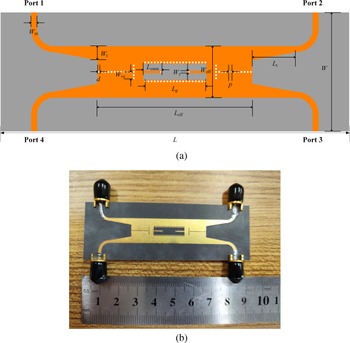
To prove the HMSIW weak-coupling design theory described in the second part, a broadband weak coupling HMSIW coupler is fabricated and tested. The PCB layout and configuration are shown in Fig. 9.
(a)The configuration and (b) PCB layout of the HMSIW coupler.

The substrate is Rogers 5880 with copper thickness and PCB thickness are 0.035 and 0.508 mm, respectively. All metal vias are identical in size. The final physical design sizes of the coupler are shown in Table 1.
Dimensions of the coupler module (unit: mm)

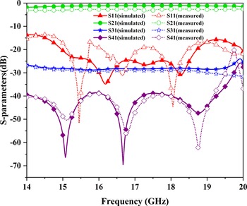
The four ports are connected with the SMA connectors, respectively. The large size of the dielectric laminate is conducive to the convenience of testing. Therefore, the coupler is fabricated on a sizeable dielectric laminate. Figure 10 shows the measured and simulated S-parameters of the coupler manufactured this time. The coupler operates in 14.5–18.75 GHz, with S 11 below −15 dB and isolation (S 41) down −39 dB. The transmission coefficient (S 21) and the coupling coefficient (S 31) are −2.5 ± 0.5 and −29 ± 0.5 dB, respectively, within 25.5% of the relative bandwidth range. The relative bandwidth of the measurement results is 3% lower than that of the simulation results. S 21 includes the line loss caused by SMA connectors and test cables, and the actual insertion loss is −1.3 ± 0.4 dB. Considering the flexibility of the dielectric substrate, manufacturing and measurement errors, the simulation results are consistent with the measured results.
Measured and simulated S-parameters of the proposed coupler.

The comparison between the proposed weak coupling coupler and other couplers is shown in Table 2. It can be seen that the coupler has better directivity, and in-band flatness than other SIW weak coupling couplers in broadband. In addition, the weak coupling coupler designed in this paper has a smaller coupling coefficient than the published weak coupling SIW coupler. The performance will decline when these couplers achieve the same coupling. Currently, some proposed SIW coupler architectures [Reference Liu, Hong, Wang, Lai and Wu10–Reference Wang, Deslandes, Feng, Chen and Che15, Reference Liu and Xu18–Reference Wang, Zhou, Zhang, Wang, Lv and Zhang20] can accomplish a weak coupling by changing parameters, but the performance will deteriorate seriously, and the directivity can hardly be used as an indicator to measure, which can also prove the superiority of the weak coupler proposed in this study.
Comparison with other referenced coupler modules

N.R, Not reported.
λ g: The operating wavelength at the center frequency.
a Relative bandwidth.
Conclusion
In this paper, a novel weak coupling broadband HMSIW coupler is proposed, simulated, and fabricated. The overall structure is similar to a branch-like coupler to achieve weak coupling characteristics. The compensation reactance is added to the parallel branches of the network to improve the bandwidth and directivity. The measurement and simulation are basically consistent. Under the operating frequency of 25.5% relative bandwidth, the coupling is 29 ± 0.5 dB, and the isolation is more significant than 39 dB. The coupler proposed in this paper complements the study of the SIW coupler in weak coupling mode. It has excellent broadband and directivity characteristics and can be applied to Ku-band power detection and power combiner circuit for satellite communication.
Acknowledgements
This work was supported by Zhejiang Provincial Public Technology Research Project (Grant LGG21F010006) and Project of Ministry of Science and Technology (Grant D20011).
Conflict of interest
None.
 Minghui You was born in Gansu Province, China, in 1998. He received the BE degree in electronic and information engineering from Chengdu University of Technology, in 2020. He is pursuing the ME degree in the School of Electronic Information, Hangzhou Dianzi University, Hangzhou, China. His current research interests include Doherty power amplifier, substrate integrated waveguide, and load modulated balanced power amplifier.
 Guohua Liu received the M.S. degree from the East China Normal University, Shanghai, China, in 2004, and the Ph.D. degree in electronic science and technology from the Hangzhou Dianzi University (HDU), Hangzhou, China, in 2020. He is currently a professor with HDU. His research interests include microwave circuits, sensors, antennas, and wireless systems design.
 Zhiqun Cheng received the B.S. and M.S. degrees from the Hefei University of Technology, Hefei, China, in 1986 and 1995, respectively, and the Ph.D. degree in microelectronics and solid state electronics from the Shanghai Institute of Metallurgy, Chinese Academy of Sciences, Shanghai, China, in 2000. From 1986 to 1997, he was a teaching assistant and a lecturer with the Hefei University of Technology. He is currently a professor with Hangzhou Dianzi University. His research interests include microwave theory and technology, MMIC, power amplifier, and RF front end.