

1 Introduction
Research in software engineering is concerned with the development and application of systematic ways of designing software. These are commonly referred to as software design methods. They aim to provide generic, reusable guidance for software designers or systems tackling recurrent classes of design problems, thus enhancing the quality of design solutions and the efficiency of design processes. Numerous design methods have been developed and used in practice, with varying tool support and scope.
The variety of design methods available has created the need for frameworks of method comparison to be able to evaluate and select the method that is best suited for a given design problem (Song & Osterweil, Reference Song and Osterweil1992). Most frameworks specify generalized models of software design, onto which different design methods can be mapped. Most recently, Hofmeister et al. (Reference Hofmeister, Kruchten, Nord, Obbink, Ran and America2007) have derived a model of software architecture design that is based on three general classes of activities, each of which requires or produces different classes of artefacts. This framework has been used to reveal commonalities and differences of five software design methods. Specifically, this comparison focuses on the artefacts produced, the requirements and architectural views dealt with, and the sequencing and scope of the activities supported by the design methods.
The model proposed by Hofmeister et al. (Reference Hofmeister, Kruchten, Nord, Obbink, Ran and America2007) proposes three classes of activities: analysis (of the design requirements), synthesis and evaluation. This approach resembles early models of design (e.g., Asimov, Reference Asimov1962). However, recent research has shown that these models do not sufficiently account for the cognitive and behavioural aspects of human designing. Specifically, the notion of situatedness in design, based on Clancey’s (Reference Clancey1997) work on situated cognition, has emerged to account for the idea that designing occurs within a situation that is formed by the interactions of designers with their environment (Smith & Gero, Reference Smith and Gero2005). These interactions have been identified as the drivers of most design processes in various disciplines of design (Schön, Reference Schön1983). Recent studies have started showing the relevance of this idea in the area of software design (Woodcock & Bartlett, Reference Woodcock and Bartlett2005; Talby et al., Reference Talby, Hazzan, Dubinsky and Keren2006). Using a more detailed framework that captures the situatedness of designing would provide a rich basis for comparing and evaluating design methods. This can lead to the identification of opportunities for developing new methods or extending current methods, making them more adaptable to the needs of software designers.
This paper develops an ontological basis for evaluating software design methods with respect to their ability to support situated designing. Section 2 introduces the function–behaviour–structure (FBS) ontology that has been shown to capture artefacts of any design domain. We illustrate this ontology using physical objects, software and processes as examples of artefacts. Section 3 uses the FBS ontology to describe the fundamental characteristics of design methods as a basis for a general classification of methods. Section 4 introduces a framework, the situated FBS framework (Gero & Kannengiesser, Reference Gero and Kannengiesser2004), that represents designing as a set of 20 distinct activities. Section 5 uses the framework as the basis for an evaluation schema for design methods that Section 6 applies to five software design methods. Section 7 summarizes the findings and concludes the paper.
2 The function–behaviour–structure ontology of artefacts
Most models of software design focus on the artefact or object of design. The FBS ontology distinguishes between three aspects of an artefact (Gero, Reference Gero1990; Gero & Kannengiesser, Reference Gero and Kannengiesser2004): function (F), behaviour (B) and structure (S). This ontology has been applied to various classes of artefacts, including physical objects (Gero & Kannengiesser, Reference Gero and Kannengiesser2004), software (Kruchten, Reference Kruchten2005) and processes (Gero & Kannengiesser, Reference Gero and Kannengiesser2007a).
2.1 Function
Function (F) of an artefact is defined as its teleology (‘what the artefact is for’). This definition views function as dependent on an observer’s goals rather than on the artefact’s embodiment. Observers are users or other stakeholders of the artefact, and function represents the usefulness of the artefact in fulfilling some need.
Function should not be confused with the notion of ‘functional’ requirements in the field of software engineering, as this would incorrectly exclude ‘non-functional’ requirements such as reliability, maintainability and affordability. It is therefore important to note that function in the FBS ontology can capture both classes of requirements.
There is no widely accepted standard notation to represent function. Most approaches use natural-language expressions using verb–noun pairs. Take a window as an example of a physical object (or ‘hardware’). Some of its functions can be described as ‘to provide view’, ‘to provide daylight’ and ‘to provide rain protection’. Some of the functions of a word-processing software include ‘to provide a display for text’, ‘to store text’, ‘to allow manipulation of text’ and ‘to allow addition of plug-ins’.
Functions of processes are often understood to include the replacement of a state of the world with one that is more desirable from the point of view of an observer. For example, a function of the process of transportation can be described as ‘to supply goods’, referring to the replacement of a ‘no-goods-here’ state with a ‘goods-here’ state.
2.2 Behaviour
Behaviour (B) of an artefact is defined as the attribute that can be derived from its structure (‘what the artefact does’). Behaviour provides operational, measurable performance criteria for comparing different artefacts. Some of the behaviours in the window example include ‘thermal conduction’, ‘light transmission’ and ‘direct solar gain’. In the word-processor example, behaviours include ‘ability to select text fragments’, ‘time needed for saving a document’ and ‘availability of interfaces for additional modules’. Behaviours of the transportation process, similar to most other processes, include speed, cost and accuracy.
2.3 Structure
Structure (S) of an artefact is defined as its components and their relationships (‘what the artefact consists of’). This definition can be understood most intuitively when applied to physical objects, such as windows, engines and buildings. Here, structure usually includes the object’s form (i.e., geometry and topology) and material. In the window example, form includes ‘glazing length’ and ‘glazing height’, and material includes ‘type of glass’.
The mapping of the concept of structure to software and to processes is not immediately obvious. First, we need to generalize the notions of form and material into macro-structure and micro-structure, respectively. Macro-structure is ‘formed’ by the set of components and relationships that are distinguishable at the required level of abstraction. Micro-structure ‘materializes’ macro-structure, but its components and relationships are too fine-grained to be represented explicitly. It is rather described using a shorthand qualifier. In the window example, material is specified only as a label for the ‘type of glass’, rather than as a set of molecular components and their relationships.
The macro-structure of software, including word-processors and other instances of software, can be understood as the components and relationships forming its architecture. Its micro-structure can then be viewed as the programming language used to implement (‘materialize’) the architecture.
The macro-structure of a process, including transportation processes and other instances of processes, includes an input, a transformation and an output as the (macro-) components. In many cases, the transformation component specifies a set of sub-components represented as a sequence of activities or states. The micro-structure of a process can be viewed from two perspectives:
• Object-centred perspective: This perspective views micro-structure as the agent performing the transformation (t) and the embodiment of the input (i) and output (o). The agent can be a specific person, department, organisation, software or an abstract role.
• Process-centred perspective: This perspective views micro-structure as the underlying mechanism of the process. It can be understood as the ‘way of performing’ the process, generalized from a set of more specific micro-activities. For example, a possible (process-centred) micro-structure of the transportation process may be described by a label, ‘via the freeway’. The specific set of activities composing this micro-structure in terms of the exact route of transport is not shown.
2.4 Function–behaviour–structure relationships
Humans construct relationships between function, behaviour and structure through experience and through the development of causal models based on interactions with the artefact. Specifically, function is ascribed to behaviour by establishing a teleological connection between the human’s goals and observable or measurable effects of the object. There is no direct relationship between function and structure (de Kleer & Brown, Reference de Kleer and Brown1984). Behaviour is causally related to structure, that is, it can be derived from structure using physical laws or heuristics. This may require knowledge about external effects and their interaction with the artefact’s structure. In the window example, deriving the behaviour, ‘light transmission’, requires considering external light sources. An example for processes is accuracy, which is a behaviour that is derived based on a comparison between the output of the process (e.g., the quantity of goods delivered) and an external benchmark (e.g., the quantity of goods required).
3 A function–behaviour–structure view of design methods
One of the definitions of the word ‘method’ in the Merriam-Webster dictionary is given as ‘a way, technique, or process of or for doing something’. This definition clearly maps onto the notion of process-centred micro-structure of a process in the FBS ontology. Exploring micro-structure has been recognized as a general research theme in a number of process-related disciplines (Osterweil, Reference Osterweil2005), including software processes (Zhu et al., Reference Zhu, Jeffery, Staples, Huo and Tran2007). The aim is to turn a micro-structure view into a macro-structure view with clearly defined components and relationships. For research in methods, including design methods, this usually means that a set of steps or representations is to be identified that provide the supporting mechanism for a higher-level process. These steps or representations then compose the method’s own macro-structure that is itself supported by a micro-structure consisting of humans, tools or other methods.
Shifting the focus from a macro- to a micro-level requires reframing our view of methods. We can again use the FBS view as it captures all levels of abstraction of an artefact. Specifically, methods are regarded as process artefacts and represented using the notions of function, behaviour and structure.
Method function includes the method’s role of supporting the ‘bigger-picture’ process, and can generally be described as ‘to support process X’. For example, a general function of the Delphi method is ‘to support the process of generating forecasts’.
Method behaviour represents criteria that allow evaluating the performance of the method. These criteria are specified in accordance with the desired functions, usually relating to the effectiveness and efficiency with which the process is to be supported. Behaviours can be quantified either by measurement or heuristics. Measurement is possible only for specific instances of methods during or after their execution in a specific context of application. Heuristic knowledge is gained from empirical or computational studies that in many cases are not readily available.
Method structure provides a basis for defining a spectrum of approaches to methods:
• Procedural approach: This is the most common interpretation of a method. Here, the method’s macro-structure is described by a sequence of steps, graphs, tables, checklists, etc. It is executed by human operators or tools.
• Black-box approach: This is a special case of methods in a wider sense, where procedural descriptions are embodied either implicitly in humans or explicitly in computational models. The transformation component of their structure can be viewed as a ‘black box’, with little information related to method macro-structure. The micro-structure of this approach has a strong object-centred character.
• Managerial approach: Management is concerned with processes that direct, coordinate and control human operators and allocate appropriate resources including tools. These processes establish an organisational framework and infrastructure to facilitate rather than prescribe specific ways of working. The managerial approach can be viewed as focussing on the processes establishing a method’s micro-structure.
We can map this spectrum of approaches onto the common distinction between ‘lightweight’ and ‘heavyweight’ methods. This creates the following classification of methods with increasing degree of ‘heaviness’:
1. Implicitly defined methods embodied in humans (in the remainder of this paper referred to as ‘implicit methods’)
2. Managerial methods
3. Procedural methods
4. Explicitly defined methods embodied in computational tools (in the remainder of this paper referred to as ‘tool-based methods’)
A comparison or evaluation of different design methods should commence by identifying their functions related to the design activities they are to support. The next section presents a framework of distinct design processes, based on a view of designing as a situated activity.
4 A process framework of situated designing
4.1 A model of design worlds
An aspect that has been ignored in most models of design relates to the interactions of the designer or design agent and their environment. Designers perform actions to change their environment. By observing and interpreting the results of their actions, they then decide on new actions to be executed on the environment. The designers’ concepts may change according to what they are ‘seeing’, which itself is a function of what they have done. One may speak of an ‘interaction of making and seeing’ (Schön & Wiggins, Reference Schön and Wiggins1992). This interaction between the designer and the environment strongly determines the course of designing. This idea is called situatedness, the foundational concepts of which go back to the work of Dewey (Reference Dewey1896) and Bartlett (Reference Bartlett1932).
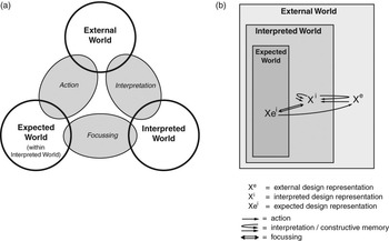
Gero and Kannengiesser (Reference Gero and Kannengiesser2004) have modelled situatedness by specifying three interacting worlds: the external world, the interpreted world and the expected world (Figure 1(a)).
Situatedness as the interaction of three worlds: (a) general model and (b) specialized model for design representations

4.1.1 The external world
The external world is the world that is composed of representations outside the designer or design agent. The notion of ‘external’ is meant in a conceptual sense rather than a physical one. It denotes an environment that contains design artefacts made available for interpretation.
4.1.2 The interpreted world
The interpreted world is the world that is built up inside the design agent in terms of sensory experiences, percepts and concepts. It is the internal representation of that part of the external world that the design agent interacts with. The interpreted world provides an environment for analytical activities and discovery during designing.
4.1.3 The expected world
The expected world is the world of that imagined actions the design agent will produce. It is the environment in which the effects of actions are predicted according to current goals and interpretations of the current state of the world.
4.1.4 Relationships between the three worlds
These three worlds are related together by three classes of interaction. Interpretation transforms variables that are sensed in the external world into sensory experiences, percepts and concepts that compose the interpreted world. Focussing takes some aspects of the interpreted world and uses them as goals for the expected world. Action is an effect which brings about a change in the external world according to the goals in the expected world.
4.1.5 A more detailed framework of design worlds
Figure 1(b) presents a specialized form of this model of design worlds, with the design agent (described by the interpreted and expected world) located within the external world, and with general classes of design representations placed into this nested model. The set of expected design representations (Xei) corresponds to the notion of a design state space, that is, the state space of all possible designs that satisfy the set of requirements. This state space can be modified during the process of designing by transferring new interpreted design representations (Xi) into the expected world and/or transferring some of the expected design representations (Xei) out of the expected world. This leads to changes in external design representations (Xe), which may then be used as a basis for re-interpretation changing the interpreted world. Novel interpreted design representations (Xi) may also be the result of memory (here called constructive memory), which can be viewed as a process of interaction among design representations within the interpreted world rather than across the interpreted and the external world.
Both interpretation and constructive memory are viewed as ‘push-pull’ processes, that is, the results of these processes are driven both by the original experience (‘push’) and by some of the agent’s current interpretations and expectations (‘pull’) (Smith & Gero, Reference Smith and Gero2005). This notion captures two ideas. First, interpretation and constructive memory have a subjective nature, using first-person knowledge grounded in the designer’s interactions with their environment (Bickhard & Campbell, Reference Bickhard and Campbell1996; Clancey, Reference Clancey1997; Ziemke, Reference Ziemke1999). This is in contrast to static approaches that attempt to encode all relevant design knowledge before its use. Anecdotal evidence in support of first-person knowledge is provided by the common observation that different designers perceive the same set of requirements differently (and thus produce different designs). And the same designer is likely to produce different designs at later times for the same requirements. This is a result of the designer acquiring new knowledge while interacting with their environment between the two times.
Second, the interplay between ‘push’ and ‘pull’ has the potential to produce emergent effects, leading to novel and often surprising interpretations of the same internal or external representation. This idea extends the notion of biases that simply reproduce the agent’s current expectations. Examples have been provided from experimental studies of designers interacting with their sketches of the design object. Schön and Wiggins (Reference Schön and Wiggins1992) found that designers use their sketches not only as an external memory but also as a means to re-interpret what they have drawn, thus leading the design in a surprising, new direction. Suwa et al. (Reference Suwa, Gero and Purcell1999) noted, in studying designers, a correlation of unexpected discoveries in sketches with the invention of new issues or requirements during the design process. They concluded that ‘sketches serve as a physical setting in which design thoughts are constructed on the fly in a situated way’. Guindon’s (Reference Guindon1990) protocol analyses of software designers revealed that designing is characterized by frequent discoveries of new requirements interleaved with the development of new partial design solutions. As Guindon puts it, ‘designers try to make the most effective use of newly inferred requirements, or the sudden discovery of partial solutions, and modify their goals and plans accordingly’.
4.2 The situated function–behaviour–structure framework
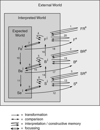
Gero and Kannengiesser (Reference Gero and Kannengiesser2004) have combined the FBS ontology of artefacts with the model of three design worlds, by specialising the description of situatedness shown in Figure 1(b). In particular, the variable X, which stands for design representations in general, is replaced with the more specific representations F, B and S. This results in the situated FBS framework (Figure 2) (Gero & Kannengiesser, Reference Gero and Kannengiesser2004). In addition to using external, interpreted and expected F, B and S, this framework uses explicit representations of external requirements given to the designer by another agent (usually the customer). Specifically, there may be external requirements on function (FRe), external requirements on behaviour (BRe) and external requirements on structure (SRe). The situated FBS framework also introduces the process of comparison between interpreted behaviour (Bi) and expected behaviour (Bei), and a number of processes that transform interpreted structure (Si) into interpreted behaviour (Bi), interpreted behaviour (Bi) into interpreted function (Fi), expected function (Fei) into expected behaviour (Bei) and expected behaviour (Bei) into expected structure (Sei). Figure 2 uses the numerals 1 to 20 to label the resultant set of processes. They do not represent any order of execution.
The situated FBS framework

The 20 processes can be mapped onto eight fundamental design steps (Gero, Reference Gero1990; Gero & Kannengiesser, Reference Gero and Kannengiesser2004).
1. Formulation consists of processes 1–10. It includes interpretation of external requirements, given to the designer by a customer, as function, behaviour and structure through processes 1–3. Requirements are also constructed as implicit requirements generated from within the designer, using constructive memory (processes 4–6). Focussing transfers a subset of the (explicitly and implicitly) required function, behaviour and structure into the expected world (processes 7–9). Expected function and behaviour capture what is often called architecturally significant requirements (Hofmeister et al., Reference Hofmeister, Kruchten, Nord, Obbink, Ran and America2007). In summary, processes 1–9 represent activities that populate the interpreted and expected worlds with design concepts, providing the basis for subsequent transformations of these concepts. Process 10 transforms expected function into additional expected behaviour. The set of expected function, behaviour and structure, resulting from the formulation step, represents the design state space. It includes all the variables and their ranges of values that are relevant for the design task.
2. Synthesis consists of process 11 to generate an instance of structure that is expected to meet the required behaviour, and the externalisation of that structure through process 12. This design step can be viewed as part of a search process through the (previously formulated) state space of all possible instances of structure.
3. Analysis consists of interpretation of externalized structure (process 13) and the derivation of behaviour from that structure (process 14).
4. Evaluation consists of a comparison of expected behaviour and behaviour derived through analysis (process 15).
5. Documentation produces an external representation of the final design solution for purposes of communicating that solution in terms of structure (process 12), and, optionally, behaviour (process 17) and function (process 18).
6. Reformulation type 1 consists of focussing on different structures than previously expected (process 9), resulting in a modified structure state space (a subset of the design state space). Precursors of this process are the interpretation of external structure (process 13), constructive memory of structure (process 6) or the interpretation of new requirements on structure (process 3).
7. Reformulation type 2 consists of focussing on different behaviours than previously expected (process 8), resulting in a modified behaviour state space (a subset of the design state space). Precursors of this process are the derivation of behaviour from structure (process 14), the interpretation of external behaviour (process 19), constructive memory of behaviour (process 5) or the interpretation of new requirements on behaviour (process 2).
8. Reformulation type 3 consists of focussing on different functions than previously expected (process 7), resulting in a modified function state space (a subset of the design state space). Precursors of this process are the ascription of function to behaviour (process 16), the interpretation of external function (process 20), constructive memory of function (process 4) or the interpretation of new requirements on function (process 1).
Similar to the 20 processes, the numbering of the eight design steps does not represent any order of execution. However, the ‘waterfall’ model of software design can be mapped onto the first five fundamental design steps in the situated FBS framework. Here, the numbering of the five design steps can be thought of as specifying a linear sequence of execution. The three types of reformulation provide the potential to break this sequence. Studies of designers have shown that all three of them frequently occur throughout the entire process of designing (McNeill et al., Reference McNeill, Gero and Warren1998; Purao et al., Reference Purao, Rossi and Bush2002).
5 A schema for design method evaluation
The situated FBS framework is independent of the specific artefact and of the specific design processes used. This makes the framework a suitable basis of a general schema for classifying the processes to be supported by design methods. Such a schema would emphasize design interactions and their impact on the resultant artefacts, which allows for method evaluation with respect to their support for situated designing. However, the key ideas conveyed by the situated FBS framework have so far been expressed only informally, using textual, natural-language descriptions. The graphical model in Figure 2 does not fully capture these ideas. A more comprehensive, formal description is required for each of the 20 processes in the situated FBS framework, to provide a schema for systematic analysis and evaluation of design methods.
Applying the FBS ontology to design processes as artefacts, we can re-represent the object-centred description of the 20 design processes as a process-centred one. Most parts of the object-centred model depicted in Figure 2 directly map onto the input and output components of process macro-structure (Sp)Footnote 1. For example, Sp of process 14 in Figure 2 includes (interpreted) object structure (S) as input (i) and (interpreted) object behaviour (B) as output (o). No specific information is given about transformation components, as this is available only at an instance level.
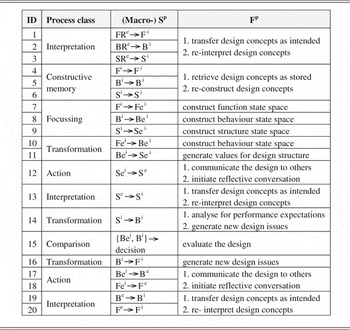
Most of the semantics of a process can be captured by process function (Fp). Table 1 shows the functions (Fp) and macro-structures (Sp) of each of the 20 FBS processes in the context of situated designing.
The 20 FBS processes and their functions in designing (ID numbers refer to the labelling of the processes in Figure 2)

Interpretation processes (1, 2, 3, 13, 19 and 20) can have two different functions. One function is to transfer existing design concepts from one agent to another or to the same agent without a change in the initial meaning of these concepts. This involves bringing external representations into a form that allows processing of these representations by the individual design agent. The other function of interpretation is to re-interpret design concepts, that is, generating concepts and issues that are novel with respect to the ones intended at the time of producing the external representations.
Constructive memory processes (4–6) have a similar set of functions. One function is to retrieve design concepts from some storage space in the same way as they were experienced at the time of storage. Although this may include some computation or transformation, such as refinement or decomposition of design concepts, the results of this process will have a pre-defined relationship with the initial concepts. The other function of the constructive memory processes is to re-construct and thereby modify existing design concepts, which corresponds to the notion of reflection (Schön, Reference Schön1983).
Focussing processes (7–9) have the function to construct the design state space. This includes the construction of the initial design state space (maps onto the formulation step) and subsequent modifications of that space (maps onto the reformulation steps).
Action processes (12, 17 and 18) can have two different functions. One function is to communicate aspects of the design to other stakeholders (agents). Here, the notion of communication is used in its traditional sense of sharing information, based on unambiguous transfer of design concepts. The other function is to initiate reflective conversations, that is, to generate new interpretations based on the ‘backtalk’ of the design situation (Schön, Reference Schön1983) that is formed by the external representations directly or through feedback from other agents.
Processes 10, 11, 14 and 16 may be called ‘FBS transformations’ based on their role as transformers between F, B and S. Process 10 has the function to construct the behaviour state space, and process 11 has the function to generate values within the (previously constructed) structure state space. Process 14 has two functions. One function is to analyse the design with respect to current performance expectations. The other function is to generate new design concepts that can be included as new issues in the current design task. This is also the function of process 16. The comparison process (15) has the function to evaluate the design, based on decision making informed by comparison of expected and interpreted design performance.
It can be seen that some of the functions in Table 1—loosely speaking—relate to non-situated and others to situated aspects of designing. Non-situated aspects are captured by those functions that do not address the potential for change during designing. These comprize the notions of ‘transfer’ (in interpretation processes), ‘retrieval’ (in constructive memory processes) and ‘communication’ (in action processes). Situated aspects of designing describing the potential for change are captured by functions that involve ‘re-interpretation’ (in interpretation processes), ‘re-construction’ (in constructive memory processes) and ‘reflective conversation’ (in action processes).
Table 1 does not include the behaviours (Bp) of the 20 processes. This is because, at the current level of abstraction, they are no different from other processes. This is based on the independence of the situated FBS framework of specific methods or design domains. Not much detailed information about structure (Sp) is available to be able to specialize or quantify general process behaviours (Bp) such as speed, accuracy and cost. An example for such detailed information would be when process structures (Sp) were considered that contain iterations (e.g., when using genetic algorithms in design synthesis). In this case, the behaviour (Bp) ‘rate of convergence’ could be derived that is a specialisation of the behaviour (Bp) ‘speed’. However, as our aim here is to provide a general, rather than an instance-specific, schema, different classes of design processes are distinguished only at the level of function (Fp) and macro-structure (Sp).
6 Evaluating five software design methods
This section presents an evaluation of five design methods: Attribute-Driven Design (ADD) (Wojcik et al., Reference Wojcik, Bachmann, Bass, Clements, Merson, Nord and Wood2006), Siemens Four Views (S4V) (Hofmeister et al., Reference Hofmeister, Nord and Soni2005), Rational Unified Process (RUP)Footnote 2 (Kruchten, Reference Kruchten2004), Business Architecture Process and Organisation (BAPO) (America et al., Reference America, Rommes and Obbink2004), and the Agile Alliance Approach (AAA)Footnote 3 (Agile Alliance, 2007). It is to be noted that there are differences regarding the focus of each method on particular aspects of the artefact (Falessi et al., Reference Falessi, Cantone and Kruchten2007; Hofmeister et al., Reference Hofmeister, Kruchten, Nord, Obbink, Ran and America2007). This is most apparent for AAA that, unlike the other methods, is not directly concerned with architectural aspects. Our evaluation schema can be applied despite these differences, as it is ontologically based rather than instance-specific: It captures all design methods independently of the particular class of artefacts or even the particular design domain.
The evaluation is based on mapping each of the five methods onto the Fp/Sp combinations specified in Table 1. There are two requirements for a method to establish a mapping to a particular combination:
1. The method structure must be described at a level of detail that is reasonable regarding its nature as either a procedural, black-box (implicit or tool-based) or managerial approach.
2. The method must have a function, stated by the method developers or recognized and published by others, that can be mapped onto the specific Fp/Sp combination.
Two difficulties are associated with mapping the methods onto the FBS evaluation schema. First, the terms and concepts specified by a particular method are often not well defined, and their mapping on to the ontological constructs of function, behaviour and structure usually requires some interpretation. A starting point for addressing this issue has been Kruchten’s (Reference Kruchten2005) mapping of RUP terms on to the FBS ontology. Second, different aspects in a method are described at varying levels of depth. Some activities in designing are not, or only briefly, mentioned. We interpret these ‘shallow’ descriptions as implicit methods (see Section 3) performed by human agents. They are located at the lower bounds of what can be validly termed a method.
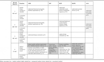
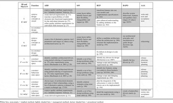
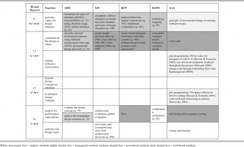
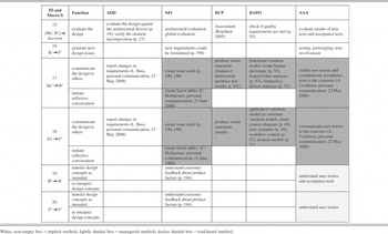
To increase the validity of our evaluation, we have invited key researchers involved in the development of each of the five design methods to provide critical feedback. They include Len Bass (for ADD), Christine Hofmeister (for S4V), Philippe Kruchten (for RUP), Pierre America (for BAPO) and Alistair Cockburn (for AAA). Tables 2–5 show the mappings we established, taking into account the feedback we received from these experts. The remainder of this section compares our mappings for the process classes of action, FBS transformation, evaluation, focussing, interpretation and constructive memory.
Evaluation of five software design methods (Part 1)

White, non-empty box = implicit method; lightly shaded box = managerial method; darker shaded box = procedural method.
Evaluation of five software design methods (Part 2)

White box, non-empty = implicit method; lightly shaded box = managerial method; darker shaded box = procedural method.
Evaluation of five software design methods (Part 3)

White, non-empty box = implicit method; lightly shaded box = managerial method; medium shaded box = procedural method; dark shaded box = tool-based method.
Evaluation of five software design methods (Part 4)

White, non-empty box = implicit method; lightly shaded box = managerial method; darker shaded box = tool-based method.
6.1 Method support for action
We have specified two possible functions of methods related to action: communicating the design and initiating reflective conversation. All five methods support communicating external structure (Se) (Table 4). A range of tools are available for most of them, providing extensive features for visualising software architecture (Falessi et al., Reference Falessi, Cantone and Kruchten2007) or for editing code. Most methods also support communicating external behaviour (Be) and external function (Fe) (Table 5). Support for initiating reflective conversation has been recognized or claimed for S4V and AAA (Tables 4 and 5).
6.2 Method support for FBS transformations and evaluation
FBS transformations and evaluation have been the focus of the study by Hofmeister et al. (Reference Hofmeister, Kruchten, Nord, Obbink, Ran and America2007). Most of the transformations are supported by the five methods, particularly the transformation of Fei to Bei (Table 3) and of Bei to Sei (Table 4). Both of them are supported by ADD, S4V, RUP and BAPO through procedural approaches. AAA uses an implicit approach and a managerial approach for FBS transformations and evaluation, respectively. The transformation of Si to Bi (Table 4) is supported by all methods in various ways, including implicit (ADD, S4V and BAPO), procedural (ADD) and tool-based (RUP and AAA) approaches. Support for generating new design issues through transformations of Si to Bi (Table 4) and of Bi to Fi (Table 5) is provided by S4V and AAA in implicit ways. The process of software evaluation (Table 5) is supported by all five methods, also using implicit approaches.
6.3 Method support for focussing
ADD, S4V and RUP provide support for focussing on function, behaviour and structure (Table 3). Here, ADD and S4V use procedural approaches, and RUP uses a mixture of implicit, managerial and procedural approaches. BAPO offers support only for focussing on function (in a procedural way), and AAA only for focussing on function and behaviour (in a managerial way).
6.4 Method support for interpretation
Method support for interpretation is restricted to lightweight approaches. Most methods view interpretation simply as ‘understanding’ design requirements in the way stated or implied by the customer (Tables 2 and 5). This does not mean that new requirements cannot be included during the process of designing, but they are assumed to be generated externally and not through re-interpretation by the design agent. This is often driven by reflective conversation, which is supported by S4V and AAA, as shown in Section 6.1. Generating new design concepts through re-interpretation is supported only by AAA (Tables 2, 4 and 5).
6.5 Method support for constructive memory
Current approaches to memory systems are based on the paradigm of static retrieval rather than dynamic re-construction. As a result, all current methods are limited to provide active support only for static operations on design concepts. Here, ADD, S4V, RUP and BAPO offer the most extensive support, covering function (Table 2), behaviour as well as structure (Table 3). In contrast, AAA does not address the decomposition or refinement of function. It offers managerial support for generating behaviour through test design, and some procedural support for modifying structure based on strategies of refactoring (Kerievsky, Reference Kerievsky2004).
7 Conclusion
This paper contributes to research in software design methodology in three ways.
First, the paper proposes an ontological basis for understanding the notion of a design method, addressing three fundamental aspects:
1. Method function, capturing the specific design activities targeted (‘what the method is for’). Design activities are represented in a generic way on the basis of a uniform process framework.
2. Method behaviour, capturing performance (‘what and how well the method does’). It provides operational criteria for evaluating instances of methods.
3. Method structure, capturing the internal composition of the method (‘the nature or essence of the method’). This allows grouping of methods in separate classes independently of the domain of application.
Method function and method structure are the major elements of an ontological schema for comparing and evaluating design methods, independently of the different terms used in these methods. Our schema is more detailed than earlier approaches, and is based on recent insights in the general area of design science that are subsumed in the notion of situatedness. Research in software engineering is only beginning to embrace this notion. We see our work as a systematic framework for the increasing research efforts in this area.
Second, the paper shows how the ontological schema allows evaluating design methods independently of their particular views of the artefact, thus concentrating on more fundamental similarities and differences. A benefit of this is an easier combination of methods that would otherwise appear unrelated or even conflicting. The increasing use of agile techniques within software architecture design can be seen as an example of method combination. Our work provides a tool for further progress towards integrating different approaches, which may even originate from domains other than software design.
Third, the ideas presented in this paper can be used for classifying future research directions in software design methodology, oriented to method function, behaviour or structure. Function-oriented research aims at discovering new connections or refining existing connections between design activities and methods. This may fill some of the empty boxes in Tables 2–5 without necessarily expanding or modifying method structure. For example, the function to initiate reflective conversation may be ascribed to some of the methods currently not associated with that function. Behaviour-oriented research is mainly based on empirical studies. Here, instances of methods are analysed for a specific problem in a specific context, to obtain quantitative measures that allow assessing their performance and deducing general statements on effectiveness and efficiency. Structure-oriented research aims to generate new methods or modify existing methods for supporting a specific design activity. For example, existing lightweight methods for some design activities may be augmented by new procedural or tool-based support.
Research efforts of the three orientations should be regarded as complementary as they address different yet related aspects of software design methods. The ontological basis developed in this paper provides a unifying framework for locating these efforts.
Acknowledgements
We express our gratitude to Pierre America, Len Bass, Alistair Cockburn, Christine Hofmeister and Philippe Kruchten for critically reviewing an earlier draft of the paper. Their comments and suggestions have significantly improved the quality of this work.
NICTA is a national research institute with a charter to build Australia’s pre-eminent Centre of Excellence for Information and Communications Technology (ICT). NICTA is building capabilities in ICT research, research training and commercialisation in the ICT sector for the greater benefit of the nation. NICTA is funded by the Australian Government as represented by the Department of Broadband, Communications and the Digital Economy and the Australian Research Council through the ICT Centre of Excellence program.