I. INTRODUCTION
Energy crisis is one of the main barriers constraining the development of human societies. Currently, about 80% of world primary energy consumption comes from fossil fuels, such as coal, oil, and gas, which are finite and generate large amounts of greenhouse gases during use. Reference Jacob and Bruno1,Reference Wang, Wang, Huang, Li, Peng and Ding2 To address the energy issues, further increasing the share of energy produced by renewable energy technologies and improving the energy efficiency of fossil fuels are two effective ways.
In various industrial processes, there is a considerable amount of waste heat emitted out in the form of high-temperature gases or liquids. For example, the steel-making industry with high energy consumption emits essentially 50% of input energy in the form of high-temperature waste gas. Reference Maruoka, Sato, Yagi and Akiyama3 And the temperature of the waste heat varies from low grade (e.g., 308–313 K in power plants) to very high one (e.g., 1873 K in iron-making and steel-making plants). Reference Wang, Wang, Huang, Li, Peng and Ding2 However, for many industrial processes, one challenge for the use of waste heat is its intermittence. For instance, a Linz–Donawitz converter of steel-making periodically emits waste gas above 1873 K. Reference Maruoka, Sato, Yagi and Akiyama3 Thermal energy storage (TES), which allows the storage of heat or cold for later use, is one feasible solution to this challenge. Particularly, latent heat TES (LHTES), utilizing the latent heat absorbed or released during the melting or solidification of phase-change materials (PCMs) for TES, attracts much attention. The most notable feature of LHTES is that it can store heat for dozens of times as many as sensible heat TES, which uses the sensible heat produced through the temperature change of single-phase materials (e.g., water or concrete) for TES. In LHTES, the PCMs bear the function of TES.
To harvest industrial waste heat, in accordance with the temperature range of a certain kind of waste heat, the PCMs with matching phase-change temperature are needed. Up to date, most researches have focused on low-temperature PCMs, such as paraffin Reference Su, Darkwa and Kokoginanakis4–Reference Francesco and Enico12 and hydrous salts, Reference Kenisarin13–Reference Tamme, Laing and Steinmann20 which are for domestic heating/cooling applications. Nevertheless, high-temperature PCMs with melting temperatures above 573 K or even more than 1273 K have been less developed and their types are basically limited to molten salts (such as alkali metal nitrates) Reference Kenisarin13 or metals. The disadvantage of molten salts is their inherent low thermal conductivity, resulting in undesirably long charge/discharge time. In comparison, metallic PCMs possess thermal conductivities of at least two orders of magnitude higher than those of molten salts with comparable latent heat density and good thermal stability. However, for liquid–solid metallic PCMs, the encapsulation problem must be solved before use due to liquid metal corrosion. For instance, for Al–Si based PCMs, one of the most investigated metallic PCMs, stainless steel is one common packaging material. Reference Cui, Peng and Jiang21 But, encapsulation materials for higher temperature PCMs were rarely reported. In literature, Akiyama et al. Reference Maruoka, Sato, Yagi and Akiyama3 proposed copper balls (3 mm in diameter) as the PCM to recover waste heat of the converter gas, which were encapsulated by nickel film (by using an electroplating method) with/without an insertion of carbon (by a commercial spraying process) or ruthenium (by using an electroplating method) as the inhibition layer. They stated that copper balls with nickel film and an inactive inhibition layer behaved well against copper volume expansion during melting. But the un-uniform carbon layer deposited leaded to the leakage of copper easily. Reference Maruoka, Sato, Yagi and Akiyama3,Reference Maruoka, Asao, Miyako, Nakamoto and Akiyama22–Reference Akiyama, Oikawa, Shimada, Kasal and Yagi24 Kisi et al. Reference Sugo, Kisi and Cuskelly25 also selected copper as the PCM and prepared a Cu–Fe matrix with Cu particles (lower than 80 μm in diameter) dispersed in immiscible Fe matrix by a powder metallurgy process. But the thermal stability of the as-reported Cu–Fe material could only meet the requirement of short-term thermal cycles.
In our previous work, Reference Zhang, Li, Chen, Xiang, Ma, Xu and Ma26 a novel bilayer (chromium and nickel) shell material was proposed to coat copper balls. Such structure was designed on the basis of the idea that because of the complete mutual solubility of copper and nickel, the middle chromium layer was selected to function as the insulation material between copper and nickel, while the nickel layer was used to improve the resistance to oxidation. The designed Cu@Cr@Ni capsules were prepared by a novel chromium periodic-barrel electroplating method and nickel barrel-plating method. For details, please check them in Ref. Reference Zhang, Li, Chen, Xiang, Ma, Xu and Ma26. The Cu@Cr@Ni capsules showed no leakage after 1000 charging–discharging thermal cycles between 1323 and 1423 K. Reference Zhang, Li, Chen, Xiang, Ma, Xu and Ma26 From this result, it can be concluded that a chromium–nickel shell is a durable encapsulation material for high-temperature application. Also, the metallic chromium–nickel shell with a high thermal conductivity would facilitate the efficient transfer from the heat transfer fluid (HTF) to the PCM. In this work, we present a numerical study of the melting process of the Cu@Cr@Ni capsules in a LHTES unit during the recovery of converter gas, i.e., the thermal energy charging behavior of the Cu@Cr@Ni capsules. The purpose is to investigate the heat transfer properties between PCMs and high-temperature waste gas, and the weakening effect of the PCMs on the periodical temperature fluctuation of waste gas.
Generally speaking, the high thermal conductivity of metallic PCMs makes them superior in thermal energy transfer compared to organic and salts PCMs, but there are few experimental and numerical investigations on the TES of metallic PCMs in LHTES systems. In Ref. Reference Yagi and Akiyama27, Yagi and Akiyma studied the heat storage process of two inorganic salts (KNO3–47 mol% NaNO3, and NaCl) and four metallic PCMs (Pb, Al, Al–12.6 wt% Si, and Al–25.1 wt% Si), and indicated that a uniform temperature would exist in the metallic PCM capsules, which was distinguishing from the inorganic salt PCMs. Blanco-Rodríguez et al. Reference Blanco-Rodríguez, Rodríguez-Aseguinolaza, Gil, Risueño, Aguanno, Loroño and Martín28 experimentally investigated the charging and discharging processes of Mg–51 wt% Zn eutectic alloy as PCM in TES. Their results revealed that the high thermal conductivity of Mg–51% wt% Zn eutectic alloy (75 W/m K at solid phase and 35 W/m K at liquid phase) makes it an ideal option for the evaporation process of water in direct steam generation applications. And Liu et al. Reference Yang, Tan and Liu29 compared the phase-change processes of a typical low melting point metal gallium and a typical paraffin eicosane, and indicated that the natural convective flow in liquid gallium is more intensive since its velocity is several times larger than that in eicosane, which was caused by the high thermal conductivity of gallium. However, there are no reports on the thermal storage properties of metallic PCMs possessing as high temperature and thermal conductivity as copper in LHTES system. Therefore, it is strongly desirable to clarify the heat transfer and melting modes caused by the high thermal conductivity of metals (e.g., copper, 387.6 W/m K at solid phase and 163.8 W/m K at liquid phase).
Moreover, for the LHTES unit with spherical PCMs, fixed packed bed is the commonest and a suitable choice when a gas is used as HTF. Its simple structure means simple process and low cost. The arrangement of spherical capsules in the fixed bed could be random or special. For example, Xia et al. Reference Xia, Zhang and Wang30 conducted a comprehensive numerical analysis about the fixed bed with PCMs, and revealed that a random packing was more favorable for heat storage and retrieval than any special one. The modeling of the thermal storage of fixed beds can be basically subdivided into two wide groups. The first group includes models taking the instantaneous solid and liquid phases as the same phase, i.e., the so-called single-phase models. Reference Nemec and Levecb31 The second group includes models in which the fixed bed is represented by two distinct phases, i.e., the two-phase models. The two-phase models included basically three categories of Schumann’s model, Reference Schumann32 the continuous solid phase model, Reference Arkarv and Medved33 and the concentric dispersion model. Reference Regin, Solanki and Saini34 Comparing their utilizations, the continuous solid phase model is more convenient than the concentric dispersion model, and more accurate than the single-phase models. Thus, the continuous solid phase model has been extensively used to study the thermal performance of the packed bed systems. Reference Xia, Zhang and Wang30–Reference Bellan, Gonzalez-Aguilar, Remero, Rahman, Goswami, Stefanakos and Couling36 However, none of these models could reveal the accurate flow field as the HTF flows through the voids among the PCM spheres, and thus these models can not describe the difference in the arrangement of PCM spheres if the packed bed LHTES systems have the same loading ratio of PCMs. In this study, the turbulence model (realizable k–ε model) is used to investigate the influence of the turbulent flow, and the solidification–melting model is adopted for the description of the phase transition. The realizable k–ε model and the solidification–melting model as well as the enthalpy-porosity model proposed by Voller et al. Reference Voller and Prakash37,Reference Brent, Voller and Reid38 could solve the question of the flow field between the PCM spheres, simulate the motion in the mushy region, and exhibit the heat transfer more accurately.
Therefore, the randomly packed bed and the enthalpy-porosity model are adopted in the present work. And different inlet velocities and periods of inlet temperature fluctuation of HTF are designed to reveal the performance of the Cu@Cr@Ni capsules as thermal storage unit in recovering the waste heat from high-temperature converter gas and attenuating the fluctuation of the inlet temperature by numerical simulation. During the simulation, the system was assumed to comply with a two-dimensional model. And the numerical simulation was solved in ANASYS FLUENT (a commercial software used for computational fluid dynamics) environment.
II. NUMERICAL MODELING
A. The physical model
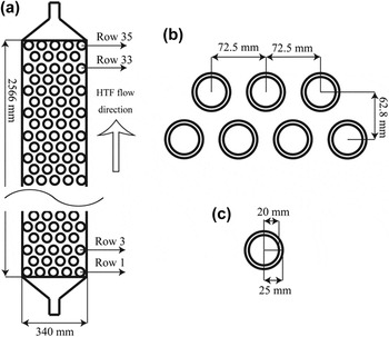
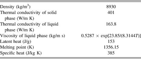
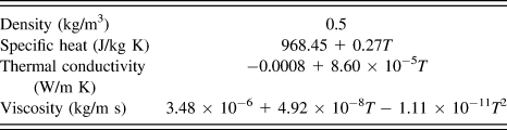
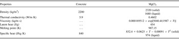
Based on the literature, Reference Xia, Zhang and Wang30,Reference Bellan, Gonzalez-Aguilar, Remero, Rahman, Goswami, Stefanakos and Couling36 the 3D model can be transformed to 2D model to decrease the calculation amount under the condition that the accuracy of the simulation result is ensured, the randomly packed bed can promote the turbulent flow to enhance the heat transfer between HTF and PCMs and decrease the cost. Fig. 1 shows the physical model for the present numerical analysis. The insulated cylindrical tank is of 340 mm diameter and 2566 mm height. The filled spherical Cu@Cr@Ni capsules are of an inner diameter of 40 mm and an outer diameter of 50 mm. The spherical PCM capsules with 72.5 mm distance between two neighboring spheres are loaded in thirty-five layers. The distance between two neighboring layers is 62.8 mm. The physical properties of Cu@Cr@Ni and converter gas as HTF are shown in Tables I and II, respectively. Table III shows the physical properties of concrete and MgCl2.
Schematic diagrams of the two-dimensional physical model of the fixed bed (a), the arrangement of PCMs capsules (b) and the structure of a single spherical core–shell capsule (c).

Physical properties of Cu@Cr@Ni.

Physical properties of the waste gas.

Physical properties of concrete and MgCl2.

B. Mathematical formulation and numerical modeling
The simulation is based on the following assumptions:
-
(i) The radiant heat transfer is neglected.
-
(ii) The heat transfer between the fluid and the wall of the tank is neglected.
-
(iii) The heat transfer between the wall of the tank and the ambient is neglected.
-
(iv) The flow of HTF is incompressible and Newtonian.
The mathematical formulation of the phase-change problem includes mass, momentum, and energy conservation equations. Reference Xia, Zhang and Wang30,Reference Voller and Prakash37–Reference Shatikian, Ziskind and Letan39 The mass conservation equation (the continuity equation) is formulated as:
 $${{\partial \rho } \over {\partial t}} + {{\partial \left( {\rho {u_x}} \right)} \over {\partial x}} + {{\partial \left( {\rho {u_y}} \right)} \over {\partial y}} = 0\quad ,$$
where ρ is the density, u x is the x-direction velocity, and u y is the y-direction velocity.
In terms of the formation of liquid during the phase change, fluid flow occurs in the liquid phase and the mushy zones, which are governed by the following set of momentum conservation equations:
 $${{\partial \left( {\rho {u_x}} \right)} \over {\partial t}} + \nabla \left( {\rho {u_x}\vec u} \right) = - {{\partial P} \over {\partial x}} + \nabla \left( {\mu \nabla {u_x}} \right) + {S_x}\quad ,$$
 $${{\partial \left( {\rho {u_y}} \right)} \over {\partial t}} + \nabla \left( {\rho {u_y}\vec u} \right) = - {{\partial P} \over {\partial y}} + \nabla \left( {\mu \nabla {u_y}} \right) + {S_y} + {S_{\rm{b}}}\quad ,$$
where
 $\vec u$
, P, and μ represent the velocity vector, pressure, and viscosity of the PCM, respectively; and S
x
, S
y
, and S
b are the source terms.
S x and S y are used to modify the momentum equations in the mushy zones, which are governed by the equations presented below:
 $${S_x} = A{u_x}\quad ,$$
 $${S_y} = A{u_y}\quad ,$$
where A decreases from a large value to zero as the liquid fraction increases in the mushy zones. In liquid region, A will dominate the transient, convective, and diffusive terms of momentum equations. A is defined below:
 $$A = - C{{{{\left( {1 - \gamma } \right)}^2}} \over {{\gamma ^3} + \varepsilon }}\quad ,$$
where γ is the liquid fraction. And ε is introduced to avoid the division by zero, which is a constant and set at 0.001. C will depend on the morphology of the porous media. The value of C is in the range from 104 to 107, but normally taken as 105.
The liquid fraction, γ, is given by the following equation:
 $$\gamma = \left\{ {\matrix{ 0 & {T \;\lt\; {T_{{\rm{solidus}}}}} \cr {{{T - {T_{{\rm{solidus}}}}} \over {{T_{{\rm{liquidus}}}} - {T_{{\rm{solidus}}}}}}} & {{T_{{\rm{solidus}}}} \;\lt\; T \;\lt\; {T_{{\rm{liquidus}}}}} \cr 1 & {T > {T_{{\rm{liquidus}}}}} \cr} } \right.\quad .$$
The source term S b in Eq. (3) is a buoyancy term, which is used to induce the natural convection in the system. The buoyancy source term is given by
 $${S_{\rm{b}}} = {{\rho g\beta \left( {h - {h_{{\rm{ref}}}}} \right)} \over {{C_{\rm{p}}}}}\quad ,$$
where g is the gravitational acceleration, β is the thermal expansion coefficient, and h ref is the enthalpy at a reference temperature, and C p is the specific heat at a constant pressure.
The energy conservation equation takes the following form:
 $${\partial \over {\partial t}}\left( {\rho H} \right) + \nabla \left( {\rho \vec uH} \right) = \nabla \left( {k\nabla T} \right) + {S_{\rm{h}}}\quad ,$$
where H is the enthalpy, k is the thermal conductivity, S h is the energy source term. The enthalpy, H, is computed as the sum of the sensible enthalpy h, and the latent heat ΔH:
 $$H = h + \Delta H\quad .$$
The sensible enthalpy h is defined below:
 $$h = {h_{{\rm{ref}}}} + \int_{{T_{{\rm{ref}}}}}^T {{C_{\rm{p}}}\,{\rm{d}}T} \quad ,$$
where T ref stands for the reference temperature.
The latent heat ΔH can be given by
 $$\Delta H = \gamma L\quad ,$$
where L is the specific latent heat of the PCM.
When the PCM is in liquid phase, nature convection may occur which enhances the heat transfer. The nature convection effect of the liquid PCM is taken into account by using the following effective thermal conductivity of liquid PCM: Reference Xia, Zhang and Wang30
 $${k_{{\rm{p}}{\rm{.conv}}}} = 0.18{k_{\rm{p}}}{\rm{R}}{{\rm{a}}^{0.25}}\quad ,$$
where the Rayleigh number, Ra, is defined as gβ(T p − T m) (d/2)3/vα, in which v and α are the kinematic viscosity and thermal diffusivity, respectively.
In terms of the convection diffusion in the mushy zones, the source term S h is governed by
 $${S_{\rm{h}}} = {\partial \over {\partial t}}\left( {\rho \Delta H} \right) + \nabla \left( {\rho \vec u\Delta H} \right)\quad .$$
The performance of the latent heat storage system filled with the Cu@Cr@Ni capsules is numerically simulated by using the Mole-8.5 supercomputing system developed by Institute of Process Engineering, Chinese Academy of Sciences. Reference Wang and Ge40 The solution methods in FLUENT are set as follows: The pressure-implicit with splitting of operators algorithm is used for the pressure–velocity coupling. The least squares cell based algorithm is used for the gradient spatial discretization. The pressure staggering option algorithm is used for the pressure spatial discretization. The second order upwind is adopted for momentum and energy equations to ensure accuracy. Convergence criteria of 10−5 is set for momentum equation, 10−7 for the energy equation, and 10−4 for the continuity equation at each time step.
C. Boundary and initial conditions
The initial condition in the model is that the temperature of HTF is the same as that of the PCM (
 ${T_{{\rm{HTF}}}} = {T_{{\rm{PCM}}}} = {T_{{\rm{ini}}}} = 773.15\;{\rm{K}}$
).
The boundary conditions are as follows:
 $${\rm{At\ inlet,\ }}{T_{{\rm{HTF}}}} = {T_{{\rm{in}}}},\;{u_y} = {u_{{\rm{in}}}},{u_x} = 0,\;t > 0\quad .$$
 $${\rm{At\ outlet}},\;{{\partial {T_{\rm{f}}}} \over {\partial {\rm{y}}}} = 0,\;{{\partial {u_y}} \over {\partial y}} = 0,\;t > 0\quad .$$
The wall of the heat storage tank is adiabatic, and the boundary condition is presented below:
 $${{\partial {T_{\rm{f}}}} \over {\partial x}} = 0,\;{{\partial {T_y}} \over {\partial y}} = 0,\;{u_x} = {u_y} = 0,\;t > 0\quad .$$
In the study, the grid and time-step independences have been checked, three time steps viz.: 0.01, 0.05, and 0.1 s, three different grid cell amount viz.: 258,060, 301,010, and 385,600, were tested. As a compromise between the calculating time and the accuracy, 0.05 s was adopted as time step and 301,010 cells was chosen to carry out the numerical simulation.
III. RESULTS AND DISCUSSION
A. Effect of different heat storage materials
In the section, three different heat storage materials, Concrete, MgCl2, Cu@Cr@Ni capsule, are used to recover the waste heat of the converter gas. The inlet temperature of HTF was kept constant at 1600 K (the melting points of nickel and chromium are 1726 and 2103 K, respectively), and the inlet velocities were set as 5 m/s.
The quality of the heat storage system can be evaluated by the energy transfer efficiency η, which is defined as the ratio of the transferred heat to the maximal transferable heat: Reference Yang, Zhang and Xu41,Reference Koushsou, Strub, Lasvignottes, Jamil and Bédécarrats42
 $$\eta = {{{\rho _{\rm{f}}}{q_{\rm{v}}}{C_{\rm{f}}}\left( {{T_{{\rm{f,in}}}} - {T_{{\rm{f,out}}}}\left( t \right)} \right)} \over {{\rho _{\rm{f}}}{q_{\rm{v}}}{C_{\rm{f}}}\left( {{T_{{\rm{f,in}}}} - {T_{{\rm{f,ini}}}}} \right)}} = {{{C_{{\rm{f,in}}}}{T_{{\rm{f,in}}}} - {C_{{\rm{f,out}}}}{T_{{\rm{f,out}}}}(t)} \over {{C_{{\rm{f,in}}}}{T_{{\rm{f,in}}}} - {C_{{\rm{f,ini}}}}{T_{{\rm{f,ini}}}}}}\quad .$$
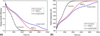
In the present study, the calculated energy transfer efficiency and outlet temperature are shown in Fig. 2.
The energy transfer efficiency (a) and outlet temperature (b) versus time with different heat storage materials.

As shown Fig. 2, the energy transfer efficiency decreases with the increase of the time and the energy transfer efficiency of the heat storage system filled with Cu@Cr@Ni capsule is up to 91%, that filled with concrete or MgCl2 is lower than 89%. At the same moment, the energy transfer efficiency of Cu@Cr@Ni capsule is higher than that of concrete or MgCl2, which is due to the higher heat conductivity of Cu@Cr@Ni capsule than those of concrete and MgCl2, the higher conductivity means the higher rate of heat transfer between HTF and PCMs and the lower loss of the heat energy emitted. The property also results in the lower outlet temperature with Cu@Cr@Ni as heat storage unit than that with concrete or MgCl2.
B. Effect of inlet velocity
To study the effect of inlet velocity on the thermal storage behavior of the Cu@Cr@Ni capsules PCMs, the inlet temperature of HTF was kept constant at 1600 K, and the inlet velocities were set as 1.25, 2.5, 3.75, and 5 m/s.
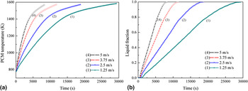
As shown in Fig. 3, the mean temperature and liquid fraction of PCM increase with increasing inlet velocity. The higher the inlet velocity is, the higher the temperature of the PCM rises [see Fig. 3(a)], and the earlier the phase transition is finished [see Fig. 3(b)]. When the inlet velocity is 1.25 m/s, the transition from the solid to liquid phase of the PCM is finished in 29,400 s [see Fig. 3(b)]. As the inlet velocity increased from 1.25 to 5 m/s, the time for the phase transition was reduced in 36–72%. This is because a higher inlet velocity of HTF would lead to a higher surface heat transfer coefficient (SHTC), and thereby the heat transfer rate between PCMs and HTF becomes faster. As a result, more thermal energy can be transferred from HTF to PCM.
The mean PCM temperature (a) and liquid fraction (b) versus time at different inlet velocities.

After the temperature of the PCM reaches the melting point of copper (1356 K), the PCM begins to transform from solid to liquid phase. With increasing time, the fraction of liquid in the PCM begins to be the majority. And during the melting of the PCM and after the ending of the transition, the slope of the PCM temperature curve becomes markedly reduced, because the temperature of the solid copper increases much faster than the liquid copper under the same heat flux due to the difference of thermal conductivities between liquid and solid coppers.
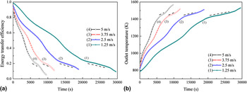
Figure 4(a) reveals that the energy transfer efficiency decreases with the increase in the time and inlet velocity. And from Fig. 4(b), the change trend of the outlet temperature with time can be divided into three stages at different inlet velocities: the sensible heat storage before the ending of phase transition, latent heat storage and sensible heat storage after the ending of phase transition, respectively. The increasing rate of temperature in the third stage is less than that in the first stage because the temperature difference between the HTF and PCMs, the driving force of heat transfer, is smaller in the third stage than that in the first stage. After the mean temperature of PCM reaches the melting point of copper in the third stage, there is a short melting platform, which becomes shorter with increasing inlet velocities. Due to the high thermal conductivity of copper capsules, the temperature of the melting platform slowly increases instead of being a constant. The outlet temperature at higher inlet velocity becomes higher at the same time, which is attributed to two reasons. The first reason is a decrease in the residence time of the HTF flowing through the PCM layer due to an increase in the velocity of HTF, and thus, complete heat exchange will not occur. The second reason is that an increase in the input thermal energy due to an increase in the velocity of HTF leads to an increase of the outlet temperature. Reference Nomura, Tsubota, Oya, Okinaka and Akiyama43 The change trend of energy transfer efficiency is opposite to that of the outlet temperature.
The energy transfer efficiency (a) and outlet temperature (b) versus time at different inlet velocities.

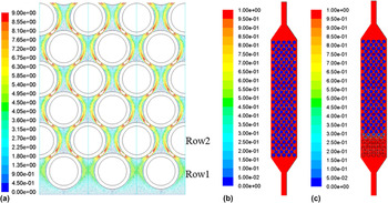
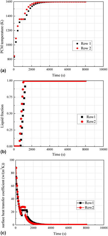
Figures 5(a)–5(c) shows the local contour of the velocity vector at 500 s, and the liquid profiles of the fixed bed at 500 and 5000 s, respectively, when the inlet velocity is 1.25 m/s. It is obvious that the velocity vector in Row 1 is less than that in Row 2 [see Fig. 5(a)], resulting in the lower PCM temperature, smaller liquid fraction and lower SHTC in Row 1 than that in Row 2 at 500 s [see Figs. 6(a)–6(c), respectively]. From the liquid profile, it could be seen that the capsules melted from the bottom and only two rows of the capsules were at the liquid/solid interface, implying that the capsules only partly melted.
The local contour of the velocity vector at 500 s (a). The liquid profile at 500 s (b) and 5000 s (c) at 1.25 m/s, respectively.

PCM temperature (a), liquid fraction (b), and the surface heat transfer coefficient (c) of Row 1 and Row 2 versus time at 1.25 m/s.

From Fig. 6(b), it is seen that the capsules at Rows 1 and 2 melted within about 420 s. According to Fig. 6(c), before 1000 s, the SHTC of Row 1 is smaller than that of Row 2. Therefore, both the mean temperature of the PCM and the liquid fraction at Row 1 are lower than those of Row 2.
The detailed variations of the SHTC of the capsule walls for Rows 1 and 2 are shown in Fig. 6(c). The reasons for these variations are stated as following. Reference Archibold, Gonzalez-Aguilar, Rahman, Goswami, Romero and Stefanakos44 (i) In the initial stage, the change of SHTC is mainly correlated to the temperature difference between HTF and PCMs. The decrease of the temperature difference will lead to the decrease of the SHTC. (ii) In the second stage, the sharp increase of SHTC is due to the presence of the natural convection which can be attributed to the appearance of liquid PCMs. (iii) In the third stage, the SHTC is a constant during the phase transition. (iv) In the last stage, the phase transition ends, and the SHTC is also mainly in correlation with the temperature difference between HTF and PCMs. Therefore, the SHTC decreased due to the decreasing temperature difference.
Before 1000 s, the SHTC of Row 2 is higher than that of Row 1, because the value of the velocity plays a decisive role in it. After 1000 s, the SHTC of Row 2 is lower than that of Row 1. The reason for this phenomenon is that the phase transition ends and the temperature difference plays a decisive role in it.
C. Effect of the period of inlet temperature fluctuation
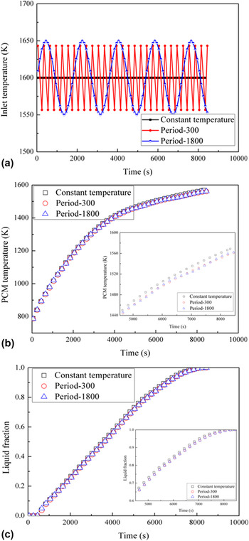
In a real steel-making process, the temperature of the converter gas is not constant because oxygen gas is blown into the converter periodically. In this simulation, the inlet velocity is set as 5 m/s, and the periods of the inlet temperature fluctuation are set as 300 and 1800 s, respectively. It is assumed that the inlet temperature is a sinusoidal function of time, Reference Charvat, Klimes, Stetina and Ostry45 and the functions of the inlet temperature changes with time are given as following, respectively:
 $${T_1} = 50\,\sin {{2 \times 3.1415926t} \over {300}} + 1600\quad ,$$
 $${T_2} = 50\,\sin {{2 \times 3.1415926t} \over {1800}} + 1600\quad .$$
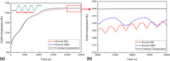
Figure 7(a) shows the inlet temperature change trends under different periods. As seen from Figs. 7(b) and 7(c), and their insets, the mean temperature and liquid fraction of the PCM are quite insensitive to the period of the inlet temperature fluctuation. The mean temperature of PCM at constant inlet temperature is only 8.4 K, higher than that at fluctuant inlet temperature [see the inset of Fig. 7(b)]. Figure 8 displays the outlet temperature of HTF with time when the inlet temperature varies as shown in Fig. 7(a), which intends to demonstrate the effect of the period of the HTF temperature fluctuation on the periodic melting behavior of PCM. Over the whole process, the outlet temperatures under the three conditions are basically the same [see Fig. 8(a)]. Figure 8(b) shows the enlarged section marked by the box in Fig. 8(a) after the outlet temperatures reaches a steady state around 1600 K. The fluctuation ranges are 1588–1593 K at the fluctuation period of 1800 s, and 1587–1592 K at the fluctuation period of 300 s, respectively. Compared to the initial amplitude of the inlet temperature fluctuation, ±50 K, such a sharp mitigation of the outlet temperature fluctuation amplitude clearly reflects the thermal damping efficacy of the PCM filled in the fixed bed to the cyclic heat load. Reference Ho and Chu46,Reference Tan and Ho47 The decrease in the outlet temperature fluctuation range can reduce the damage to the equipment due to the expansion caused by heating and the contraction caused by cooling, contributing to the accurate control and the use of the outlet temperature.
When the inlet temperature varies as shown in (a), the time dependences of PCM temperature (b) and liquid fraction (c), respectively.

Outlet temperature of HTF with time (a) when the inlet temperature varies as shown in (a), and the section in the marked box in (a) is enlarged as in (b).

IV. CONCLUSIONS
The thermal energy charging process of spherical Cu@Cr@Ni phase-change capsules in a LHTES system was numerically investigated. The effects of the inlet velocity and period of inlet temperature fluctuation were examined. The following conclusions can be drawn:
-
(1) The higher the inlet velocity is, the more rapidly the outlet and mean temperatures of PCM increase, and consequently, the earlier the phase transition happens. However, the energy transfer efficiency becomes lower with higher inlet velocities. So, to obtain high energy transfer efficiency and high waste heat recovery efficiency, the measures could be to increase the amount of PCM and decrease the inlet velocity to prolong the residence time of the HTF flowing through the PCM. At a certain inlet velocity, the increase rates of the temperature and the liquid fraction of the PCM capsules in Row 2 are higher than those in Row 1 due to the more intense turbulent perturbation.
-
(2) The mean temperature and liquid fraction of the PCM and the outlet temperature of HTF are quite insensitive to the period of the inlet temperature fluctuation. The variations of the three parameters subjected to a periodical inlet temperature fluctuation are approximately equal to those with a constant inlet temperature. The amplitude of the inlet temperature fluctuation, ±50 K, was sharply reduced to 5 K due to the thermal damping efficacy of the PCM. Although the inlet temperature is rather fluctuant, a constant or slightly fluctuant outlet temperature could be obtained after HTF passes through the PCM.
NOMENCLATURE

ACKNOWLEDGMENTS
This work was financially supported by the National Natural Science Foundation of China (Grant Nos. 51274182, 51471158, 61274015, and U1407105). Partial work was also supported by Open Funding Project of the State Key Laboratory of Biochemical Engineering (Grant No. 2014KF-04), National Key Research and Development Program (Grant No. 2016YFC0700905), National Key Research and Development Program of China (Grant No. 2016YFB0601103), and the Instrument Developing Project of the Chinese Academy of Sciences (Grant No. YZ201520).
The Mole-8.5 Supercomputing System was developed by Institute of Process Engineering, Chinese Academy of Sciences.