Introduction
One of the key components of aircraft communication and radio navigation systems is the airborne antenna [Reference Kraus1–Reference Schreider, Begaud, Soiron, Perpere and Renard7]. Current radio navigation systems for air traffic management and air traffic control operate in the air band spanning from 960 MHz to 1.22 GHz [Reference Josefsson and Persson8, Reference Rufail and Laurin9]. Aircraft antennas generally require omnidirectional properties and the possibility to control the horizontal and vertical beams width. Conventionally, these systems use wideband blade antennas based on monopoles placed on the fuselage of the aircraft.
One of the drawbacks of this type of antennas operating at low frequencies is their size. Furthermore, being on the fuselage, these antennas cause many difficulties, among which the disruption of the aerodynamic forces of the aircraft, the exposure to corrosion effects, and the possible damage during the different maintenance steps.
The L band is used by several navigation systems such as air traffic control, traffic alert and collision avoidance system, and distance measuring equipment (DME) [Reference Meng, Ouslimani and Duval10, Reference Sievenpiper, Zhang, Broas, Alexopolus and Yablonovitch11]. The DME system is the most demanding of the three in terms of bandwidth. An important challenge for radio navigation systems is the deployment of new miniature DME antennas. Recent technologies offer the opportunity to reduce the size of radio navigation antenna elements and thus contribute to solve the problem of small aircraft for which the size and weight of antennas is a strong issue. In particular, inverted-hat antennas (IHA) [Reference Zhao, Peng, Chen and Volakis12–Reference Johnson, Manohar, Venkatakrishnan and Volakis14] can meet the specific requirements of DME applications. Notably, several previous works show the significance of the monocone antenna and IHA size and shape on VSWR, bandwidth, radiation patterns, and gain [Reference Johnson, Caripidis, Venkatakrishnan, Ali and Volakis15–Reference Kim, Shin, Lee, Mun and Yoon21].
In recent works, the objective is to miniaturize the size of the antenna while maintaining good radiation performance. In this context, electromagnetic bandgap superstrate as partially reflecting surface and reactive impedance surface backed rectangular-based patch antennas opens a way to overcome the efficiency/bandwidth limitation for miniature antennas. These antennas, however, suffer from major drawbacks. Among them, one can mention the difficulty to extend the bandwidth, to obtain homogeneous materials, to conform them to the fuselage, and to realize them [Reference Chatterjee and Parui22, Reference Dey and Dey23].
Conventional aircraft antennas, such as blade antennas, are electrically small and external, i.e. they protrude from the surface of the aircraft. As a result, both antenna efficiency and aerodynamic efficiency are reduced. Thus, the objective of this work is to design an antenna that is suitable for a better structural integration into an aircraft fuselage. Therefore, we started from an already known structure for this application that we modified to better meet the specificities of the field of interest (aeronautics).
In this paper, we propose an IHA to fulfil the requirements previously mentioned. The solution proposed, an IHA paired with a filled cavity, makes possible a compromise between different important characteristics such as electromagnetic, mechanical, and aerodynamic performances, complexity, and weight. The main properties of the proposed antenna are simulated, measured, and discussed. The paper emphasizes, at first, on the antenna design and optimization. Then, in section “Antenna characterization”, the focus is put on the comparison between the simulated and measured results to evaluate the antenna performance (reflection coefficient, bandwidth, radiation patterns, and gain).
Antenna design and optimization
The IHA structure can be seen as an evolution of the volcano smoke structure [Reference Paulsen, West, Perger and Kraus24, Reference Lopez, Lopez, Chandra and Johansson25] that has been proposed in 1945 by Kraus as an omnidirectional radiation and wideband antenna [Reference Kraus and Marthefka26]. Inspired by the spiral antenna mechanism, this antenna is based on the excitation of traveling waves between the ground plane and the top portion of the antenna. It is formed by a surface of revolution that is made up of concave and convex elliptical segments. Each segment corresponds to a quarter of an ellipse.
The authors of [Reference Zhao, Chen and Volakis4, Reference Zhao, Psychoudakis, Chen and Volakis5] presented a mathematical method for the calculation of the antenna parameters. In this method, the arrangement of the elliptical surfaces is based on the model of the exponential growing spiral. More precisely, the main radius of the ellipses forming the antenna is chosen to connect to the spiral crossing points.
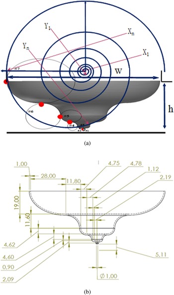
Referring to [Reference Zhao, Chen and Volakis4], one can derive the multi-ellipse geometry (Fig. 1(a)). In the following we take from this reference the main elements related to the antenna profile construction.
The geometry of the proposed antenna. (a) Antenna structure. (b) Dimensions of the antenna (all dimensions are in mm).

The crossings of the x-axis of the spiral, X n, are given by:

where $\emptyset _n$ = π, 3π, 5π, 7π,…..and a is the spiral growth rate.
It is assumed that if the outer surface of the IHA consists of N ellipses.

Each elliptical segment is designed for a frequency sub-band. The combination of these sub-bands constitutes the frequency band targeted in the study. The major radius ratio between adjacent ellipses is constant, involving:

The Nth ellipse (the highest) corresponds to the lowest frequency. Thus, we set w the total width of the proposed antenna and choose XN as w/2. We can then write the spiral rate, a, as follows:

Therefore, the major radius of the other elliptical segments can be determined by inserting (2) into (1).
The growth profile of the outer surface of the IHA provides a control of the input impedance. This is achieved by adjusting the ratio of the major radius Xn to the minor radius Yn of the elliptical segments. In addition, M is a parameter used to adjust the curvature of the convex or concave curve to improve impedance matching [Reference Zhao, Chen and Volakis4].

The indicated factors γi can be expressed by:


It has been shown that the Xn and Yn values must be reduced to satisfy the predefined opening width w and the height h (Fig. 1(a)). Hence, the revised xn and yn become:

The scaling parameters fx and fy are appropriately given by:


Note that the power supply is realized by a coaxial line whose central conductor crosses the ground plane and connects to the first ellipse segment. Thus, the operational upper frequency limit is influenced by the presence of higher order travel modes, while the lower operating frequency of the antenna is a function of its overall size and curvature. In fact, a surface with such a profile ensures that high frequencies are radiated from regions near the power supply and low frequencies from regions far away.
The implementation of this approach proposed in [Reference Zhao, Chen and Volakis4] gives us a starting point for the antenna shaping and sizing that is then optimized with HFSS. On this basis, the influence of the various geometric parameters on the performance of the antenna is studied in order to select the dimensions that offer a good compromise between the desired performance and the size constraints of the antenna. The number of ellipses retained is seven. This choice also takes into account the depth of the void that is allowed to be made in the fuselage of the aircraft.
Among the main specifications required for the antenna fabrication, we can mention:
(1) A 50 Ohm feed coaxial line.
(2) An easy integration of the antenna onto the aircraft fuselage. To that end the monopole is placed in a cylindrical cavity with optimized dimensions (radius and height).
(3) An elimination of the vibration phenomenon in flight as well as to mechanically support the air pressure.
The numbers (1–7) shown in Fig. 1(a) represent the number of the elliptical segments. Considering the optimization study on HFSS, the final dimensions of the IHA structure are given in Fig. 1(b). Initially, the proposed antenna is optimized considering an infinite ground plane. However, although it is a SMA-type feeding, the height above the ground plane comprises seven elliptical curved segments that extend laterally to maintain an inverted-hat profile. All dimensions of the proposed antenna have been optimized while respecting the constraint imposed by the thickness of the fuselage. The antenna made in aluminum is simulated in the range (400 MHz–2 GHz) that includes the DME frequency band (960 MHz–1.22 GHz).
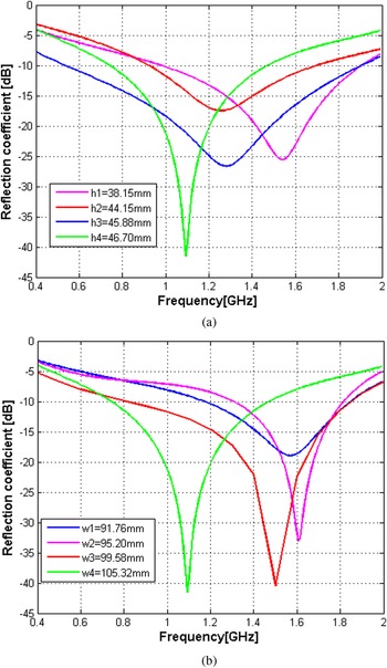
The effects of the antenna height (h: sum of the semi-minor axes of the seven ellipses) and length (w: sum of the semi-major axes of the seven ellipses) on the reflection coefficient are illustrated in Fig. 2. The results clearly show the height and length influence on the resonant frequency and bandwidth of the antenna. For h lower than 46 mm and w lower than 105 mm, the amplitude of the reflection coefficient is reduced and the operating frequency of the antenna is higher than the upper limit of the frequency band targeted. This is mainly due to the small dimension of the IHA that affects its electrical length.
Effects of antenna parameters. (a) Antenna height influence (with w = 105.32 mm). (b) Antenna length influence (with h = 46.70 mm).

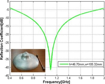
This parametric study allows us to select the best couple (h = 46.70 mm, w/2 = 52.66 mm) for the antenna fabrication. The reflection coefficient simulated for this combination is plotted in Fig. 3. The expected antenna bandwidth (reflection coefficient lower than −10 dB) is 730 MHz (from 0.75 to 1.48 GHz).
Simulated reflection coefficient for the seven-ellipse inverted-hat antenna.

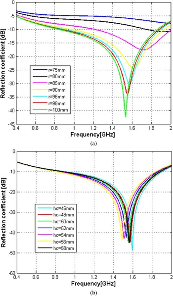
In order to protect the antenna onto the aircraft fuselage, it is encapsulated in a cylindrical empty cavity. After determining the dimensions of the IHA, the volume of the cavity is optimized to minimize the total volume of the antenna while keeping the good matching of the antenna system. The effects of the empty cavity on the antenna performance are presented thereafter. First the height (hc) and the radius (r) of the empty cavity are examined. We give in Fig. 4 the reflection coefficients obtained when hc and r are varied. As can be seen the couple of values that give the best results are hc = 50 mm and r = 100 mm. So, altogether the values for the IHA are h = 46.70 mm, w = 105.32 mm, hc = 50 mm, and r = 100 mm.
Effect of the cavity parameters on the reflection coefficient. (a) Cavity radius influence (with hc = 50 mm). (b) Cavity height influence (with r = 100 mm).

The −10 dB bandwidth extends from 0.80 to 1.84 GHz with a minimum for the reflection coefficients of −43 dB at the frequency of 1.55 GHz. From this simulation analysis, we see that it is possible to obtain a structure whose dimensions are optimized to meet the requirements of radio navigation applications. In order to shift the reflection coefficient response toward low frequencies to cover the DME frequency band and to eliminate the phenomenon of vibration in mid-flight as well as to mechanically support the air pressure, we fill the cavity with different dielectric materials. The materials chosen (low permittivity and loss tangent) are polystyrene, Teflon, and ABS plastic.
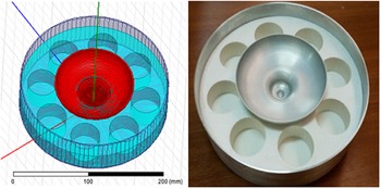
As shown in Fig. 5, the shifted reflection coefficient responses are relatively comparable for the three materials tested. The distortion at higher frequencies (1.4–1.6 GHz) is due to higher order resonance modes of the cavity. Due to its rigidity, compared to Teflon and polystyrene, we choose ABS plastic as the cavity filling material. It also has a better resistance to shocks than polystyrene and a low weight compared to Teflon. In fact, to reduce the weight of the IHA (46% lower), symmetrical cylinders were cut into the ABS plastic while the antenna characteristics remained unchanged (Fig. 6).
Effect of dielectric filling materials on the antenna reflection coefficient.

Simulated and fabricated antenna.

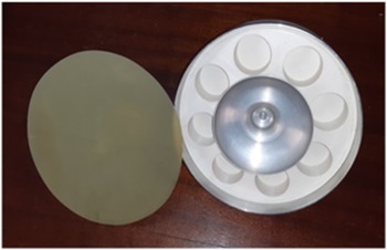
Finally, the cavity is closed with a layer to protect and isolate it from environmental conditions that can generate corrosion (Fig. 7). The material chosen for this layer is epoxy that is very mechanically resistant and has a high electrical resistivity. It is widely used in the aeronautics industry.
Fabrication of the final inverted-hat antenna.

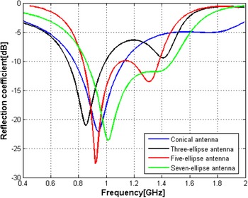
We would like to point out that the choice of the configuration (seven ellipses) was decided after an extensive simulation study, taking care to maintain a good compromise between the complexity and performance of the structure. In fact, four cases were considered, a conical antenna, a three-ellipses antenna, a five-ellipses antenna, and finally a seven-ellipses antenna. We give in Fig. 8 the reflection coefficient obtained for the four cases.
Reflection coefficient for different antenna configurations (conical, three-ellipses, five-ellipses, and seven-ellipses antennas).

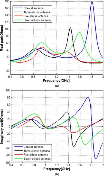
One can note that in case of the conical antenna and three-ellipses antennas (all antennas have the same height and width as the seven-ellipses antenna) the frequency bandwidth does not cover the operating band of the radio navigation system (DME). The coverage of the five ellipses is better, but still a little too just. The number of ellipses mainly influences the real and the imaginary part of the input impedance of the antenna. Indeed, Fig. 9 shows that the increase of the external surface allows changing the nature of the input impedance of the antenna. This parameter impacts the antenna matching.
Performance comparison between the different antenna configurations (conical, three-ellipses, five-ellipses, and seven-ellipses antennas). (a) Real part of input impedance and (b) imaginary part of input impedance (all antennas with same height and width).

As one can see the five and seven-ellipses antennas return practically the same result in terms of input impedance imaginary part but the seven-ellipses antenna offers an input impedance real part closer to 50 Ohms. Therefore, the seven-ellipses configuration has been selected.
Antenna characterization
In order to validate the design and the simulation results, the proposed IHA has been fabricated and experimentally characterized.
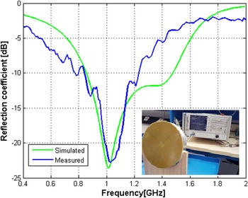
A Rohde & Schwarz-type ZVL vector network analyzer is used to carry out the reflection coefficient measurements of the proposed IHA. Figure 10 shows the test bench and the simulated and measured reflection coefficient parameters. The antenna shows a −10 dB measured bandwidth extending from 0.84 to 1.21 GHz (simulated and measured bandwidth, respectively, of 57.27 and 33.63%) and a minimum reflection coefficient of −22.5 dB at the frequency of 1.02 GHz.
Simulated and measured reflection coefficient for the proposed inverted-hat antenna.

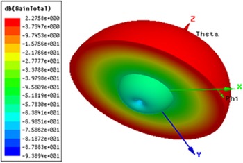
More generally speaking, the simulated and measured reflection coefficient values are in a quite good agreement. The discrepancy may be due to fabrication tolerances caused by the precision of the used three-axis digital lathe, the surface roughness of the antenna and cavity, and the SMA connector not taking into account in the simulation. Given the good results obtained, we have therefore verified the radiation properties of this IHA proposal. The radiation diagram in 3D and polar coordinates, following the two planes (E and H) containing the antenna, shows the existence of a directional lobe with a section at θ = 0° in vertical profile and an omnidirectional radiation in horizontal profile for the simulated frequency (Fig. 11).
Simulated 3D radiation pattern at 1 GHz.

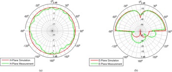
The radiation patterns of the principal planes (E and H) were measured by means of Lab-Volt Series by Festo Didactic, the Antenna Training and Measuring System (ATMS)-model 8092, using a standard Yagi antenna functioning at 1 GHz. The simulated and measured radiation patterns in the H- and E-plane are shown in Figs 12(a) and 12(b), respectively. These radiation patterns exhibit very good results in the E- and H-plane with a difference between simulated and measured results less than 0.5 dB.
Simulated and measured E- and H-plane co-polarization radiation patterns of the antenna at 1 GHz. (a) H-plane results, (b) E-plane results.

The radiation patterns are symmetrical because the ellipse has a symmetrical shape around the z-axis. The perturbations are mainly due to the fact that the distribution of the surface currents depends on the distance between the IHA and the ground plane. It can also be observed that the proposed antenna has an omnidirectional radiation pattern in the H-plane and a vertical polarization. The differences between simulation and measurement data at some angles are partly due to manufacturing tolerances. The small ripples in the radiation patterns measured are mainly caused by the precision of the antenna training and measuring system. The measured gain is 2.2 dB for the lowest frequency band. The maximum difference between the simulated and measured gain is 0.5 dB. In Table 1 the results obtained are compared to those of antennas of relatively similar design.
Comparison of the performance of the proposed antenna with previously published antennas

First, one can note that the antenna proposed in [Reference Zhao, Chen and Volakis4] does not cover the DME bandwidth. Then, among all antennas, the one proposed exhibits the smallest size. Finally, although its radome diameter is smaller than that of other antennas, the proposed antenna demonstrates good overall performance in terms of gain, omnidirectional radiation, and low profile, which are the main concerns of radio navigation systems.
Conclusion
The proposed IHA was designed and verified in the DME band (962–1213 MHz). A reasonable agreement between the measured and simulated reflection coefficients is achieved, with measured reflection coefficients better than −10 dB over the entire DME frequency band. Simulation and measurement results demonstrate that the proposed antenna has good omnidirectional radiation characteristics in H-plane and a vertical polarization. The overall results validate that the proposed antenna can be ideally mounted onto an aircraft for communication or radio navigation systems. This seven-ellipses antenna offers a quite large bandwidth and reduced dimensions, compared to conventional solutions, making it less bulky and easier to be integrated in systems where compactness is an important factor. The antenna is protected by a radome that is made of epoxy material and is transparent to electromagnetic radiation. In addition, the proposed IHA is conceived to be able to bear aero-dynamical loads that cause vibrations and deformations of the antenna. It is an attractive solution for DME.
Conflict of interest
None.
 Z. Hamouda was born in Jijel, Algeria in 1980. He received his engineering degree in aeronautic installation and the M.S. degree in aeronautic from the Blida University, Algeria, in 2006 and 2011, respectively. He received the Ph.D. degree in aeronautics sciences in collaboration between the Institute of Aeronautics and Space Studies, Blida 1 University and the Institute of Electronics, Microelectronics and Nanotechnology (IEMN) University of Lille1 in 2016. His research interest includes the development of organic antenna, wearable antenna, flexible substrate, conductive polymer and aircraft antennas. He served as a reviewer for many international journals and conferences.
 S. Azaizia was born in Guelma, Algeria in 1983. He received his engineering degree in telecommunication from the Military Polytechnic School Algeria in 2006 and the Master degree in microwave and optoelectronics from Paul Sabatier University, Toulouse, France in 2012. She received the Ph.D. degree in photonics and optoelectronics systems from National Institute of Applied Sciences of Toulouse, France in 2018. Her research interest includes the development optoelectronics materials, photonics systems, microstrip antennas and aircraft antennas.
 M. Hideche was born in Tipaza, Algeria in 1994. He received his license and Master degree in aeronautic avionics from the Higher School of Aeronautical Techniques, Algeria, in 2017 and 2020, respectively. His research interest includes the development of microstrip antennas and aircraft antennas.
 A. Zemmam was born in Biskra, Algeria in 1992. He received his license and Master degree in aeronautic avionics from the Higher School of Aeronautical Techniques, Algeria, in 2015 and 2018, respectively. His research interest includes the development of microstrip antennas and aircraft antennas.
 T. Lasri is currently Professor of electronics and electrical engineering in the University of Lille. His main research interests, in the Institut d'Electronique, de Microélectronique et de Nanotechnologie (IEMN), encompass the development of measurement techniques, and the conception and realization of systems for microwave and millimeter wave non-destructive evaluation (NDE) purposes including the characterization of nano-devices. A particular effort has been done toward the microwave qualification of different kind of materials. His research contributions cover also the development of antennas. Another interest is in the area of energy with the development of micro-generators based on thermoelectric transduction. He is author or co-author of about 150 publications and communications. He is head of the Microtechnology and Instrumentation for Thermal and Electromagnetic Characterization (MITEC) research group at IEMN. He is a TPC member for international conferences and is currently on the editorial board of Sensing and Imaging – An International Journal.