I. INTRODUCTION
In recent years, much effort has been devoted to the development of radio frequency identification (RFID) techniques, since RFID systems have found a wide range of applications in many fields. Several frequency bands have been assigned to RFID applications: 125 kHz [Reference Zhang and Lv1], 13.56 MHz [Reference Nummela, Ukkonen, Sydanheimo and Kivikoski2], 433 MHz [Reference Rhyu, Heo, Chung, Harackiewicz and Lee3], 860–960 MHz [Reference Lin, Chen, Chu and Pan4], 2.45 (2.4–2.48) GHz [Reference Mobashsher, Islam and Misran5], and 5.8 (5.725–5.875) GHz [Reference Padhi, Karmakar and Law6]. The advantage of using low frequencies is the low cost involved; however, these systems have short reading ranges with low data transfer rates. The benefit of using high frequencies is that long ranges with high data transfer rates are achievable. The frequencies used by RFID systems vary among different countries, and, in addition, different applications demand different frequencies for operation. Therefore, designing an antenna that operates in three bands should allow the incorporation of various applications into a single antenna. For handheld applications, a wide variety of reader antennas have been proposed [Reference Lin, Chen, Chu and Pan4–Reference Islam, Mobashsher and Misran17]. Some operate in only one frequency band [Reference Lin, Chen, Chu and Pan4, Reference Bao and Ammann7–Reference Hua and Ma9], but antennas have been designed for use with two bands [Reference Mobashsher, Islam and Misran5, Reference Padhi, Karmakar and Law6, Reference Azarbar and Mashhadi10, Reference Shin, Park, Seong and Choi11], and antennas covering three frequency bands have also been described [Reference Lv, Liu and Long12–Reference Islam, Mobashsher and Misran17]. However, only two of the three operating frequency bands in the antennas in [Reference Lv, Liu and Long12, Reference Zhou, Luo, You and Yan13] are RFID bands: 902–928 MHz and 2.4 GHz. The tri-band antennas in [Reference Hong, Behdad and Sarabandi14, Reference Ko and Kim15] work at 433 MHz, 902–928 MHz, and 2.4 GHz, which are not in the bands of interest here. Antennas operating at 902–928 MHz, 2.4 GHz, and 5.8 GHz have been reported [Reference Biakowski, Razali and Boldaji16, Reference Islam, Mobashsher and Misran17], but the antenna in [Reference Biakowski, Razali and Boldaji16] has a low return loss of 6 dB in the 860–960 MHz band, while the antenna in [Reference Islam, Mobashsher and Misran17] has a large size of 80 × 80 × 1.6 mm3, which is almost three times the volume of the antenna proposed here.
In this paper, a new type of tri-band RFID reader antenna is presented. The proposed design allows a reduction in the thickness of the antenna by using a microstrip patch structure that has a single layer. This also makes the manufacturing process less complex. The feedline is on the same side as the simple radiating patch. To meet the requirements for a compact device, the proposed antenna has dimensions of just 115.5 × 20 × 1.6 mm3, while still achieving wide-band performance and high gain in three RFID bands.
The remainder of this paper is organized as follows. Section II describes the principle of the proposed antenna and its detailed design. The effects on impedance matching of variations in the length of the ground and the length and width of the feedline are analyzed in Section III. The measured return loss, peak gain, and radiation pattern of the antenna are presented in Section IV. Section V gives the conclusions of this study.
II. ANTENNA CONFIGURATION
The design of the proposed antenna is an extension of that of the dual-band monopole antenna [Reference Chang and Jiang18]. The radiation portion of the antenna in [Reference Chang and Jiang18] is modified to change the current path and thereby improve the resonance of the antenna. The modified radiation portion of the proposed antenna consists of two parts, one of which is a bent monopole-like arm and the other a rectangular stub. Without the stub, the radiate antenna would resonate at a lower frequency, but the stub introduces higher-frequency resonant behavior. The stub causes the current to concentrate at the end of the bent monopole and thus acts as a capacitive element to couple with the bent monopole, leading to the higher-frequency resonance. The microstrip line feeding the radiation antenna is bent to save space and allow integration of the antenna into a portable reader. The width and length of the feedline can be adjusted to compensate the reactance of the feedline and thereby achieve impedance matching and return loss.
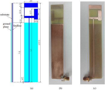
The configuration of the proposed antenna is shown in Fig. 1, together with the design parameters. It is printed on an FR4 substrate of relative permittivity 4.4, thickness 1.6 mm, and area 115.5 × 20 mm2. A ground plane of area 86.8 × 20 mm2 is etched on the bottom side of the substrate, while the radiating antenna is etched on its top side. The optimized width of the feedline W f , length of the feedline L 1, and length of the ground plane L g are 0.5, 93.8, and 86.8 mm, respectively.
(a) Dimensions of the antenna (in mm). (b) Top view of fabricated antenna. (c) Bottom view of fabricated antenna.

The width W f is calculated as follows:
 $$\displaystyle{{W_f} \over h} = \left( {\displaystyle{1 \over 8}e^A - \displaystyle{1 \over {4e^A}}} \right)^{ - 1}, $$
 $$A = \displaystyle{{Z_c \sqrt {2(\varepsilon _r + 1)}} \over {119.9}} + \displaystyle{1 \over 2}\displaystyle{{\varepsilon _r - 1} \over {\varepsilon _r + 1}}\left( {\ln \displaystyle{\pi \over 2} + \displaystyle{1 \over {\varepsilon _r}} \ln \displaystyle{4 \over \pi}} \right),$$
where Z c is the characteristic impedance of the microstrip feedline, ε r is the effective dielectric constant and h is the substrate thickness [Reference Wu, Su, Gan, Chen, Huang and Zhang19]. In this design, h = 1.6 mm.
The calculated value of W f is 3 mm. However, when this value is used, the proposed antenna performs commonly in terms of return loss and peak gain. Consequently, numerical simulations are performed to obtain an optimized antenna with better impedance matching and high gain. The simulations use the high-frequency structure simulator based on a finite-element method. It is known that ground size has a strong effect on antenna performance [Reference Rober, Byndas and Kabacik20–Reference Lee23]. The width of the feedline affects the return loss, while its length determines the size of the antenna. Therefore, these three critical parameters are investigated in the simulations.
II. PARAMETER SIMULATION AND ANALYSIS
The performance of the proposed antenna is determined mainly by the length of the ground plane and the width and length of the feedline. Each physical attribute of the antenna is independently varied, with all other parameters being kept unchanged. For clarity, the final optimized parameters are depicted by the red curve in each simulation figure.
A) Effect of ground plane length
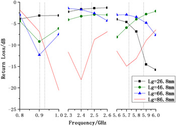
Figure 2 shows the return loss of the antenna for ground planes of different lengths. A −10 dB return loss bandwidth covering the three bands of the RFID is achieved for a ground plane length of 86.8 mm, with longer or shorter ground planes leading to a degradation in the impedance matching of the antenna. It can clearly be seen from Fig 2 that return loss decreases with increasing length of the ground plane at the resonant frequency of 0.9 GHz. Only when the length of the ground plane is 86.8 mm does the antenna resonate at 2.4 GHz. There is a slight frequency shift with decreasing length of the ground plane at the resonant frequency of 5.8 GHz. It is thus demonstrated that variations in ground plane length have a strong effect on the return loss of the antenna.
Return loss for various lengths of ground plane.

B) Effect of feedline length
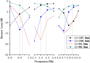
The dependence of the return loss of the antenna on the length of the feedline is shown in Fig. 3. It can be seen that the return loss decreases critically in the 860–960 MHz band at a feedline length of 93.8 mm. In the 2.4–2.48 and 5.725–5.875 GHz bands, only the feedline of length 93.8 mm shows a good return loss, while the resonant frequencies for the other feedline lengths are shifted. The operational bands of the shorter feedline of length 86.8 mm do not cover the bands of interest for the present application, so the antenna cannot be miniaturized further by reducing the feedline length from 93.8 mm.
Return loss for various lengths of feedline.

C) Effect of feedline width
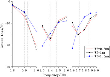
Figure 4 shows the return loss of the antenna versus the width of the feedline. It is obvious that the feedline widths of 0.5 and 1 mm give similar return losses in the three bands of the RFID. However, with the feedline of width 0.5 mm has a wider bandwidth than that of width 1 mm. The 1.5 mm wide feedline exhibits slight shifts in resonant frequency in the 2.4 and 5.8 GHz bands. It can be seen that, in contrast to the other two parameters, variations in feedline width have only a small effect on the return loss of the proposed antenna.
Return loss for various widths of feedline.

The optimum parameters of the proposed antenna are presented in Table 1.
Optimum parameters of the proposed antenna.

IV. EXPERIMENTAL RESULTS AND DISCUSSION
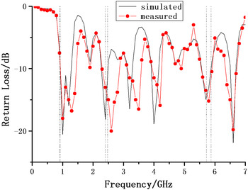
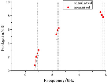
Figures 5 and 6 show both the measured and simulated results for the return loss and peak gain of the proposed antenna. The slight discrepancy between the measured and simulated results may be attributed to fabrication tolerances and numerical limitations in the precise modeling of the antenna and the SMA connector.
Return loss of the optimized antenna.

Gain of the optimized antenna.

Figure 5 shows that the measured bandwidths of the return loss (less than −10 dB) are from 883 MHz to 1.56 GHz, from 2.31 to 2.89 GHz, and from 5.65 to 5.9 GHz, corresponding to bandwidths of 677, 580, and 250 MHz. The measured bandwidth is about twice the simulated one in the 915 MHz and 2.4 GHz bands, while the measured and simulated bandwidths are the same in the 5.8 GHz band.
Figure 6 shows that the measured peak gains of the optimized antenna are 2–2.8, 5.3–5.7, and 7.7–7.2 dBi in the 915 MHz, 2.4 GHz, and 5.8 GHz bands, respectively. The proposed miniature antenna shows high gains with small size in the three RFID bands. The gain variations are observed to be <1 dBi in the three bands, which indicates excellent stability of performance. In practice, high-gain antennas are always preferred, so that the RF output power can be reduced to save battery life under regulated maximum-allowable effective isotropic radiated power. Besides, theoretical calculation has shown that every additional 3 dB of reader gain increases the tag read range by approximately 40%. The simulated gains in the 915 MHz and 5.8 GHz bands are similar to the measured ones, although the simulated gain is lower than the measured one by about 1 dBi in the 2.4 GHz band.
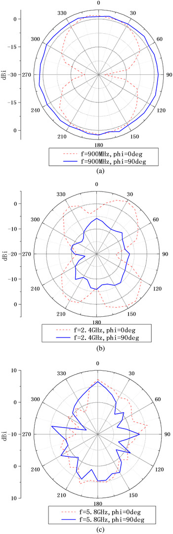
The radiation patterns for the proposed antenna in the x–z (ϕ = 0°) and y–z (ϕ = 90°) planes at 900 MHz, 2.4 GHz, and 5.8 GHz are shown in Fig. 7. The radiation pattern at 900 MHz is omnidirectional, while those at 2.4 and 5.8 GHz are directional with some nulls. The maximum gains in the three bands are in the forward direction, which is important for a portable reader.
Measured radiation patterns of the optimized antenna at RFID frequencies: (a) 900 MHz, (b) 2.4 GHz, and (c) 5.8 GHz.

V. CONCLUSION
In this paper, a miniature tri-band RFID reader antenna has been proposed for portable devices. The antenna has a small profile of just 115.5 × 20 × 1.6 mm3, but it performs over wide bandwidths and with high gain in three bands. The length of the ground plane and the length of the feedline affect the return loss of the antenna dramatically, but the width of the feeedline has a slight effect on the return loss of the antenna. They are optimized to achieve good performance. The measured bandwidths (return loss <−10 dB) of the proposed antenna are 677, 580, and 250 MHz in the three operating bands, 883–1560 MHz, 2.31–2.89 GHz, and 5.65–5.9 GHz, respectively. The measured peak gains of the antenna are 2–2.8, 5.3–5.7, and 7.7–7.2 dBi in the 915 MHz, 2.4 GHz, and 5.8 GHz bands, respectively.
ACKNOWLEDGMENTS
The paper is funded by “Shaanxi Provincial Science and Technology Department (2014K05-29), Shaanxi Provincial Education Department (grant no. 14JF028) and Research Group of Xi'an University of Posts and Telecommunications of New Star (grant no. XYXX2014)”.
 Bo Wang was born on September, 1986, in Xi'an, China. He received the B.S. degree from Xi'an University of Technology, Shaanxi Province, China, in 2008. He received the M.S. and Ph.D. degrees from Xidian University, Shaanxi Province, China. He is a Lecturer in School of Automation, Xi'an University of Posts and Telecommunications. His current research interest is RFID tag, reader antenna design, and measurement.
 Wenqing Wang is currently a Professor and the president of school of Automation, Xi'an University of Posts and Telecommunications, Shaanxi Province, China. His research interests include intelligent information processing and analysis of information systems.