Introduction
Due to the large demand for novel flexible systems such as smart clothes [Reference El Atrash, Abdalla and Elhennawy1], RFIDs, healthcare systems [Reference Chamindra, Kumar, Chakrabartty and Song2–Reference Kaim, Kanaujia, Kumar, Choi, Kim and Rambabu4], and many other applications [Reference Khajeh-Khalili, Shahriari and Haghshenas5, Reference Zahran, Abdalla and Gaafar6], flexible electronics are introduced as a very interesting technology. Flexible antennas are one of the most interesting elements in the whole flexible system. Flexible systems require special materials for designing the various system elements. The most used materials for designing flexible electronics are nanomaterials [Reference Mansor, Rahim and Hashim7], polymers [Reference Bobbili Naga, Palaniswamy, Thipparaju, Nishesh and Molupoju8], and nanocarbon [Reference Abdel Aziz, Abdel-Motagaly, Ibrahim, El Rouby and Abdalla9]. One of the nanocarbon families is expanded graphite (EG). EG is preferred over nanometals like gold, silver, copper, and aluminum conductive inks, especially in terahertz applications. Gold and silver have a high cost than nanocarbon. Aluminum and copper have a relatively low price but they suffer from oxidization with time, which affects the conductivity of the device. Polymers suffer from thermal and mechanical instability. The previous reasons make nanocarbon preferred to be used in the design of future flexible electronics.
Graphene, the 2-D carbon atoms arrangement [Reference Geim and Novoselov10], has been used for various graphene applications, such as tunable components [Reference Abdel Aziz, Ibrahim and Abdalla11], printed components [Reference Leng, Huang, Chang, Chen, Abdalla and Hu12], and many other applications. EG is multiple graphene layers stacked over each other with a very small separation between the graphene layers. By performing a process of mechanical agitation for EG, graphene nanoplatelets (GNP) could be prepared. The process of mechanical agitation can be performed through solvent exfoliation by shearing [Reference Arapov, Rubingh, Abbel, Laven, de With and Friedrich13] or sonication [Reference Huang, Pan and Hu14]. The resulted GNP ink has a high conductivity that makes it suitable for printed circuits. But, the processes performed on the EG to obtain GNP cause defects in the sheet and decrease its lateral size. These reasons decrease the conductivity of the ink. Besides, the required heat treatment for the ink to remove the binders makes GNP not suitable for heat-sensitive substrates as paper. Because of these problems, using EG ink for printed electronics is a superior solution.
Coplanar waveguide (CPW) antenna is one of the most widely used antenna configurations in literature [Reference Ding and Jacob15]. It also can be named slot antenna. Slot antennas have the main advantage of having a wide bandwidth impedance matching [Reference Elhabchi, Srifi and Touahni16, Reference Elhabchi, Srifi and Touahni17]. They were used in the design of multiband antennas as in [Reference Deng and Feng18]. Slot antennas are widely used in the design of circular polarized antennas as in [Reference Saini and Dwari19] and high gain flexible antennas as in [Reference El Atrash, Abdalla and Elhennawy20]. Due to the fabrication restrictions in printed graphene components, slot antennas with a wide bandwidth of impedance are preferred to be used. In this work, CPW fed with a U-shape conductor strip-based CPW monopole antenna is designed at 2.4 GHz for wireless applications. Flexible paper with relative permittivity 3.2 and thickness = 120 μm is used as a substrate. The antenna fabrication steps are discussed. A brief discussion of the preparation process is included. Measurements of the antenna reflection coefficient and pattern analysis are discussed in the next words. To ensure the antenna parameters, the antenna is simulated with two different electromagnetic (EM) solvers, CST and HFSS.
Antenna design
The proposed antenna is designed based on a CPW monopole antenna with a U-shape conductor strip. The antenna structure is mainly composed of a conventional CPW feeding monopole antenna surrounded by U-shape conductor strip ground. EG ink, with a thickness of 30 μm and conductivity of 1 × 10⁴ Sem./Sq., is used as a conductor for the antenna design. Flexible paper, with relative permittivity (ɛr = 3.2), loss tangent 0.0092 [Reference Mandrić Radivojević, Rupčić, Srnović and Benšić21], and thickness of 120 μm, is used as a substrate. On one hand, the conventional CPW monopole antenna is designed to operate at 2.4 GHz applications as shown in Fig. 1(a). The optimized dimensions of this antenna are L 1 = W 1 = 60 mm with patch length LP 1 = 37 mm and width WP 1 = 35 mm. The simulated reflection coefficient is shown in Fig. 2 (black curve). From Fig. 1(a) we can see that the antenna has a large area which increases the overall size of the system. On the other hand, by using the U-shape conductor strip, the antenna length is decreased to 13 mm which reduces the antenna length. The overall antenna length is decreased to 35 mm with the same previous width. By using a U-shape conductor strip CPW antenna, the monopole operating frequency is maintained at 2.4 GHz with a smaller area. The simulated S 11 for the two antennas is added in Fig. 2. To ensure the results extracted from CST software, the U-shape conductor strip-based antenna is simulated by using HFSS. The two results are shown in Fig. 2. As shown in Fig. 2, the two antennas resonate at the same frequency (with a narrow band for the case of the proposed antenna). But, the U-shape conductor strip-based antenna has a smaller surface area making it more preferred for printed components. The final proposed antenna shape is illustrated in Fig. 1(b) and its dimensions are tabulated in Table 1. The antenna lumped equivalent circuit is shown in Fig. 1(c), with L and C elements that control the resonant frequency and resistance R that represents the radiation resistance of the antenna [Reference Hamid and Hamid22, Reference Al-Zayed and Shameena23]. The shunt branch of series resistance R2 and inductor L2 controls the input impedance of the antenna.
2-D layout of the two antennas; (a) CPW-fed monopole antenna. (b) The proposed U-shape conductor strip-based antenna. (c) The equivalent circuit model of the CPW antenna.

Comparison between the CPW antenna and U-shape conductor strip antenna based on both CST and HFSS reflection coefficient with the equivalent circuit for monopole antenna.

Dimensions of the proposed antenna (all in mm)

The values of the lumped elements are R 1 = 45.55 Ω, R 2 = 11 Ω, L 1 = 0.456 nH, L 2 = 1.35 nH, and C 1 = 10.1 pF. Because of the fabrication limitations, the CPW feeding line has a 3.5 mm width and 0.5 mm gap. These values shift the input impedance of the CPW feeding line from exactly 50 Ω. As it is known from the CPW feeding configuration, the gap width between the feeding line and two grounded stubs affects the feeding input impedance.
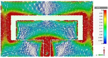
As it is known, the U-shape conductor strip increases the path of the surface current of the antenna which produces a higher gain value of the antenna than the conventional CPW antenna. This explanation is ensured by the current distribution shown in Fig. 3. The surface current shows that, at the resonant frequency (2.4 GHz), the surface current distribution of the antenna is concentrated at U-shape conductor strip sides of the ground, beside the radiating element itself.
The surface current distribution of the U-shape conductor strip-based antenna at the resonant frequency (2.4 GHz).

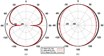
To ensure the superiority of the proposed antenna, the normalized E-plane and H-plane radiation patterns for the two antennas are compared in Figs 4(a) and 4(b), respectively. As shown, the U-shape conductor strip-based antenna has a narrower beamwidth in H-plane compared to the traditional CPW monopole. Hence, the U-shape conductor strip-based antenna is more directive than the conventional antenna.
Comparison between the simulated polar plot of conventional antenna and the proposed one. (a) E-plane, and (b) H-plane.

Graphene preparations and analysis
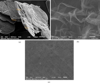
Expandable graphite (EG), Asbury carbon grade 3772, with 300–500 mm lateral size and 10–50 mm thickness is used as initial material as shown in Fig. 5(a). EG is initially inserted between two tables and subjected to a compression of 50 bar. Then, it is placed inside a rounded flask and evacuated. To expand the graphite, the flask is subjected to microwave radiation with 900 watts. Repeating this process two times for 30 s resulted in an expansion of graphite layers to 2–10 mm with an increase of 200 times. The EG is washed by using distilled water, and then the obtained ink is dried at 100°C. The obtained EG is shown in Fig. 5(b). To use the ink as a dry ink for the printed antennas, the residual acidity removal process is performed by a repeated water washing process. The pH of the water used for washing is increased from 2 to 7 [Reference Chung24]. The obtained EG has binder-free compact and flexible sheets. EG is then compressed, resulting to obtain a compressed EG with low surface roughness in the surface plane as shown in Fig. 5(c). As shown in Fig. 5(c), the obtained compressed EG has worms which when it is increased, the ability of the sheet for radiating EM waves is increased [Reference Hong and Chung25].
(a) EG flakes, (b) EG, (c) EG after compression.

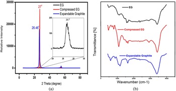
Different analyses for the three stages, EG, and compressed EG are performed as in [Reference He, Lin, Chen, Cao, Lin and Du26]. The X-ray powder diffraction (XRD) analysis is shown in Fig. 6(a). Concerning the diffraction peak (002) pattern, the angle of the peak, and the interlayer d-spacing, a comparison between the three studied states has been concluded in Table 2. From the results, it can be found that the EG diffraction peak dropped and came to border than the EG. This is a result of microwave treatment. Also, a significant decrease in the stacked layers of numbers is achieved. These obtained results agree with the results in [Reference He, Lin, Chen, Cao, Lin and Du26]. A sharp and strong diffraction peak is obtained by compressing EG [Reference Abdel Aziz, Abdel-Motagaly, Ibrahim, El Rouby and Abdalla9, Reference He, Lin, Chen, Cao, Lin and Du26]. By completing the analysis of the material, the Fourier-Transform Infrared spectroscopy (FTIR) technique is used and the results are shown in Fig. 6(b).
Different analysis results of the expandable graphite, EG, and compressed EG. (a) XRD patterns. (b) FTIR spectra.

XDR analysis for expandable graphite, EG, and compressed EG

It is noticed that the absorption peaks for the three cases ranged from 3300 to 3600/cm. These results correspond to the stretching vibration of the −OH group for the three cases. Noticing clear signals at 1640 and 1580/cm means a C = C double bond stretching vibration [Reference Salvatore, Carotenuto, De Nicola, Camerlingo, Ambrogi and Carfagna27] and C–C skeletal vibration [Reference Cong, Long, Cui, Li, Dong, Yuan and Zhang28], respectively. The absence of peaks at 1740–1720 and 1230/cm related to C = O, and C–O, respectively, indicates little defects of the graphitic basal plane [Reference Kim, Kuila and Lee29] resulted from the microwave thermal expansion.
Antenna fabrication, measurements, and analysis
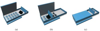
The antenna is fabricated by using the previously prepared ink. The fabrication process steps are illustrated in Fig. 7 (for simple antenna pattern). First, the antenna pattern is cut in a 2.5 mm acrylic sheet to achieve the negative shape. Then the pattern is placed over the paper (used as a flexible substrate). EG powder is used to fill the pattern area. The acrylic punch is used to compress the EG. The final compressed EG sheet thickness has an average thickness of 30 μm [Reference Abdel Aziz, Abdel-Motagaly, Ibrahim, El Rouby and Abdalla9]. Also, the electrical conductivity was measured and equaled 1 × 10⁴ Sem./Sq. To measure the RF antenna parameter, like the antenna reflection coefficient, SMA must be connected to the paper-based EG antenna. The Silver conductive epoxy (MG Chemicals 8330S) is used in the soldering process.
The antenna printing steps configurations. (a) Antenna pattern design, (b) antenna pattern filled with EG, (c) compression of EG.

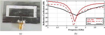
The final fabricated antenna is shown in Fig. 8(a). Then, the antenna reflection coefficient is measured by using vector network analyzer with the results shown in Fig. 8(b). The measured results indicate good results with an acceptable agreement with the simulated one. HFSS simulation results are added to the comparison as a second check to validate the S-parameters performance. The measured result has the same trend as the simulated results; however, there are differences between the measured and simulated results. These are because of the fabrication process, SMA soldering, and the very thin paper substrate, which affect the measuring process.
(a) The fabricated reflector antenna. (b) Measured antenna reflection coefficient.

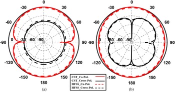
The antenna radiation patterns for gain and the efficiency are not measured because of the lack of the measurements of the proposed antenna. Instead, comparisons between simulation results for antenna from CST and HFSS EM solvers have been achieved. The simulated co-polarized and cross-polarized radiation patterns for the two software results in both the E-plane and H-plane are shown in Figs 9(a) and 9(b), respectively. As shown, the proposed antenna radiation pattern has a very good result in the E-plane as shown in Fig. 9(a) with a level difference lower than −55 dB for CST simulation results. HFSS results have the same response but with little degradation. For the H-plane, as shown in Fig. 9(b), the antenna performance is approximately the same.
Comparison between simulated co-polarized and cross-polarized radiation patterns for the two planes resulting from CST and HFSS. (a) E-plane. (b) H-plane.

A comparison between the two antennas (without and with a U-shape conductor strip) is shown in Fig. 10. As shown, in the case of the conventional antenna, the antenna simulated gain has 1.7 dBi and the simulated efficiency is below 80% at 2.4 GHz, while for U-shape conductor strip-based antenna, the simulated gain is around 4 and 3.5 dBi, and the simulated efficiency are higher than 90 and 85% at 2.4 GHz for both CST and HFSS, respectively. It is worth commenting that the efficiency value may be smaller than reported simulation values on real measurements due to the losses in the graphene at microwave frequencies.
Comparison between simulated gain/efficiency (gain in black color and efficiency in red color) for without and with U-shape conductor strip-based antenna resulting from CST and HFSS.

The bending effect on the antenna reflection coefficient is studied as shown in Fig. 11. The proposed antenna is curved around the cylindrical material shape with different radius values R as shown in Fig. 11. The radius of the cylindrical shape is changed from R = 10 mm to R = 30 mm. The simulated results of the antenna under different bending radius values are illustrated in Fig. 11. The antenna has good matching with a reflection coefficient lower than −10 dB for bending radius till 10 mm. The results ensure that the proposed antenna introduced good performance by changing the bending radius values.
The antenna reflection coefficient under different bending radius values.

A comparison between the proposed antenna and similar recent works is discussed in Table 3. As shown in Table 3, the proposed work conductivity is compared with [Reference Leng, Pan, Jiang, Hu, Ouslimani and Abdalla30–Reference Ram and Singh33]. Also, the antenna gain is superior compared to the antenna size. As it is clear, the antenna has a high simulated gain value with good conductivity. Also, this simulated value may be less on real measurements due to losses in the graphene at microwave frequencies.
Comparison between the proposed work and the recent similar works

Conclusion
EG, single band, U-shape conductor strip-based monopole antenna for 2.4 GHz wireless applications has been discussed. Flexible paper with a relative permittivity of 3.2 and a thickness of 120 μm is used as a substrate to make the antenna valid to be used for flexible applications. The antenna design steps have been included, with a discussion for the material preparation, antenna fabrication, and measurements. The antenna has 4 dBi simulated gain and above 90% simulated efficiency at 2.4 GHz. The antenna-obtained results indicate its superiority for use in wireless systems.
 Ahmed A. Abdel Aziz received the B.Sc. degree, with grade of excellent with honors, in electrical engineering from the Avionic Engineering Department, Military Technical College, Cairo, Egypt in 2014. He is currently pursuing the M.S. degree in Graphene-Based Metamaterial Microwave Components/Antenna from Military Technical College. From 2014 to 2016, he was a Research Assistant with AF Research Center in design of microwave communication systems. His research interest includes microwave components, antennas, metamaterial structures, and graphene RF applications.
 Ali T. Abdel-Motagali received his bachelor degree from the Faculty of Pharmacy, Ain-Shams University (2011). He joined the Faculty of Postgraduate Studies for Advanced Science in 2013 and received his master degree in material science and nanotechnology in 2018. Then, he had Erusmus plus mobility program to Jean University in Spain for 6 months. He also got internship at Institut de Chimie Moléculaire et des Matériaux d'Orsay, University of Paris Saclay, France for 6 months. His main research is focus in material science, nanotechnology, and water electrolysis.
 Ahmed A. Ibrahim was born in 1986. He received the B.Sc., M.Sc., and Ph.D. degrees in electrical engineering from the Electronic and Communication Engineering Department, Minia University, Elminia, Egypt in 2007, 2011, and 2014, respectively. He is now an Associated Professor in Electrical Engineering Department in the Faculty of Engineering Minia University. He has been a Visiting Professor in University Pierre and Marie Curie, Sorbonne University, Paris VI, France for 7 months and Otto-von-Guericke-Universität Magdeburg-Germany for 6 months. He has published more than 81 peer-reviewed journals and conference papers. His research has focused on miniaturized multiband antennas/wideband and microwave/millimeter components. Also his research includes MIMO antennas and energy harvesting systems. Dr. Ahmed A Ibrahim is a member of the IEEE and senior member in URSI. He is also a member in the national committee of radio science in Egypt. He is currently a reviewer in IEEE Antennas and Wireless Propagation Letters, IEEE Microwave Wireless Components, IEEE Access, IET Microwave, Antenna and Propagation, IET Electronics Letters, MOTL, and many others journal and conferences.
 Waleed M. A. El Rouby earned his M.Sc. and Ph.D. degrees from Beni-Suef University, Egypt in May 2008 and November 2011, respectively. In September 2013, he worked as an Assistant Professor at Beni-Suef University, Egypt. In September 2015, he got Erasmus Munds postdoctoral fellowship at Physical Chemistry Department, Faculty of Chemistry, Universidade de Vigo, Spain. In December 2017, he got a postdoctoral position for 2 years at Institut de Chimie Moléculaire et des Matériaux d'Orsay (ICMMO), Recherche et Innovation en Electrochimie pour l'Energie, Université Paris-Sud, France. Now, he is an Associate Professor of materials science and nanotechnology at the Faculty of Postgraduate Studies for Advanced Sciences, Beni-Suef University, Egypt. His research work is focusing on the elaboration of different morphological nanomaterials with high surface area for different purposes such as water splitting, methanol electrooxidation, water treatment, photocatalysis, and sensing applications.
 Dr. Mahmoud A. Abdalla was born in 1973. He received the B.Sc. degree, with grade of excellent with honors, and M.Sc. degree in electrical engineering from the Electrical Engineering Department, Military Technical College, Cairo, Egypt in 1995 and 2000. He was awarded the Ph.D. degree from the School of Electrical Engineering, Manchester University, UK, in 2009. He has been with Military Technical College since 1996 where he is an Associated Professor and Head of Electromagnetic Waves Group. He is a Visiting Professor in the Department of Computer and Electrical Engineering, University of Waterloo, Canada since 2017. Dr. Mahmoud was the recipient of Egyptian encouragement state prize for engineering sciences in 2014. He has published more than 200 peer-reviewed journal and conference papers. His research has focused on miniaturized multiband antennas/wideband and microwave/millimeter components. Also his research includes MIMO antennas and energy harvesting systems. Dr. Mahmoud Abdalla is a senior member of the IEEE and the European Microwave Association EuMA. He is currently a reviewer in Scientific Reports, IEEE Transaction on Antenna and Propagation, IEEE Antennas and Wireless Propagation Letters, IEEE in Microwave and Theory Techniques, IEEE Microwave Wireless Components, IEEE Transaction in Magnetics, IEEE Transaction on Plasma Science, IET Microwave, Antenna and Propagation, IET Electronics Letters, IET Communications, and many others.