Introduction
Biotribology is an integrative research with an aim to assess biological structures and scrutinize their role and characteristics, which eventually focus on improving the aspect and durability of human life [Reference Katta, Jin, Ingham and Fisher1]. In reconstructive orthopedic surgeries, metals and their alloys have significantly played a preponderant role as constitutional biomaterials [Reference Straley, Foo and Heilshorn2]. Metals such as stainless steel, magnesium, titanium, and chromium–cobalt are routinely used as implant materials [Reference Bose, Banerjee and Bandyopadhyay3]. However, orthopedic doctors and engineers have been continually scuffling for deterrence of early failure of the artificial knee and hip implants. The biomedical science community claimed that the service life of biomaterial implants in the human body has reduced from 30 years to approximately 10–12 years [Reference Thrivikraman, Madras and Basu4]. The duration of the metallic implant is evaluated by its toxic nature and abrasion and wear behavior [Reference Hussein, Mohammed and Al-Aqeeli5]. Therefore, cytotoxicity, corrosion resistance, and wear resistance are the major considerable aspect to be taken care of to produce a further efficient joint. Wear failure may occur due to the release of incompatible metal ions or wear debris in the bone–implant interface [Reference Sahasrabudhe6, Reference Eremina and Smolin7]. Among the metals and alloys, cobalt–chromium (Co–Cr) alloys provide the best services in the domain of biomaterials for the last 50 years. The Co–Cr alloys, such as F75 (Co–Cr–Mo), F90 (Co–Cr–W–Ni), and F562 (Co–Ni–Cr–Mo), are extensively utilized in dental amalgam and orthopedic and cardiac applications owing to their outstanding mechanical properties, biocompatibility, and superior corrosion and wear resistance [Reference Mantrala, Das, Balla, Rao and Rao8, Reference Tarzia, Bottio, Testolin and Gerosa9]. Beake and Liskiewicz examined the wear characteristics of Ti6Al4V, 316L stainless steel alloys, and Co–Cr alloys and affirmed that the Co–Cr alloy possesses improved wear resistance compared with other materials [Reference Beake and Liskiewicz10]. Similarly, Niinomi concluded in his research that the preponderance of hip joints had been constructed from Co–Cr alloys due to their high strength, ductility, and superior wear and corrosion resistance [Reference Niinomi11]. Chiba et al. reported that the wear behavior of material had been significantly affected by the selection of the metal forming process. The results of their study demonstrated that the forged Co–Cr–Mo alloy exhibited higher wear resistance than the cast Co alloy with a large amount of carbon content [Reference Chiba, Kumagai, Nomura and Miyakawa12]. Likewise, Wang and Liang considered the liquid zinc solution to scrutinize the Co–Cr–W alloy’s corrosive wear performance. The results of their study revealed that alloy’s eutectic phase and the increase in the temperature of liquid zinc solution damaged the alloy surface [Reference Wang and Liang13]. Bose et al. [Reference Bose, Ke, Sahasrabudhe and Bandyopadhyay14] discussed the additive manufacturing (AM) methods and their applications for surface modification of biomaterials. Their study on Co-based materials confirms the enhancement of wear and abrasion resistance by employing AM techniques. The work published by Cetiner et al. described that the fabrication of Co–Cr alloy by TiO2 layer enhanced its bioactivity and wear resistance [Reference Cetiner, Paksoy, Tazegul, Baydogan, Guleryuz, Cimenoglu and Atar15]. Moreover, Sahasrabudhe et al. [Reference Sahasrabudhe, Bose and Bandyopadhyay16] utilized the Laser Engineered Net Shaping (LENS™) process intended for reinforcing the Co–Cr–Mo alloy by calcium phosphate (CaP). They observed that CaP added alloy exhibits improved wear resistance and minimized emission of metal ions.
To enhance the wear and corrosion resistance and the biocompatibility of bioimplant, Mahajan and Sidhu elucidated the novel surface modification treatment, namely, electrical discharge machining (EDM) [Reference Mahajan and Sidhu17]. In their recent research, they modified the Co–Cr alloy surface by electric discharge treatment (EDT) and observed that the treated samples show improved corrosion resistance and hemocompatibility [Reference Mahajan and Sidhu18]. Similarly, Bhui et al. also discussed the merits of EDM in the field of biomaterials surface treatment and reported that EDM promotes the bioactivity and wear and corrosion resistance of Ti alloy implants for orthopedic purposes [Reference Bhui, Singh, Sidhu and Bains19]. Recently Li et al. also confirmed that the surface modification by powder mixed electrical discharge machining (PMEDM) is the most promising approach to ameliorate the bioactivity, wear performance, and corrosion resistance of bioimplant for superior osseointegration surface [Reference Li, Zhao, Li, Feng and Bai20].
Therefore, in this study, electrical discharge treated Co–Cr implant alloys is analyzed for their tribological performance. Herein, the wear characteristics such as wear rate and coefficient of friction of the machined and unmachined substrates are examined on the pin-on-disc tribometer in the presence of biological (Ringer) solution. Moreover, in vitro cytotoxicity test was also performed on the substrates for confirming the biocompatibility of the samples.
Results
The experimentation was conducted on Co–Cr alloy substrates at different spark energy levels. The cell culture study was performed on the substrates for analyzing the in vitro cytotoxicity. The tribological behavior of the substrates was examined in a biological-like environment.
Cytocompatibility analysis
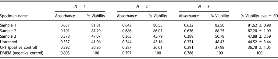
The cytotoxicity of untreated and EDT samples was calculated by evaluating the % MG63 cell viability. The results demonstrated that the cell viability on a negative control sample (cell grown on coverslip) was observed to be considerably high compared with Co–Cr samples (P < 0.001). However, an insignificant difference in cell viability was observed in sample 3 and untreated specimen compared with the positive control (CPT) (P > 0.05). Sample 1 and Sample 2 exhibited significantly higher cell viability in the range of 80–88% (P < 0.05). The MG63 cell viability of sample 2 was approximately reformed as 1.9 times greater than that of the unmachined sample. The percentage cell viability and absorbance (Abs) value of the machined and untreated samples are presented in Table I. The toxicity responses of cells interacted with samples are shown in Figs. 1(a) and 1(b). Figure 1(a) represents the 24-well plate after MTT assay, where the dark purple color of samples represented a large number of living cells (MG-63) on the substrate. However, the comparison of percentage cell viability on samples is illustrated in Fig. 1(b).
Absorbance and % cell viability of testing samples (where N represents number of attempts of each experiment).

(a) 24-Well plate after MTT assay: dark purple color represents a large number of live cells (MG-63). (b) Comparison of percentage cell viability on samples. All values are expressed as average ± SD (at n = 3).

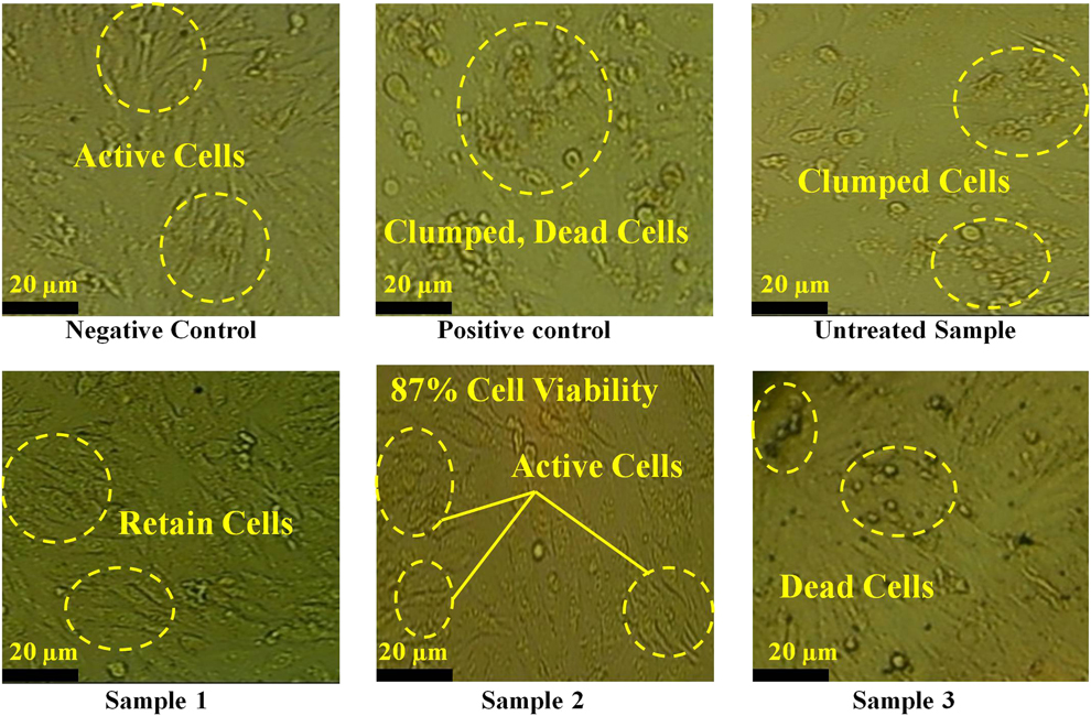
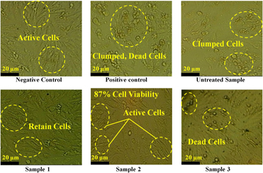
Similar results were also observed in MG-63 cell morphology by microscope images. Figure 2 shows the maximum number of living cells observed on negative control samples. Samples 1 and 2 that show a higher percentage of cell viability also visualized with an enormous number of retained cells. The morphology of the MG-63 cells on these samples was oval to spindle shape, as reported mostly [Reference Pautke, Schieker, Tischer, Kolk, Neth, Mutschler and Milz21]. However, dead or extinct cells were observed on untreated and EDT sample 3. The microscope images of these samples (untreated and sample 3) were alike as a positive control sample. These outcomes, in accordance with % cell viability, are indicative of enhanced biocompatibility of EDT samples compared with the unmachined sample. Sample 3 does not capitulate good results, but the other two machined samples admire the EDT implants in the biomedical field.
Microscope images represent cytotoxicity response on samples. Samples 1 and 2 show large number of retained cells. Dead or extinct cells are observed on untreated sample and EDT sample 3.

Tribological investigation of EDT surfaces
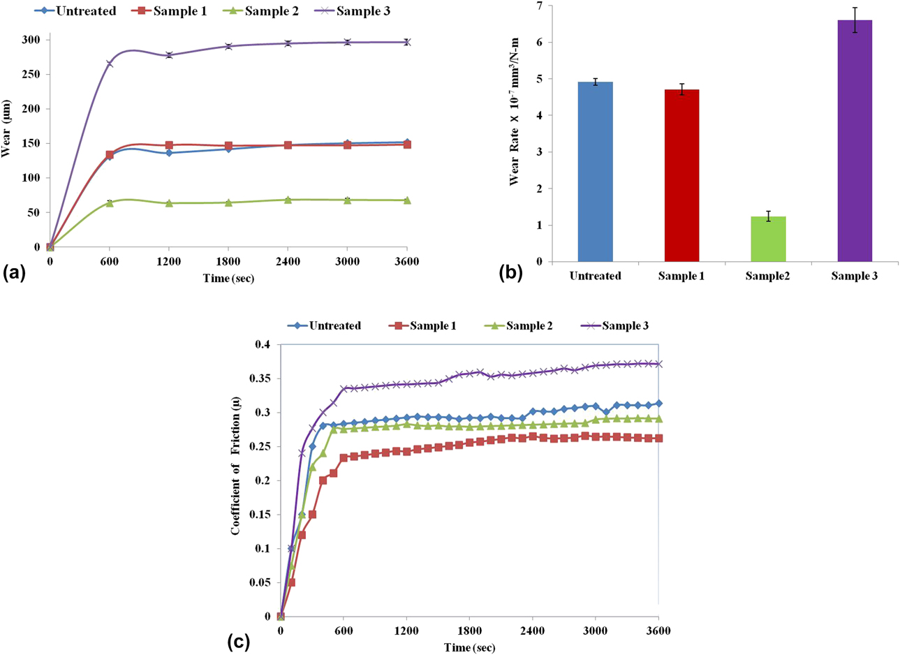
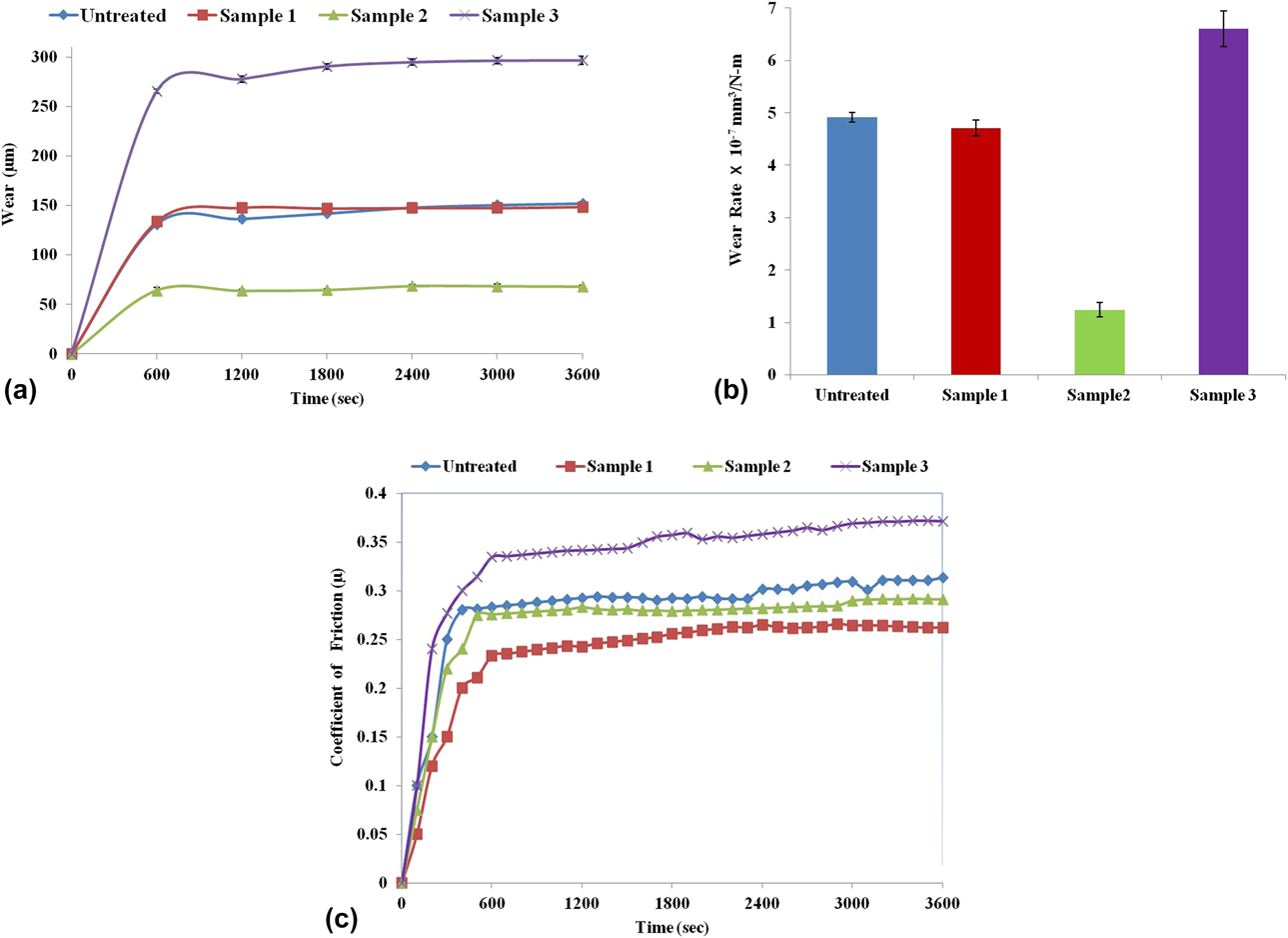
Table II represents the wear rate and coefficient of friction of each specimen. It has been observed that among all the pin samples, the amount of wear rate of sample 3 was highest [(6.6 ± 0.34) × 10−7] mm3/Nm, whereas sample 2 was observed with the lowest value of wear rate [(1.24 ± 0.14) × 10−7] mm3/Nm among all the samples tested on a pin on the disc test rig. The untreated specimen and sample 1 almost exhibited the same wear rate results. Figure 3(a) shows the relation of wear (µs) with time for different samples, and the wear rate of all specimens are compared in Fig. 3(b). Figure 3(c) demonstrates the variation of the coefficient of friction with time for all pin samples. It has been depicted that the value of the coefficient of friction (µ) is highest for sample 3 (µaverage = 0.37) and lowest for sample 1 (µaverage = 0.26). The untreated specimen and sample 2 exhibit almost equivalent value of µ in the very beginning of the tests. With increasing the duration of the experiment, the values of µ for the untreated sample and EDT sample 2 slightly increase from 0.28 to 0.31 and from 0.27 to 0.29, respectively.
Calculated wear rate and coefficient of friction (COF) of samples.

(a) Variation of wear (µm) with a time of pin samples. (b) Wear rate comparison of samples. (c) Variation of the coefficient of friction (µ) with a time of pin samples.
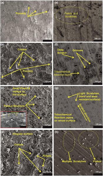
The surface topographies of EDT and untreated substrates (before wear test) are represented in Figs. 4(a)–4(d). The micropores were observed on the as-received substrate (untreated) from Siora Surgicals, New Delhi, India [Fig. 4(a)]. However, the microstructure of EDT sample 1 (5 A current and 60 μs pulse on-time) demonstrated the formation of craters and pores on the surface [Fig. 4(b)]. However, the topography of sample 2 (10 A current and 60 μs pulse on-time) exhibited small peaks, valleys, and micropores on the surface [Fig. 4(c)]. It was owing to the fact that the spark energy frequency and flushing system were effectively synchronized to remove debris from the machining area. Figure 4(i) represents the cross-sectional image of sample 2. A thick recast layer was witnessed on the sample, which was due to the redeposition of melting material from work specimen and electrode during regular sparking in the EDM process. The thick recast layer on the surface enhanced the microhardness and wear resistance of the sample. However increasing the current (up to 16A) generates higher energy of spark, resulting in irregular surface texture, large craters, ridges and resolidified metallic droplets on the surface [Fig. 4(d)].
FESEM images of untreated and treated substrates before (a–d) and after (e–h) wear testing. Before wear testing: (a) untreated substrate shows porous structure; (b, d) sample 1 and sample 3 surfaces demonstrate rough, porous grain with craters; (c) sample 2 surface shows peaks, valleys, and micropores along with suitable recast layer on its cross section (i). After wear testing: (e) untreated substrate demonstrates flakes, delaminations, and small surface scratches; (f) worn surface of sample 1 witnesses tribochemical layers, deep scratches, grooves, and delaminations; (g) sample 2 affirms lesser scratches, no delaminations, and tribochemical oxide layers on the whole surface; (h) sample 3 exhibits multiple scratches and flakes.
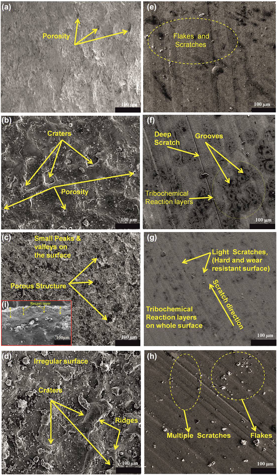
The wear appearances of the EDT and untreated samples after conducting the tribological test are shown by field emission scanning electron microscopy (FESEM) images in Figs. 4(e)–4(h). The untreated surface was observed with flakes, delaminations, and small surface scratches [Fig. 4(e)], whereas modified sample 1 and sample 2 were seen with dark patches. These dark regions represented as a tribochemical reaction (wear of material in oxygen affluent environment). In addition to tribochemical reaction layers, deep scratches, grooves, and delaminations were visible on the sample 1 surface [Fig. 4(f)]. Among all other samples, sample 2 observed with lesser scratches, nearly no delaminations, and the moderate amount of tribochemical oxide layers on the whole surface [Fig. 4(g)], which enhanced the wear resistance of the material [Reference Ikeuchi, Morita, Yoshida and Kusaka22, Reference Hesketh, Ward, Dowson and Neville23]. Furthermore, sample 3 was found with large scratches, flakes, and no tribochemical reaction layers; the sample signifies as a highly wear surface [Fig. 4(h)].
To validate the high wear resistance results of sample 2, the microhardness test was performed on the sample. The results affirmed that the microhardness value of sample 2 (773 HV0.2) was improved 1.75 (approximately) times than the untreated specimen (442 HV0.2), which enhanced the wear properties of the surface.
Energy-dispersive X-ray spectroscopy and X-ray diffraction analysis
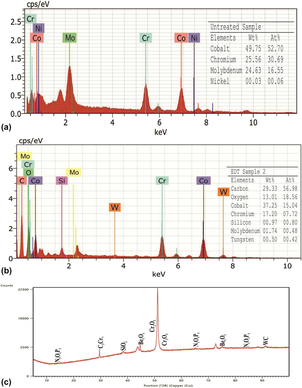
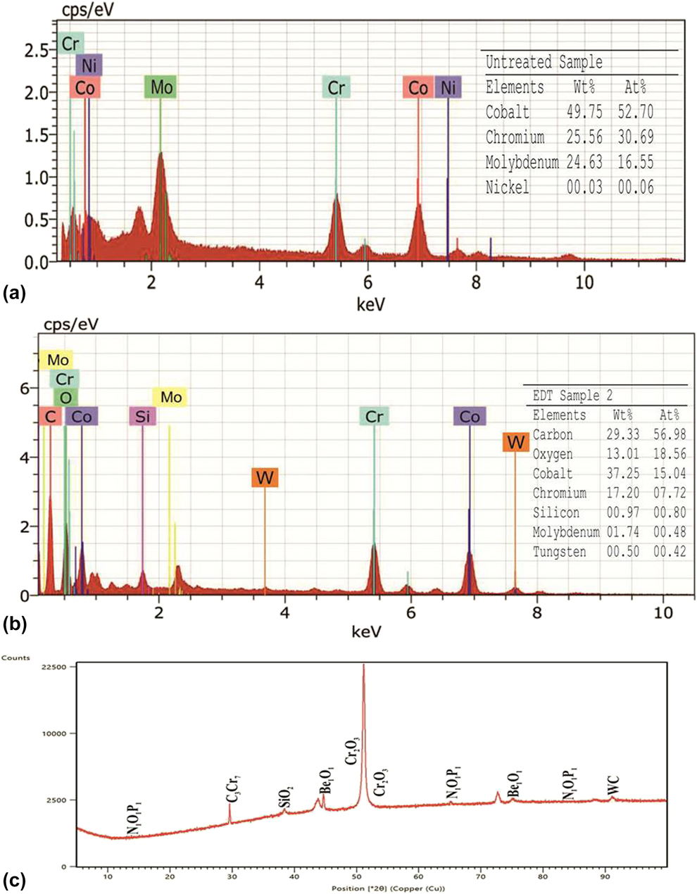
The energy-dispersive X-ray spectroscopy (EDX) spectrum of the unmachined and EDT sample 2 exhibit excellent results of biocompatibility and wear are illustrated in Figs. 5(a) and 5(b). Both specimens observed with the existence of basic elements of Co–Cr implant alloy, such as Cr, Co, Ni, and Mo, on the surface. However, the EDT sample was observed with the oxygen and carbon elements apart from base elements of the implant material [Fig. 5(b)]. The EDX results of phase formation on the EDT sample are also affirmed by the X-ray diffraction (XRD) pattern [Fig. 5(c)]. The formation of compounds such as cubic structured beryllium oxide (Be1O1), hexagonal structured chromium oxide (Cr2O3), tetragonal structured silicon dioxide (SiO2), and monoclinic structured phosphorous nitride (N1O1P1) on the EDT surface promotes the cell viability or enhance the biocompatibility of the implant [Reference Mahajan and Sidhu24, Reference Jenko, Gorensek, Godec, Hodnik, Batic, Donik and Dolinar25, Reference Im, Akiyama, Habazaki, Kawashima, Asami and Hashimoto26]. However, the formation of the carbide phases such as the orthorhombic structure of chromium carbide (C3Cr7) and hexagonal structured tungsten carbide (WC) on modified sample results in the harder surface [Reference Wu, Zhou and Tang27, Reference Weng, Wang, Wu, Wang and Yang28], which enhances the wear resistance of implant surface.
EDS elemental spectrum of (a and b) untreated and EDT sample 2. (c) XRD pattern of EDT sample 2.
Discussion
The major aim of this study is to scrutinize the cytocompatibility (biocompatibility) and tribological behavior of electrical discharge treated Co–Cr implant alloy. The MTT assay was performed on the substrates for evaluating the percentage cell viability. Among all samples (untreated and EDT), sample 2 was observed with higher cell viability (∼88%, optical density = 0.676, P < 0.05). The large numbers of living cells were observed on the sample surface. The MG63 cell viability of sample 2 was approximately reformed as 1.9 times greater than that of the unmachined sample. Similarly, sample 2 also demonstrated excellent results for wear resistance (1.2 × 10⁻⁷ mm3/Nm or 0.02 mm3) and for the coefficient of friction (0.29). The formation of oxide-rich tribochemical layers, nitrides, phosphides, and carbides enhanced the biocompatibility and decreased the wear damage. Evidently, during EDT, at high temperature, the chemical reaction between molten base elements and water (dielectric fluid) results in the formation of oxides and carbides on the surface, which changes the surface chemistry of the material. Therefore, EDT Co–Cr implant alloy (sample 2) avowed excellent wear resistance as well as percentage cell viability, which affirmed the best parameters for the manufacturing of efficient Co–Cr implant. However, the cytotoxicity results of sample 1 were almost close to those of the sample 2 (best sample), but the wear resistance outcomes of sample 1 were not favorable. As earlier represented in Fig. 4(b), the existence of craters and pores on the surface could be the probable reason for the formation of deeper grooves and scratches during the wear test. Although the tribochemical layers were also formed on the surface of sample 1, it could appear after the formation of scratches. It is believed that these tribochemical layers are time dependent or could be evolved after some time during the wear test [Reference Sahasrabudhe, Bose and Bandyopadhyay16]. Another essential reason in the decrement of wear resistance is the low value of the microhardness of the surface. The microhardness value at 5 A current treated surface (sample 1) was found to be 476 HV0.2, which is too low compared to microhardness of 10 A current treated sample 2 (773 HV0.2). Keeping in view that microhardness depends on the amount of molten material deposition on the surface during EDT process at variant current and pulse on-time. Furthermore, increasing the current up to 16 A (sample 3) results in the formation of irregular surface (large craters, ridges, and resolidified metallic droplets), which exhibits multiple scratches and debris on the surface during wear testing, affirming the low-grade wear resistant surface. The cytocompatibility and tribological responses of Co–Cr implant alloy are compared with those reported in previous studies.
In vitro cytocompatibility
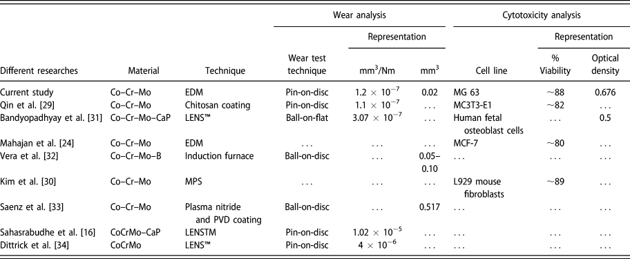
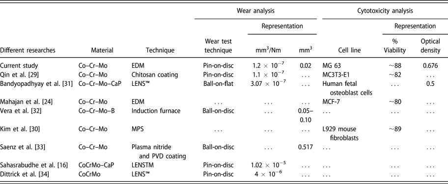
In our earlier study [Reference Mahajan and Sidhu24], the Co–Cr samples were treated with graphite electrode using the full factorial method and spark energy range of machining was determined. In that study, the cytocompatibility of EDT Co–Cr samples was calculated by computing MCF-7 (Michigan Cancer Foundation-7, human adenocarcinoma) % cellular viability, and the best sample of that research exhibited 80% cell viability. Likewise, Qin et al. [Reference Qin, Feng, Hafezi, Zhang, Guo, Dong and Qin29] fabricated the Co–Cr–Mo alloy by chitosan coating and analyzed the (MC3T3-E1) cell viability. The results affirmed the enhanced % cellular viability of chitosan-coated Co–Cr–Mo alloy (∼82%). Kim et al. [Reference Kim, Kim, Son, Min, Kim and Kwon30] prepared the Co–Cr–Mo alloy via milling/post-sintering (MPS) and casting techniques. They analyzed the cytotoxicity of the surfaces by computing the L929 mouse fibroblasts cells and reported MPS technique manufactured alloy exhibited higher % cell viability (∼88%) as compared to casting method. However, Bandyopadhyay et al. [Reference Bandyopadhyay, Shivaram, Isik, Avila, Dernell and Bose31] analyzed the optical density (OD) of human fetal osteoblast cells on the laser engineered net shaping (LENS™) and laser surface melting (LSM) processed CoCrMo–CaP composite coated alloy surfaces. The best sample of their in vitro biocompatibility study was witnessed with 0.5 OD.
Wear resistance
Along with % cell viability, Qin et al. [Reference Qin, Feng, Hafezi, Zhang, Guo, Dong and Qin29] also analyzed the wear performance of Co–Cr–Mo alloy on a pin-on-disc tribometer. The wear rate observed for the chitosan-coated surface was 1.1 × 10⁻⁷ mm3/Nm (almost equal to the present study). However, Alvarez-Vera et al. [Reference Alvarez-Vera, Juarez-Hernandez, Gonzalez-Rivera, Mercado-Solis and Hernandez-Rodriguez32] added boron in Co–Cr alloy by utilizing an induction furnace technique. They utilized a ball-on-disc technique for evaluating the wear responses on the surface. The volumetric wear damage on the modified surface was observed in between (0.05–0.10 mm3). Similarly, Ortega-Saenz et al. [Reference Ortega-Saenz, Hernandez-Rodriguez, Ventura-Sobrevilla, Michalczewski, Smolik and Szczerek33] reported the volumetric wear damage of plasma nitride and physical vapor deposition (PVD)-coated Co–Cr–Mo alloy as 0.517 mm3. Dittrick et al. [Reference Dittrick, Balla, Davies, Bose and Bandyopadhyay34] processed the Co–Cr–Mo alloy by LENS™ technique and utilized a pin-on-disc technique for evaluating the wear performance of the substrates. The reported wear rate was 4 × 10⁻⁶ mm3/Nm. Sahasrabudhe et al. [Reference Sahasrabudhe, Bose and Bandyopadhyay16] reported the wear rate of LENS™ processed CoCrMo–CaP composites as 1.02 × 10⁻⁵ mm3/Nm. However, Bandyopadhyay et al. [Reference Bandyopadhyay, Shivaram, Isik, Avila, Dernell and Bose31] reported the wear rate of LENS™ along with LSM technique processed CoCrMo–CaP as 3.07 × 10⁻⁷ mm3/Nm. The tribofilm layers of CCM3 increased the wear resistance of the specimens.
Hence, from our present study, it was observed that EDT Co–Cr substrate (sample 2) exhibited enhanced wear resistance and cytocompatibility compared with earlier reported researches. Table III summarizes the % cell viability and wear damage of earlier researches. The table shows the comparison of EDT Co–Cr–Mo alloy’s wear behavior and cytocompatibility responses of the present study with earlier reported researches. The treatment of Co–Cr implant alloy substrates at 10 A current, 60 µs pulse on-time, and 150 µs pulse off-time offered most favorable biocompatibility and tribological behavior results. The surface modification of Co–Cr implant by thermoelectric technique (EDT), considering the above process parameters, also exhibited excellent corrosion resistance and hemocompatibility responses, as discussed in our recent study [Reference Mahajan and Sidhu18].
Comparison of EDT processed Co–Cr implant alloy’s cytotoxicity and wear performance with previously reported studies.
Conclusions
The medical-grade Co–Cr alloy surface was treated by EDM to examine the biological performance and tribological behavior. In this study, the EDT samples were compared with the unmachined sample and the conclusions are drawn as follows:
(1) The cytotoxicity test examined the in vitro biocompatibility responses of the samples. The results revealed that the viability of the MG-63 cells on EDM samples was higher than that of the unmachined sample. The outcomes of the treated sample established the superior biocompatibility.
(2) The tribological results demonstrated that the modified sample has better wear resistance and frictional factor.
(3) XRD pattern and EDX spectrum analysis substantiated the oxide and carbide compounds on the machined surface that promote the biocompatibility and wear resistance of the EDM surface.
(4) The treatment of Co–Cr alloy at 10 A current, 60 µs pulse on-time, and 150 µs pause time delivered favorable results of biocompatibility and tribological performance.
(5) Therefore, EDT Co–Cr implants can be recommended for utilizing in orthopedic surgeries. Furthermore, the research can be prolonged to examine the surface wettability, residual stresses, etc., of machining surfaces.
Methodology
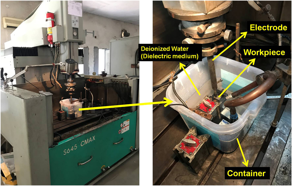
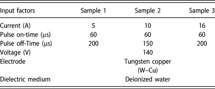
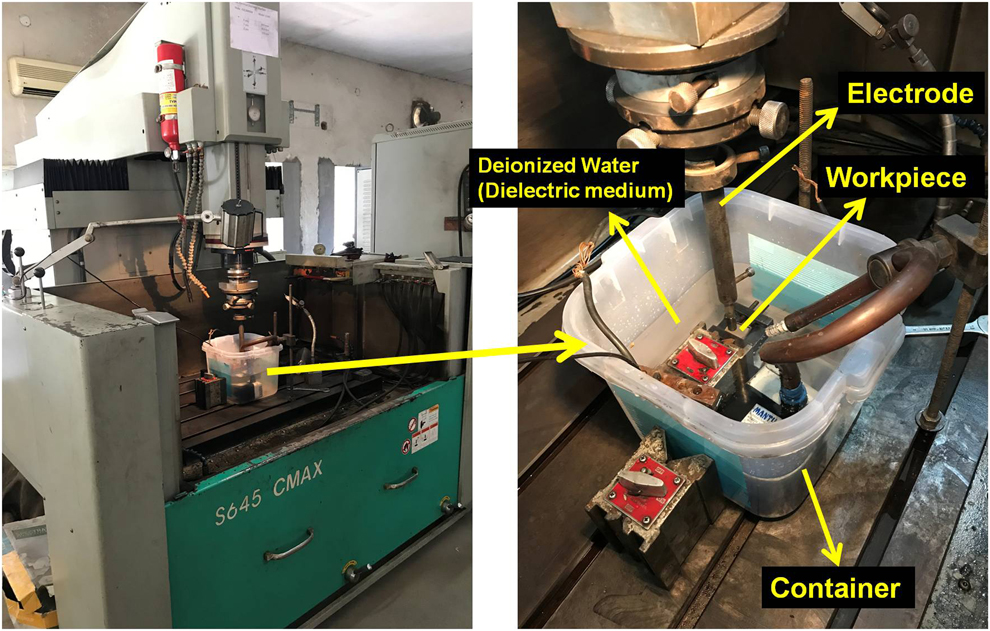
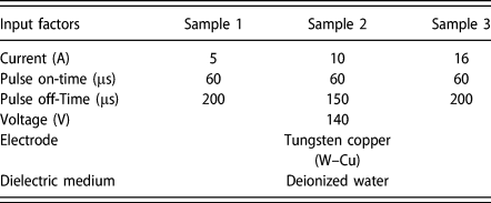
In the current study, the rectangular plate of medical-grade F-90(Co–20Cr–15W–10Ni) alloy (size of 50 mm length with 30 mm thickness) was supplied by Siora Surgicals (New Delhi, India), which is a substantial material that has significant applications in the orthopedic field. Initially, the surface of the plate was mechanically finished with emery paper [material: silicon carbide (SiC), grit-800], followed by cleaning with an ethanol solution (BioIndus Chemical Pvt Ltd., Mumbai, India). Furthermore, the plate was fixed in the dielectric liquid tank of EDM (make: OSCARMAX, Model-S 645, Taichung, Taiwan) for machining. The material exclusion mechanism in the EDM process is based on the principle of regular discharges of spark between workpiece and tool electrode (both immersed in dielectric fluid). The spark gap, pulse duration, polarity, and most important intensity of current (the performance parameters) decided the metal removal rate during the process. After the EDT, the machined region was removed in a circular form (10 mm diameter and 30 mm thickness) from the plate by wire EDM for the further tests. The pictorial view and experiment arrangement of the EDM machine is presented in Fig. 6. The previous research literature was taken as a resource to select the machining performance parameters in the current study [Reference Mahajan and Sidhu18, Reference Mahajan and Sidhu24], illustrated in Table IV.
EDM machine and Experimental setup of EDM.
Input parameter and their values.
In vitro cytocompatibility test
To analyze the interaction of tissue cells with EDT surfaces, the in vitro cytotoxicity tests were executed. Initially, autoclaving process was performed, where the samples were kept in an autoclave (Accumax, New Delhi, India) for moist heat sterilization (130 °C) for half an hour to prevent contamination from microorganisms, such as bacteria, algae, and fungi. Furthermore, cell proliferation and cytotoxicity of specimens were resolute using MTT [3-(4,5-dimethylthiazol-2-yl)-2,5-diphenyltetrazolium bromide] [C18H16BrN5S] assay in MG 63-Human Bone Osteosarcoma cell line (NCCS, Pune, India) by the following reported protocol. Camptothecin (CPT 25 µm; Sigma, Pune, India) was utilized as a positive control, which caused a significant toxic effect on intact cells [Reference Srivastava, Negi, Kumar, Gupta and Khanuja35, Reference Horwitz, Chang and Grollman36], and Dulbecco’s Modified Eagle Medium (DMEM; Dealer: Himedia, Mumbai, India) was considered as a negative control due to its cell maintenance capability and observed with 100% cell viability. Briefly, cells were grown in DMEM with 10% fetal bovine serum, 4500 mg/L of glucose, L-glutamine, sodium bicarbonate, and sodium pyruvate. These cells were preserved for 24 h in a 5% CO2 atmosphere at 37 °C (Incubator-HF100; Heal Force, Shanghai, China). After that, the cells were subcultured in a 24-well plate (Thomas Scientific, Swedesboro, New Jersey) at a required cell density of 50,000 cells per well-containing metal disc samples (dimensions: 10 mm in diameter and 2.5 mm thickness). After the 48 h incubation period, the metal samples were removed from plate and MTT reagent (Dealer: Himedia, Mumbai, India) was added to the final concentration of 0.5 mg/mL of total volume. The plate was again placed in an incubator and incubated for 3 h. After that, the amount of cell viability was specified by the transformation of water-soluble tetrazolium dye MTT to purple-colored formazan crystals by metabolically lively cells. Furthermore, the color transformation was compared with the positive control (camptothecin) and negative control (DMEM media) samples. To measure the OD of the cells, the MTT reagent was removed from the well plate and then by adding 1000 µL of dimethyl sulfoxide (DMSO), the cells were solubilized. By utilizing the spectrophotometric technique at 570 nm, the OD of the released solubilized formazan reagent was measured. Later, all experiments were executed in triplicate. The % cell viability was evaluated by the following formula:
 $$\% \;{\rm{Cell}}\;{\rm{viability}} = {{{\rm{ABs}}} \over {{\rm{ABn}}}} \times 100\quad ,$$
where ABs is the absorbance of the testing specimens and ABn is the absorbance of the negative control.
Pin-on-disc wears studies
The wear test for Co–Cr specimens was performed by employing a pin-on-disc type tribometer provided by DUCOM Instruments (Bangalore, India). The disc of EN31 steel was utilized with the dimension of 120 mm in diameter and 10 mm in thickness. The samples were prepared in the form of pins (via soldering with the same material) with 45 mm length and 10 mm diameter. The Ringer solution was utilized as a test lubricant, whereas the main wear track diameter for pins was considered as 80 mm. The pins were consistently loaded on the disc with a steady weight of 70 N and rotating speed (disc) of 100 rpm and the time duration was set at 3600 s for each experiment. The wear track and specimens were washed with acetone, and all the experiments were performed three times (n = 3) at ambient temperature. The control of the operation parameters and calculation of wear and friction values between pin and disc were obtained with the utilization of computer and the associated software (TR-20LE), whereas the material wear rates (WR, in mm3/Nm) were calculated from the mass loss technique of specimens and expressed as follows:
 $${\rm{WR}} = {{\Delta m} \over {L \times \rho \times W}}\quad ,$$
where Δm represents the mass loss in grams, L is the total sliding distance in meters, ρ denotes the density of pin material (for Co–Cr material: ρ = 8.3 g/mm3), and W is the applied load in Newton. The pins mass loss was obtained by utilization of precise weighing machine (Saffron Electronic Scale, Gujarat, India) having an accuracy of ±0.1 mg.
FESEM/EDX and XRD analysis
FESEM (Hitachi SU-8010, Tokyo, Japan) technique was employed to scrutinize the wear characteristics of the EDT substrates. The chemical characterization and elemental composition of the Co–Cr alloy were analyzed by EDX spectroscopy. Moreover, XRD (PANalytical X’Pert Pro MPD, Malvern Panalytical, Etten Leur, the Netherlands) using Cu Kα X-ray radiation examined the phase formation and material transferred on the modified surface.
Supplementary material
To view supplementary material for this article, please visit https://doi.org/10.1557/jmr.2019.240.
Acknowledgments
The authors thank IKG Punjab Technical University, Kapurthala, for its support of this research work.