1. INTRODUCTION
Hot electrons from a solid target irradiated by an intense laser pulse impinge on the target and ionize the K-shell electrons of atoms, which lead to the emission of characteristic X rays and bremsstrahlung (Chen et al., Reference Chen, Gregori, Patel, Chung, Evans, Freeman, Saiz, Glenzer, Hansen, Khattak, King, Mackinnon, Notley, Pasley, Riley, Stephens, Weber, Wilks and Beg2007; Toth et al., Reference Toth, Fourmaux, Ozaki, Servol, Kieffer, Kincaid and Krol2007). The generated short-pulse and monoenergetic K
α radiation can be used to diagnose a dense plasma, image ultrafast biomedical, probe lattice dynamics, photo-ionize the 1s electron in neon, and so on (Sokolowski-Tinten et al., Reference Sokolowski-Tinten, Blome, Blums, Cavalleri, Dietrich, Tarasevitch, Uschmann, Förster, Kammler, Horn-von-Hoegen and von der Linde2003; Park et al., Reference Park, Chambers, Chung, Clarke, Eagleton, Giraldez, Goldsack, Heathcote, Izumi, Key, King, Koch, Landen, Nikroo, Patel, Price, Remington, Robey, Snavely, Steinman, Stephens, Stoeckl, Storm, Tabak, Theobald, Town, Wickersham and Zhang2006; Pikuz et al., Reference Pikuz, Faenov, Magnitskiy, Nagorskiy, Tanaka, Ishino, Nishikino, Fukuda, Kando, Kato and Kawachi2014b
; Nilsen, Reference Nilsen2016). Femtosecond Petawatt-class laser pulses with relativistic intensities I >1021 W cm−2 incident on solid foils can produce X-ray radiation with intensities in the keV range exceeding ~I >1017 W cm−2 by observation of KK hollow ions (Colgan et al., Reference Colgan, Faenov, Pikuz, Tubman, Butler, Abdallah, Dance, Pikuz, Skobelev, Alkhimova, Booth, Green, Gregory, Andreev, Lötzsch, Uschmann, Zhidkov, Kodama, McKenna and Woolsey2016; Pikuz et al., Reference Pikuz, Skobelev, Alkhimova, Pokrovskii, Colgan, Pikuz, Faenov, Soloviev, Burdonov, Eremeev, Sladko, Osmanov, Starodubtsev, Ginzburg, Kuz¡¯min, Sergeev, Fuchs, Khazanov, Shaikin, Shaikin and Yakovlev2017). Such powerful X-ray sources can produce and probe exotic material states with high densities and multiple inner-shell electron excitations even for higher Z elements (Colgan et al., Reference Colgan, Abdallah, Faenov, Pikuz, Wagenaars, Booth, Culfa, Dance, Evans, Gray, Kaempfer, Lancaster, McKenna, Rossall, Skobelev, Schulze, Uschmann, Zhidkov and Woolsey2013; Pikuz et al., Reference Pikuz, Faenov, Skobelev and Fortov2014a
; Faenov et al., Reference Faenov, Colgan, Hansen, Zhidkov, Pikuz, Nishiuchi, Pikuz, Skobelev, Abdallah, Sakaki, Sagisaka, Pirozhkov, Ogura, Fukuda, Kanasaki, Hasegawa, Nishikino, Kando, Watanabe, Kawachi, Masuda, Hosokai, Kodama and Kondo2015a
). For practical applications and diagnoses, of importance is to enhance the brightness or the yield of K
α photons and the conversion efficiency
 ${\rm \eta} _{L \to K_\alpha } $
from the laser energy to K
α photons energies. In the interaction of an intense laser pulse with a thick target (tens of mm), the collisional stopping range of fast electrons is usually larger than the attenuation length of K
α photons, which makes the photons easily absorbed by the target material. For the thin foil (tens of μm), the majority of accelerated energetic electrons can move forward, traverse the foil and reach the rear surface of the foil. An electric field is inevitably established in a thin sheath near the surface and it prevents the electrons from escaping and reflects electrons back into the target. Subsequently, the reversed electrons can transport again in the target, some of them can arrive at the front surface of the target, a similar sheath electric field is built before the target in the same way, and it pulls electrons into the foil again. The actions of pulling electrons into the target both at the front and rear surfaces may do execution repeatedly. Therefore, the energetic electrons can interact with the target again and again until their energies are exhausted. This phenomenon is called the electron refluxing effect (Bell et al., Reference Bell, Davies, Guerin and Ruhl1997; Sentoku et al., Reference Sentoku, Cowan, Kemp and Ruhl2003), which will affect K
α radiation yield, the duration of the X-ray pulse as well as the size of X-ray radiation source.
Recently, Faenov et al. emphasize two regimes in a laser-produced plasma [the radiation dominant regime (RDR) and the radiation dominant kinetics regime (RDKR)], RDR and RDKR demonstrate strong influence of the electron refluxing on the X-ray and γ-radiation processes in the laser-produced plasma (Nakamura et al., Reference Nakamura, Koga, Esirkepov, Zh., Kando, Korn and Bulanov2012; Pandit & Sentoku, Reference Pandit and Sentoku2012; Faenov et al., Reference Faenov, Colgan, Hansen, Zhidkov, Pikuz, Nishiuchi, Pikuz, Skobelev, Abdallah, Sakaki, Sagisaka, Pirozhkov, Ogura, Fukuda, Kanasaki, Hasegawa, Nishikino, Kando, Watanabe, Kawachi, Masuda, Hosokai, Kodama and Kondo2015a ). Ultra-relativistic and high-power laser is focused onto a thin metal foil and creates a central zone at the laser focus, where the radiation process begins to dominate over the electron dynamics in the interaction, reaching the RDR plasma zone (Zhidkov et al., Reference Zhidkov, Koga, Sasaki and Uesaka2002; Pandit & Sentoku, Reference Pandit and Sentoku2012; Ridgers et al., Reference Ridgers, Brady, Duclous, Kirk, Bennett, Arber, Robinson and Bell2012). The RDKR is that regime where X rays from the central plasma zone dominate the standard collisional atomic processes in the peripheral plasma, thereby creating exotic states of matter composed of hollow atoms with multiple inner-shell excitations, which are diagnosed through the observation of unique spectral lines (Colgan et al., Reference Colgan, Abdallah, Faenov, Pikuz, Wagenaars, Booth, Culfa, Dance, Evans, Gray, Kaempfer, Lancaster, McKenna, Rossall, Skobelev, Schulze, Uschmann, Zhidkov and Woolsey2013; Pikuz et al., Reference Pikuz, Faenov, Colgan, Dance, Abdallah, Wagenaars, Booth, Culfa, Evans, Gray, Kaempfer, Lancaster, McKenna, Rossall, Skobelev, Schulze, Uschmann, Zhidkov and Woolsey2013; Hansen et al., Reference Hansen, Colgan, Faenov, Abdallah, Pikuz, Skobelev, Wagenaars, Booth, Culfa, Dance, Tallents, Evans, Gray, Kaempfer, Lancaster, McKenna, Rossall, Schulze, Uschmann, Zhidkov and Woolsey2014). The RDKR occurs at far lower laser intensities than the radiation damping regime where radiation dominates particle dynamics (Zhidkov et al., Reference Zhidkov, Koga, Sasaki and Uesaka2002; Kostyukov et al., Reference Kostyukov, Nerush and Litvak2012; Nakamura et al., Reference Nakamura, Koga, Esirkepov, Zh., Kando, Korn and Bulanov2012). Due to the electron refluxing effect, ionized electrons drive ion acceleration, resulting in rapid plasma expansion, and radiate X-ray photons up to very high energies (Faenov et al., Reference Faenov, Colgan, Hansen, Zhidkov, Pikuz, Nishiuchi, Pikuz, Skobelev, Abdallah, Sakaki, Sagisaka, Pirozhkov, Ogura, Fukuda, Kanasaki, Hasegawa, Nishikino, Kando, Watanabe, Kawachi, Masuda, Hosokai, Kodama and Kondo2015a , Reference Faenov, Skobelev, Pikuz, Pikuz, Kodama and Fortov b ).
In numerical simulation, the common method of studying the electron refluxing is specularly reflected electron iterations combining particle-in-cell (PIC) and Monte Carlo simulation. When fast electrons propagate in the target, it is assumed that a part of electrons are reflected at the front and rear surfaces of the foil. The energies of reflected electrons are recalculated and their direction vectors are specular symmetrically transformed, which is used as an input of the next iteration step. Several iteration steps may be implemented until these electrons lose all their energies. Fiorini et al. (Reference Fiorini, Neely, Clarke and Green2014) use initial theoretical electron spectra, cold targets, and refluxing electrons forced to re-enter the target iteratively to predict the maximum possible yield of X rays with the Monte Carlo code Fluka. But the reactions due to the electric field occurring in the target cannot be simulated using Fluka. Quinn et al. (Reference Quinn, Yuan, Lin, Carroll, Tresca, Gray, Coury, Li, Li, Brenner, Robinson, Neely, Zielbauer, Aurand, Fils, Kuehl and McKenna2011) utilize a fixed Cu layer backed with a CH layer and varies the thickness of CH layer to control the number of the refluxing electrons. The boundaries of the simulation space are fully reflective and therefore the whole fast electron population is refluxed within the target. Myatt et al. (Reference Myatt, Theobald, Delettrez, Stoeckl, Storm, Sangster, Maximov and Short2007) had studied the percentage of refluxing electrons in one iteration step and pointed that the number of refluxes changed with the target and the laser characteristics. The electron refluxing is intrinsic for the transport of fast electrons in thin solid target, and it is worth to investigate and clarify the influence of the electron refluxing on K α radiation. But there have been few direct investigations in numerical simulation. In this paper, the electric fields are directly added at the front and rear surfaces of the foil to give an analogy with the electron refluxing in Monte Carlo code Geant4 (Agostinelli et al., Reference Agostinelli, Allison, Amako, Apostolakis, Araujo, Arce, Asai, Axen, Banerjee, Barrand, Behner, Bellagamba, Boudreau, Broglia, Brunengo, Burkhardt, Chauvie, Chuma, Chytracek, Cooperman, Cosmo, Degtyarenko, Dell'Acqua, Depaola, Dietrich, Enami, Feliciello, Ferguson, Fesefeldt, Folger, Foppiano, Forti, Garelli, Giani, Giannitrapani, Gibin, Gómez Cadenas, González, Gracia Abril, Greeniaus, Greiner, Grichine, Grossheim, Guatelli, Gumplinger, Hamatsu, Hashimoto, Hasui, Heikkinen, Howard, Ivanchenko, Johnson, Jones, Kallenbach, Kanaya, Kawabata, Kawabata, Kawaguti, Kelner, Kent, Kimura, Kodama, Kokoulin, Kossov, Kurashige, Lamanna, Lampén, Lara, Lefebure, Lei, Liendl, Lockman, Longo, Magni, Maire, Medernach, Minamimoto, Mora de Freitas, Morita, Murakami, Nagamatu, Nartallo, Nieminen, Nishimura, Ohtsubo, Okamura, O'Neale, Oohata, Paech, Perl, Pfeiffer, Pia, Ranjard, Rybin, Sadilov, Salvo, Santin, Sasaki, Savvas, Sawada, Scherer, Sei, Sirotenko, Smith, Starkov, Stoecker, Sulkimo, Takahata, Tanaka, Tcherniaev, Tehrani, Tropeano, Truscott, Uno, Urban, Urban, Verderi, Walkden, Wander, Weber, Wellisch, Wenaus, Williams, Wright, Yamada, Yoshida and Zschiesche2003). Otherwise, a theoretical model is proposed to give the sheath electric fields at both sides of foil, and the fields depend on the characters of hot electrons and the laser.
The paper is organized as follows. Section 2 presents the theoretical model of the sheath potential at the front and rear surfaces of the target. Section 3 shows the simulation results and we investigate comparatively the dependency of K α photons yield with and without the refluxing effect on the electron temperature and the target thickness. The influence of the electron refluxing on the size of K α spot is also discussed. The conclusion is given in Section 4.
2. SIMULATION IMPLEMENTATION OF ELECTRON REFLUXING
The transport of hot electrons through the solid target is simulated by using the Monte Carlo code Geant4. The target is assumed to be a 10-μm-thick copper slab of a homogeneous material. Based on laser–target interactions in the experiments, a set of incident hot electrons is initialized with energies between 0.02 and 15 MeV (Cao et al., Reference Cao, Gu, Zhao, Cao, Huang, Zhou, Cai, He, Yu and Yu2010; Zhao et al., Reference Zhao, Cao, Cao, Wang, Huang, Jiang, He, Wu, Zhu, Dong, Ding, Zhang, Gu, Yu and He2010). They are emitted from a round surface with a radius of 10 µm, and the emitted angles relative to the Z-axis are randomly uniformly chosen between 0 and θ. The configuration of Geant4 in this work is similar to our previous work (Zhao et al., Reference Zhao, Zheng, Cao, Zhao, Li, Gu and Liu2016). It covers the angular and energy distributions of injected hot electrons in the activity, the interaction processes (including the electron-impact ionization, the electron scattering, the creation of K α radiation, and bremsstrahlung), the visualization package, and other diagnoses in the simulations. The energy spectrum of hot electron beam resembles as a Boltzmann distribution (Sokolowski-Tinten et al., Reference Sokolowski-Tinten, Blome, Blums, Cavalleri, Dietrich, Tarasevitch, Uschmann, Förster, Kammler, Horn-von-Hoegen and von der Linde2003; Gu et al., Reference Gu, Cai, Zheng, Yang, Zhou, Jiao, Chen, Wen and Chunyu2005):
 $$f\,(E)\,{\rm \sim} \exp \left( {\displaystyle{{ - E} \over {T_{\rm e}}}} \right),$$
where E and T e denote the energy of hot electrons and the electron temperature, respectively.
When fast electrons reach the rear surface of the target, some of the hottest electrons escape from the foil and establish a strong electric field (up to the order of TV m−1), which pulls most of the electrons back into the target. A similar field also forms at the front of the target. In our Geant4 model, the electric fields are recruited both at the front and rear surfaces of the target with opposite directions to simulate the electron refluxing effect. The distributions of the electric fields, with the direction normal to the target along the Z-axis, are given by
 $$E_z = - E_0 \exp \left( {\displaystyle{z \over b}} \right)\quad (z \le 0),$$
and
 $$E_z = E_0 \exp \left( {\displaystyle{{ - z + 10} \over b}} \right)\quad (z \ge 10\;{\rm \mu m}),$$
where b ~ 0.1 μm, is the scale length of the sheath field. z = 0 and 10 μm represent the front and rear surfaces of the target, respectively. A valid value of E 0 for the sheath field in Eq. (2) can be estimated based on Mora's plasma expansion model (Mora, Reference Mora2003), that is,
 $$E_0 = \displaystyle{{\sqrt 2 T_{\rm e}} \over {e {\rm \lambda} _{{\rm De}}}}, $$
where e is the elementary charge. λDe is the Debye length of the electrons
 $$\lambda _{{\rm De}} = \sqrt {\displaystyle{{{\rm \varepsilon} _0 T_{\rm e}} \over {n_{\rm e} e^2}}}, $$
where n e is the electron density and ε0 is the permittivity of vacuum. Assuming simple ballistic transport of the fast electrons through the target at a fixed beam divergence angle, the volume of the electron cloud on the back of the target is given as
 $$V = c \hskip0.5pt{\rm \tau} _{{\rm laser}} {\rm \pi} (r_0 + d\tan {\rm \theta} )^2, $$
where c is the light velocity, τlaser is the laser pulse duration, r 0 is the radius of incident electron spot, d is the thickness of the target, and θ is the half-angle of incident electrons.
Therefore, the electron density on the back of the target is
 $$n_{\rm e} = \displaystyle{{N_{\rm e}} \over V} = \displaystyle{{N_{\rm e}} \over {c \hskip0.5pt{\rm \tau} _{{\rm laser}} {\rm \pi} (r_0 + d\tan {\rm \theta} )^2}}, $$
where N e is the total number of electrons. By substituting Eq. (6) into Eq. (4) and combining Eq. (3), the electric field E 0 can be obtained
 $$E_0 = \sqrt {\displaystyle{{2T_{\rm e} N_{\rm e}} \over {{\rm \varepsilon} _0 c \hskip0.5pt{\rm \tau} _{{\rm laser}} {\rm \pi} (r_0 + d\tan {\rm \theta} )^2}}}. $$
3. SIMULATION RESULTS
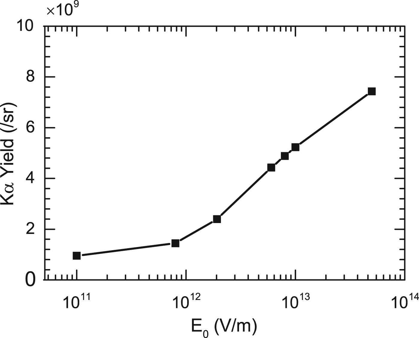
In Figure 1, typically, E 0 is 1.92 × 10¹² V m−1 for the incident electrons and the foil with parameters, T e = 400 keV, N e = 2.6 × 10¹², τlaser = 60 fs, r 0 = 10 μm, d = 10 μm, and θ = 20°. Figure 1 shows that the stronger the electric fields added both at the surfaces is, the more the K α photon yield is. But too weak fields are invalid for increasement of K α photon yield because they cannot pull electrons back to the surfaces. Taking the refluxing into account (i.e. E 0 = 1.92 × 10¹² V m−1), the yield is 2.41 × 10⁹ sr−1, which is several times more than that without the electron refluxing (i.e. E 0 = 0, the yield is 9.26 × 10⁸ sr−1). It is suggested that the electron refluxing has a positive influence on the photon yield.
The variation of K α photon yield with different electric field values E 0. When the refluxing effect is not taken into account (i.e. E 0 = 0), K α photon yield is 9.26 × 10⁸ sr−1.

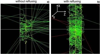
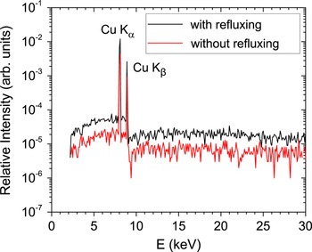
Geant4 visualization package records K α photon tracks (red lines) and the electron tracks (green lines) in the interaction, as shown in Figure 2. The identical hot electron beam penetrates the foil from its left boundary along the Z-axis. Figure 2a shows the tracks of K α photons when the refluxing is not considered. It is displayed that the majority of electrons escape from the rear surface of the target after interacting with target atoms, and a small part is scattered out from the front surface. While in Figure 2b, after taking the electron refluxing into account, most of incident hot electrons are confined in the target, and only the minority of electrons escape from the foil. Due to the electric fields at the front and rear surfaces of the foil, these electrons attempting to escape from the foil will be pulled into the target to interact again with target atoms repetitiously and continually until they lose all the energies. These behaviors can influence K α photon yield, the pulse duration as well as K α source size. Figure 3 compares the X-ray energy spectra from hot electrons interacting with the foil with and without the refluxing effect. It can be seen that considering the refluxing effect or not, the X-ray energy spectra are very distinct. Taking the refluxing effect into account (E 0 = 1.92 × 10¹² V m−1), the energy spectrum (including K α line, K β line, and the bremsstrahlung) is raised. The ratio of K β-to-K α emission and the spectrum contrast ratio of K α to the continuum background are respectively calculated for different target thicknesses. It is found that two ratios do not change with the target thickness increasing, although in the experiments they characterize the degree of the target heating and the quality of X-ray imaging.
K α photon tracks (red lines) and the electron tracks (green lines) plotted by Geant4 visualization package. (a) and (b) correspond to the interaction processes without and with the refluxing effect, respectively. Hot electron beam penetrates the foil from its left boundary along the Z-axis.

Typical spectrum of copper X-ray emission generated by hot electrons–solid target interaction with and without refluxing. The temperature of incident electrons is 400 keV, the target thickness is 10 µm, and the electric field E 0 is 1.92 × 10¹² V m−1.

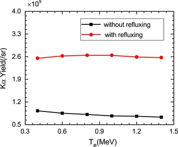
Figure 4 provides the dependency of K α photon yield on the temperature of hot electrons with and without electron refluxing effect for the 10-μm-thick target. It can be clearly seen that K α yield with the electron refluxing effect is 2.7–3.7 times more than that without the refluxing effect for the electron temperatures from 0.4 to 1.4 MeV. Without the electron refluxing, K α yield reduces a little with the temperatures. This result is closely related to the electron-impact K-shell-ionization cross-section for temperatures from 0.4 to 1.4 MeV. It has been analyzed by our previous works (Zhao et al., Reference Zhao, Zheng, Cao, Zhao, Li, Gu and Liu2016). According to Eq. (7), the electric field E 0 rises with the temperature of hot electrons increasing when other parameters of the electron beam and the target are fixed. The stronger the electric field is, the more the reflected electrons are, and it leads to more K α photons. The red line in Figure 4 shows that K α yield almost keeps constant for higher temperatures after including the electron refluxing effect. It can be explained by the joint effect of the electron-impact cross-section and the electron refluxing effect. It is indicated that the yield caused by the refluxing effect compensates the decrease of K α yield from the electron-impact cross-section for higher temperatures.
The dependency of K α photon yield from the 10-μm-thick target on the temperature of hot electrons with and without the electron refluxing effect, respectively.

According to the scaling laws of the temperature of hot electrons (Wilks et al., Reference Wilks, Kruer, Tabak and Langdon1992; Davies, Reference Davies2002; Cao et al., Reference Cao, Pei, Liu, Chang, Li and Zheng2006; Haines et al., Reference Haines, Wei, Beg and Stephens2009):
 $(eT/m_{\rm e} c^2 ) = (1 + a_0^2 )^{1/2} - 1(a_0 = \sqrt {(I {\rm \lambda} ^2 /1.37 \times 10^{18} )} )$
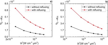
and T(keV) ~ 3.08 × 10⁻⁴ (Iλ2)1/3, the laser strength Iλ2 can be inferred. The laser-to-K
α photon energy conversion efficiency
 $ {\rm \eta} _{L \to K_\alpha } $
with and without the refluxing effect can be calculated assuming the laser-to-electron energy conversion efficiency
 $ {\rm \eta} _{L \to e} = 30\% $
. The dependency of conversion efficiency
 ${\rm \eta} _{L \to K_\alpha } $
on laser strength Iλ2 with and without the refluxing effect is shown in Figure 5. It can be seen that
 $ {\rm \eta} _{L \to K_\alpha } $
with the refluxing effect is higher than that without the refluxing from 2 × 10¹⁸ to 9 × 10¹⁹ W cm−2 μm2.
 $ {\rm \eta} _{L \to K_\alpha } $
decreases gradually with laser strength from 2 × 10¹⁸ to 9 × 10¹⁹ W cm−2 μm2, which agrees with the experimental results of laser–solid interactions in Laser Fusion Research Center (LFRC) of China (Wang et al., Reference Wang, Zhao, He, Zhu, Dong, Wu, Zhang, Niu, Zhou, Xie, Zhou and Gu2015).
The dependency of the conversion efficiency
 ${ (}{\rm \eta} _{L \to K_{\rm \alpha}} {\rm )}$
from the laser energy to K
α X-ray energy on laser strength with and without the electron refluxing effect. (a) and (b) is respectively based on scaling formula
 $(eT/m_{\rm e} c^2 ) = (1 + a_0^2 )^{1/2} - 1(a_0 = \sqrt {(I{\rm \lambda} ^2 /1.37 \times 10^{18} )} )$
and T(keV) ~ 3.08 × 10⁻⁴ (Iλ2)1/3.

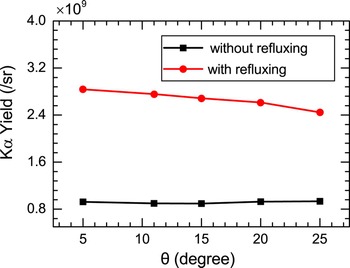
Figure 6 provides K α photon yield for different electron emission angles θ by taking the electron refluxing effect into account or not. With the angle enlarging, K α X-ray production without the refluxing effect slightly rises and then remains constant due to more target atoms participating in the interaction (Zhao et al., Reference Zhao, Zheng, Cao, Zhao, Li, Gu and Liu2016). After taking the refluxing effect into account, the electric fields created at the surfaces of the target weaken gradually with the angle by Eq. (7). It reflects less and less electrons back to target and further results in the yield reducing, as shown by the red line in Figure 6. The results show that the refluxing effect plays a more important role than the emission angle of the electrons in the yield of K α photons.
The variation of K α photon yield from the 10-μm-thick target with the electron emission angles θ with and without the electron refluxing effect, respectively.

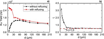
Figure 7a describes the variation of K α photon yield with the target thickness d by considering the refluxing effect or not. A remarkable difference of K α photon yield with and without the electron refluxing is observed as the target thickness increases. K α photon yield without the electron refluxing gradually increases from 7.1 × 10⁸ sr−1 and then stays constant with d. For thinner foils, the number of K α photons rises with d because more target atoms participate in the interaction. But for too thick targets, K α photons can be efficiently absorbed by the target material and not be recorded by a detector. After taking the refluxing into account, K α photon yield decreases from 2.6 × 10⁹ sr−1 and then keeps steady. By Eq. (7), the thick target corresponds to weak electric fields as other parameters are fixed, and too weak electric fields cannot reflect electrons back to the surfaces. As the target thickness d increases, K α yield from the ionization cross-section increases, but the yield from the electron refluxing effect reduces due to weaker electric fields. The variation represented by the red line in Figure 7a indicates the refluxing effect is predominant for K α yield. In addition, for thin targets, the difference of the yields by considering the refluxing effect or not is remarkable. The thinner the target is, the more visible the difference of K α yields is. The results indicate that the influence of the electron refluxing on the K α radiation is more significant for thinner targets.
(a) K α photon yield with and without the refluxing effect as a function of the foil thickness d. (b) The ratio ξ of K α photon yield with the electron refluxing effect to that without the refluxing effect as a function of the foil thickness d. The red line represents ξ = 1.0.

Defining ξ as the ratio of K α yield with the electron refluxing effect to that without the refluxing effect, the variation of ξ with thickness d is depicted in Figure 7b. The ratio reduces rapidly from 3.7 to 1 with the thickness d increasing, which suggests the influence of the refluxing on the K α yield is only valid for the thin target. A critical thickness d c can be achieved by ξ ~ 1, where K α yields are almost equal whether the electron refluxing effect is considered or not. For the target with the thickness d less than d c, the refluxing effect can enhance K α yield with several times. But for the target with the thickness d larger than d c, the refluxing effect is not so effective. Under the conditions, the critical thickness d c is about 30 μm.
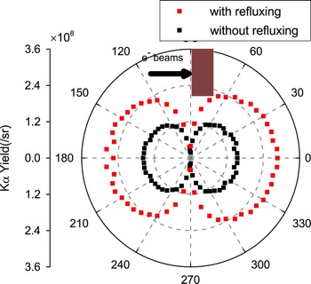
In addition, the angular distributions of K α photons in the interaction of hot electrons with the foil need to be concerned. Figure 8 compares the angular distributions of K α photons from the 10-μm-thick target with and without the electron refluxing effect for the incident electrons with the temperature of 400 keV and the emission angle of 20°. It can be obviously seen that in any detector direction, the number of K α photons with the refluxing effect (E 0 = 3.0 × 10¹² V m−1) is more than that without the refluxing. In the direction of 90° and 270°, few K α photons can be recorded because they can hardly pass through the 3-cm-long distance (the length of the target). After taking the refluxing into account, the number of K α photons moving forward to the rear surface of the target is more than that of those photons moving backward to the front surface of the target. This is because all hot electrons are initially injected forward into the target.
Angular distributions of K α photons from the 10-μm-thick target with and without the electron refluxing effect, respectively. The temperature of incident electrons is 400 keV.

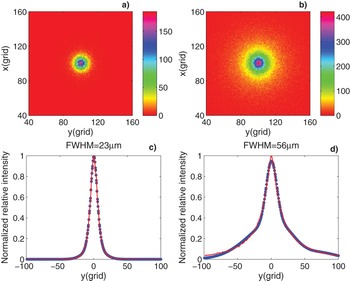
Furthermore, the influence of the electron refluxing on the size of K α X-ray source is shown in Figure 9. Figure 9a and 9b are K α X-ray spot images detected at z = 15 μm behind the foil. Figures 9c and 9d correspond to the emission intensity profiles of Figure 9a and 9b, respectively. Figure 9b displays a remarkable increase in the X-ray spot size after taking the refluxing into account compared to Figure 9a. The full-width at half-maximum (FWHM) increases from 23 to 56 µm after including the refluxing effect (one grid represents 2 µm), and the original radius of incident electron beam is 10 µm. When the hot electrons impact with the foil with an emission angle, they diverge inevitably during the transport process. The electric fields make electrons return to the surface, and these electrons diverge again in the transport, which is clearly plotted in Figure 2b by Geant4 visualization package. So it is the electron refluxing effect, which results in the enlargement of K α spot due to the repeated interactions and scattering between the electrons and the target material.
(a) and (b) are X-ray spot images and (c) and (d) are corresponding the emission intensity profiles at z = 15 μm behind the target. (a) and (c) The refluxing effect is not taken into account and FWHM is 23 µm. (b) and (d) The refluxing effect is taken into account and FWHM is 56 µm. 1 grid = 2 µm. The original radius of the incident electron beam is 10 µm and these electrons with the temperature of 400 keV impinge on the 10-μm-thick target.

4. CONCLUSION
The transport of hot electrons in a solid foil by taking the electron refluxing effect into account is studied by Monte Carlo code Geant4. The electric fields are added both at the front and rear surfaces of the foil to give an analogy with the electron refluxing effect. Therefore, the influence of the refluxing effect on the electron transport and the properties of K
α radiation is directly investigated. This is different from the electron iteration method. Simulation results show that the electron refluxing has an important influence on K
α photon yield and the size of K
α radiation source for thinner targets. K
α yield from the 10-μm-thick target with the electron refluxing effect is 2.7–3.7 times more than that without the refluxing for the electron temperatures from 0.4 to 1.4 MeV. The conversion efficiency
 $ {\rm \eta} _{L \to K_\alpha } $
from laser to K
α photon energy with the refluxing effect is always higher than that without the refluxing, and both of them decrease gradually with laser strength Iλ2. The ratio of K
α yield with the electron refluxing effect to that without the refluxing reduces rapidly from 3.7 to 1 with the target thickness increasing. A critical thickness of the target is achieved to confirm whether the refluxing effect is valid for the target. K
α spot has a remarkable enlargement for the refluxing effect being considered, and it can be attributed to the repeated interactions and scattering between the electrons and the target material.
ACKNOWLEDGMENTS
This work was supported by the National Key Research and Development Program of China (Grant number 2016YFA0401101) and the National Natural Science Foundation of China (Grant numbers 11475030, 11375032, and 11575035).