Introduction
Several satellite payload configurations require input multiplexers (IMUX) to slice a wideband spectrum into narrower channels: this is often done at the uplink frequency after the low noise amplifiers, to avoid aliasing in the frequency converters downstream, and at the downlink frequency after conversion and prior to high power amplification, to avoid that intermodulation products interfere with adjacent channels. An IMUX filter must provide a highly selective response with steep roll-offs at its band edges. This is typically achieved through the implementation of a quasi-elliptic curve which is characterized by a set of transmission zeros symmetrically placed around the passband.
Current solutions for IMUX filters operating at Ka, Q, V bands are based on dual-mode circular waveguide cavities or on dielectric resonators. These configurations allow achieving a high unloaded Q factor which plays an important role in the fulfillment of the most relevant specifications such the flatness of insertion loss and group delay.
The requirement on the absolute insertion loss value is less important for an IMUX filter because it can be compensated by the subsequent amplification stages of the RF chain. Using modern filter synthesis such as the pre-distortion technique, for a fixed Q factor, it is possible to improve the flatness of insertion loss and group delay at the expense of the insertion loss and of the return loss figures. With a pre-distorted design, it is then possible to achieve a flatness that is comparable to the one of a traditional (not pre-distorted) filter but using resonators characterized by lower Q factors. The reflected signals are strongly attenuated by the circulators which are typically used to combine the IMUX channel filters.
The KALOS-DEVAQ program was aimed at the development of critical microwave components (LNA, SSPA, Frequency Converters, Filters, and others) of Q/V band payloads which will be used in future high throughput satellites. The mechanical tolerances tend to be tighter as the frequency increases and are particularly critical at the Q, V frequency bands. For this reason, the selection of the filter configuration was done with a special focus on manufacturability and mechanical tolerances. A novel configuration was then developed and patented which is characterized by a simpler geometry and easier manufacturability than current IMUX filters based on dual-mode circular waveguide cavities or dielectric resonators.
The novel configuration is composed of rectangular waveguide cavities disposed in a multilayer metallic structure. The RF losses are quite higher than those of traditional IMUX filters but, thanks to the application of the pre-distortion technique, the most relevant RF performances (the flatness of insertion loss and group delay) may still be very good. The multilayer structure is better suited for the integration of filters and circulators in a compact design. It is expected that this novel filter configuration may lead to substantial savings of envelope, mass, and cost with respect to the current IMUX solutions. These aspects play an important role in the design of RF payloads embarked on small satellites.
Novel filter configuration
The novel filter configuration, which is covered by the patent [Reference Steffè1], implements, in rectangular waveguide cavities, the folded topology with alternate transversal coupling signs depicted in Fig. 1.
Ideal circuit topology of a filter of order 8.

The waveguide cavities are disposed on two horizontal parallel planes. Those associated with odd resonators of Fig. 1 are laid out on the upper plane while those associated with even resonators are laid out on the lower plane.
The transversal couplings (that is the coupling between on odd resonator and one even resonator of Fig. 1) are realized by slots in the metallic plate which separates the upper and lower waveguides. The longitudinal couplings (that is the coupling between two odd resonators or between two even resonators) are realized by capacitive irises within a common waveguide run.
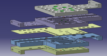
All the mechanical structure is composed of five metal plates of different thicknesses that are stacked up as shown in Fig. 2. The orientation of the rectangular waveguides is such that the E field is parallel to the plates. The waveguide runs are manufactured, by means of wire EDM, as holes through the second and fourth plates. The wire EDM technique is used also for the realization of the couplings slots in the central plate.
Mechanical implementation of the Novel IMUX filter.

All other holes which are visible in Fig. 2 are meant for the fastening screws and for the tuning elements. These holes do not require very tight tolerances and may be done with standard milling machines.
The two waveguide runs are curved in opposite directions (as shown in Fig. 3) in such a way that, in a basic (not pre-distorted) design, the inner geometry is symmetric with respect to a rotation of 180° about a central axis. The perfect symmetry is lost after the application of the pre-distortion technique.
Rotational symmetry (180 deg about red axis).

The waveguide cavities cross the vertical plane containing the symmetry axis at a section on which the electric field achieves a maximum value or a null value depending on the sign of the related transversal coupling. A single coupling slot, centered with the vertical plane, is used at the locations where the transversal electric field (and the longitudinal magnetic field) achieves a maximum value. Two coupling slots, spaced by half wavelength, are used for the other waveguide cavities.
The selected operating mode was TE13 (TE14) for the resonators in which the transversal electric field achieves a maximum (respectively null) condition at the central vertical plane. This mode selection was mainly due to the geometrical constraints, which prescribe a minimum length for a proper allocation of the coupling slots and of the curves.
The special arrangement of the waveguide runs and of the coupling slots allows implementing the alternate signs of the transversal couplings using only inductive slots. The main drawback of other configurations based on mixed inductive and capacitive slots (see in example [Reference Carceller, Soto, Boria and Gulglielmi2]) is that the capacitive slots become too thin when the coupling coefficients are small. The inductive slots are instead characterized by larger dimensions and are less sensitive to manufacturing tolerances.
The different coupling signs associated with the single slot and the double slots can be understood by considering the symmetry properties of the structure and of the magnetic fields with respect to a rotation of 180 degrees about the longitudinal axis depicted in Fig. 3. The basis of the magnetic fields may be selected in such a way that the fields associated with the lower resonators (below the transversal coupling slots) are obtained through a rotation of 180 degrees (about the symmetry axis) of the fields associated with the upper resonators. Under this hypothesis, the longitudinal magnetic fields of two resonators which are related by the 180-degree rotation and are coupled by a single slot have opposite signs at the opposite sides of the slot. The longitudinal magnetic fields associated with two resonators that are coupled by two slots have opposite signs at the opposite sides of different slots because the two slots are exchanged after the rotation. For being the two slots displaced by a half wavelength along the waveguide length, the longitudinal magnetic fields associated with the two resonators must have the same sign at the opposite sides of the same slot.
A folded configuration with the capability to implement a pseudo elliptic response using only magnetic coupling was already published in [Reference Rosenberg3]. This configuration is not symmetric and it has been verified through the design of a four-pole filter with a couple of transmission zeros. According to the author knowledge it has never been used to implement a complex filtering function that requires precise control of several transmission zeros.
The proposed symmetrical configuration offers instead a systematic way to implement a folded circuit of the type shown in Fig. 1 which is characterized by an arbitrary (but even) number N of poles and up to N-2 transmission zeros. An important aspect of the proposed configuration is its capability to compensate the frequency spreading of the coupling coefficients. This can be done tuning the lengths of the capacitive irises (or better of the waveguide sections with reduced heights) associated with the longitudinal couplings. It has indeed experimentally verified that this kind of regulation allows to enforce the symmetry of the pattern of transmission zeros around the central frequency. This symmetry condition is typical of the symmetric folded circuit with constant J inverters shown in Fig. 1.
The electromagnetic tuning was done using a proprietary software tool named EmCAD which is described in [Reference Steffè, Vitulli and Suriani4] and [5]. This tool allows extracting an equivalent circuit (also named the mapped circuit) that represents the frequency response of the physical structure. The filter tuning was driven by the comparison between the parameters associated with the ideal and the mapped circuit.
The general structure of the extracted circuit is slightly different from that one depicted in Fig. 1. The difference affects only the lumped element used to represent the transversal couplings. In Fig. 1, these are represented by J inverters while in the equivalent circuits generated by EmCAD each transversal coupling is represented as the superposition of a J inverter and a resonant element composed of mutual capacitance and a mutual inductance. The mutual capacitance and the mutual inductance are related in such a way that they cancel out at the central frequency of the filter response. This kind of circuit may represent a more general response than the one associated with the circuit of Fig. 1. In fact, it can provide independent control of the transmission zeros without any symmetry constraint.
The frequency spreading of coupling coefficients may then be identified with the amplitude of the resonant coupling terms of the extracted circuit. These terms can be nullified by tuning the lengths of the capacitive irises associated with the longitudinal couplings. In this way, it is possible to achieve an almost perfect agreement between the simulated (full wave) and ideal responses.
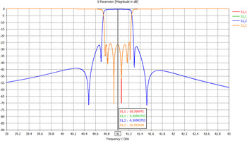
Figure 4 reports the electrical response (simulated with CST microwave studio) associated with a (not pre-distorted) filter of order 6 which is based on a folded topology similar to that one shown in Fig. 1.
Full wave response of a multilayer metallic filter of order 6.

IMUX filter design
In the frame of the program KALOS-DEVAQ the electrical capabilities of the novel configuration have been verified through a few filter designs carried out at Ka, Q and V frequency bands. The mechanical design was improved in a couple of iterations with the realization of a few BB models. In the first iterations, the mechanical configuration was characterized by a smaller number of parts (three instead of five) separated by the symmetry planes of the rectangular waveguides. This configuration minimizes the ohmic losses associated with the contact resistances between adjacent layers but subsequently, it has been verified that these losses may in effect be made negligible through a proper mechanical design of the contact zones and of the fastening screws. The configuration depicted in Fig. 2 is now considered the preferred one because it allows achieving better tolerances at lower manufacturing costs. This configuration has been exploited in the design and development of a V band filter which responds to the electrical specifications given in Table 1. An electrical model of the V band filter (shown in Fig. 7) was manufactured in INVAR and fully tested at ambient temperature and under thermal cycling.
V band filter specifications.

Initially, the filter geometry was defined with reference to a not pre-distorted design with the same topology (the folded circuit of order 8 depicted in Fig. 1). The geometrical structure associated with the initial design is characterized by a perfect symmetry with respect to a rotation of 180° about the central axis depicted in Fig. 3. This symmetry leads to a reduction, by a factor two, of the number of geometrical unknowns and to a simplification of the electromagnetic tuning.
The application of the pre-distortion technique (described in [Reference Cameron, Kudsia and Mansour6]) leads to an ideal circuit that may be regarded as a perturbation of the not pre-distorted circuit. This technique was exploited to compensate the degradation of the Insertion Loss flatness caused by the finite unloaded Q factors (about 3000) at the expense of the input/output matching which was then recovered using isolators.
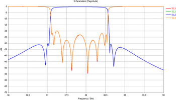
The initial (not pre-distorted) design was used as the starting point for the electromagnetic tuning of the pre-distorted filter. The design parameters of this filter were the passband between 47.220 and 48.630 GHz (enlarged by 5 MHz on both sides with respect to the requirement), the four transmission zeros placed at 47.05, 47.15, 48.7, 48.8 GHz and an equiripple return loss of 25 dB. Figure 5 reports the full-wave response of this filter which was simulated with CST Microwave Studio in order to validate the design performed with the EmCAD code. The comparison between this response and that one predicted by EmCAD code has evidenced a shift of about 90 MHz toward the lower frequencies. This shift has been ascribed to the ohmic losses which were disregarded in the initial design.
Simulated S parameters of the V band not predistorted filter.

The simulated response (S parameter amplitude and group delay) of the pre-distorted design is shown in Figs 6 and 7.
Simulated S parameters of the V band IMUX filter.

Simulated group delay of the V band IMUX filter.

The actual filter configuration includes a set of dielectric elements for the experimental tuning of the resonator frequencies. The experimental tuning was required to compensate the effects of the manufacturing tolerances and of the finite simulation accuracy. Thanks to the tight tolerances (±5 μm) allowed by the wire EDM and because there is no need to tune the coupling coefficients, this activity is much less complex than the tuning of a dual-mode filters.
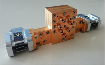
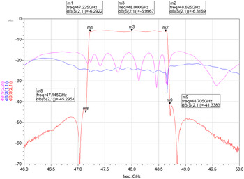
The application of the pre-distortion technique led to an increase of the return loss up to a maximum value of 4 dB but the reflected signals are attenuated by a couple of isolators connected at the two filter ports as shown in Fig. 8. The measured frequency responses of the V band filter (including the input/output isolators) are reported in Figs 9 and 10. From these curves, it may be seen that the electrical performances are fully compliant with the specifications of Table 1. The reported insertion loss of 6 dB includes the contribution of the two isolators. The insertion loss of the filter alone is 4 dB.
V band IMUX filter.

Measured S parameters of the V band IMUX filter.

Measured group delay of the V band IMUX filter.

The equalization of the phase response (group delay) was not addressed in this design because it was not required to meet the given specifications. It is anyway felt that the proposed configuration should be well suited also to implement a more complex filtering function including, in example, a quadruplet of complex transmission zeros aimed at the equalization of the group delay. This assessment, while not yet fully demonstrated with a concrete example, is justified by the capability of the novel configuration to implement a generic folded circuit of the type shown in Fig. 1 without any constraint on the number of resonators/transversal couplings.
Such a complex design would be facilitated by the utilization of the EmCAD software which has the unique capability to compute the complex pattern (in the Laplace plane) of transmission and reflection zeros associated with an electromagnetic structure. This kind of data is very useful to drive the electromagnetic filter tuning and to check that the actual position of the complex quadruplet of transmission zeros matches the ideal pattern.
Conclusions
The Measured results have demonstrated that the novel filter configuration is able to achieve RF performances, in terms of frequency selectivity and flatness of insertion loss, that are comparable with those of more complex solutions based on dual-mode circular waveguide cavities or dielectric resonators. The absolute insertion loss is higher than the one associated with some other solutions but it is still acceptable for most IMUX applications. Thanks to its simple geometry, easy manufacturability, lower production costs and reduced tuning efforts, it is believed that the novel configuration may be a competitive solution for IMUX filters operating at Q/V bands. These aspects play an important role in the design of RF payloads embarked on small satellites.
Patents
The Patent “High-Frequency Selectivity Filter For Microwave Signals” [Reference Steffè1] was registered at the WIPO (World Intellectual Property Organization) in order to protect the novel configuration described in section “The novel filter configuration”.
Acknowledgements
This work was supported by ESA (European Space Agency) under the project KALOS-DEVAQ, Contract number 4000118262/16/NL/US”.
 Walter Steffè received a master degree in electronic engineering from the University of Trieste, Italy in 1990. He joined Thales Alenia Space Italia (TAS-I) in 1991 as a technical staff member of the Antenna Group. Since 2008 he managed several RF Advanced Studies within the RF R&D group of TAS-I. He was involved in the design of microwave components for space-based applications such as microwave filters, antenna feeding networks, array antennas and others. He developed several software tools for electromagnetic simulation and the automated tuning of microwave components. He invented a new numerical method for the modelization, as lumped equivalent circuits, of generic electromagnetic structures. These equivalent circuits may be exploited for the computation of zero/pole patterns associated with the scattering parameters and to drive the electromagnetic tuning of microwave filters.
 Francesco Vitulli graduated in electronic engineering at the University of Rome, Italy in 1987. He joined Thales Alenia Space Italia (TAS-I) in 1989 as a microwave design engineer. He has been Head of Commercial TT&C Equipment's Engineering group till 2011 and then Head of RF Advanced Studies in the Competence Center of Electronic (CCEL) units of TAS Italy. Since 2016 he is the manager in the R&D group in CCEL aiming at the development of innovative onboard equipment's and cutting edge technologies, such as miniaturized microwave filters, compact switch matrices and active microwave filters.