1. Introduction
In fields ranging from fabrication to transportation, and from the health sector to aerospace and agriculture, robot manipulators are a common sight. Recent advancements in engineering systems have given rise to robot manipulators with increasingly complex control systems. Accordingly, robust and effective control of robot manipulators has been one of the important problems of control researchers due to model uncertainties, external disturbances, and nonlinear dynamics [Reference Craig1].
Due to its straightforward design, the proportional-integral-derivative (PID) controller has been predominantly employed for controlling robot manipulators. For robot manipulators subjected to model uncertainties and inconsistent external disturbances, the conventional linear PID controller has sometimes failed to provide the anticipated high performance. In turn, further improved control methods for PID can evolve the control efficiency of robotic manipulators [Reference Bingül and Karahan2]. To illustrate the methods, in ref. [Reference Kumar and Subudhi3], a novel nonlinear self-adjusting PID controller is proposed for regulating the joint position and joint deflection of a flexible-joint manipulator under varying loads. In ref. [Reference Jayaswal, Palwalia and Kumar4], the performance of the PID controller in trajectory control of a two-link robotic manipulator has been investigated for reliable function. In ref. [Reference Shaban, Sayed and Abdelhamid5], a new method for discrete-time PID, named PID+, applied to robotic manipulators has been developed. In ref. [Reference Ege and Kucuk6], a PID controller optimized with a Particle Swarm Optimization (PSO) algorithm is used for energy minimization of a new robotic-type above-knee prosthesis. The complexity of setting PID parameter gains for optimal system performance, including adaptive PID control and PID control utilizing diverse algorithms, as well as trial and error methods, is well-recognized. For its accuracy, robustness, and straightforward application, SMC is frequently chosen as the classical nonlinear control procedure for tracking control issues [Reference Zhang7]. In addition to these important advantages of SMC, the high-frequency chattering that comes with the great gain that reaches the sliding surface causes the robotic manipulator to vibrate, heat up, and lose tracking sensitivity [Reference Sachan, Swarnkar and Nema8]. In order to accomplish the chattering problem, the researchers first resorted to the saturation function instead of the switching function occurring on the sliding surface [Reference Slotine and Li9]. Scholars proposed various hybrids of SMC with smart techniques to control the robot manipulator system [Reference Kumar, Kumar and Rana10]. To boost the efficiency of SMC, researchers have proposed various soft computational ways, like fuzzy logic (FL), fractional order (FO) calculus, artificial neural networks (ANNs), FO (FO) calculus, and adaptive neuro-fuzzy inference system (ANFIS) [Reference Karakuzu11–Reference Milbradt, Evald, Hollweg and Gründling14].
SMC leverages a “switching surface” to manipulate system dynamics. Trajectories starting outside this surface are forced to reach it. The subsequent motion along the surface, termed the "sliding mode," ideally represents infinitely fast switching between control structures. This idealized behavior ensures system convergence to the origin, as detailed in ref. [Reference Roopaei, Shabaninia and Karimaghaee15]. Although a fundamental design for the sliding surface utilizes the error (difference between desired and actual value) and its rate of change, more advanced control strategies may introduce additional modifications. Several approaches regarding the sliding surface with PID have been proffered in the literature. In this context, [Reference Zhang, Li, Li, Chen and Shan16] propounds a novel control framework combining the improved extended high-gain observer (EHGO) and the continuous PID sliding mode controller (PID-SMC). In the study, the Lyapunov approach was used to substantiate the efficacy of EHGO. In the proposed study in [Reference Lochan, Roy and Subudhi17], a proposal is made for robust tip trajectory synchronization between two linked flexible manipulators modeled by the default modes method. This study proposes two control strategies for a robotic manipulator system: a conventional Sliding Mode Control (SMC) for accurate tip trajectory tracking of the main manipulator, and a second-order PID terminal SMC for achieving synchronized motion with rapid tip deflection suppression between the controlled master and identical slave manipulators. The intent of the work proffered in [Reference Loucif and Kechida18] is to present a new SMC-PID antlion optimization algorithm (SMC-PID-ALO) for controlling nonlinear systems, specifically the position of two joints of a 2-DOF robot manipulator. In the study, the robot manipulator was modeled in Simulink, and the control was carried out in MATLAB.
Using SMC together with the FO method provides significant improvements in control performance. In the pursuit of robust control for robotic manipulators, [Reference Ahmed and Azar19] proposed an adaptive FO sliding mode controller capable of handling nonlinearities, uncertainties, and disturbances, achieving fixed-time control and stabilization. Incorporating integral sliding mode control, fractional calculus, and fixed-time stability theory, the proposed controller offers a comprehensive solution.
To understand the proffered adaptive FO PID sliding mode controller (AFOPIDSMC), it is helpful to first provide some general information about FO PID (FOPID) controllers and their applications The realm of PID control has been expanded with the introduction of the FO PID controller, a more flexible and generic control structure proposed in [Reference Podlubny20]. This approach utilizes fractional differential integrals as design variables, offering additional control dimensions alongside the familiar controller gains. Therefore, using FOPID as the sliding surface of the SMC improves the efficiency and robustness of the system [Reference Slotine and Li9]. In this context, a new AFOPIDSMC is proposed in [Reference Rahmani, Ghanbari and Ettefagh21], which utilizes a Bat algorithm for controlling a Caterpillar robot manipulator, is introduced in [Reference Rahmani, Ghanbari and Ettefagh21]. The study applies FOPID control to enhance trajectory tracking and robustness.
FL is a popular computational intelligence technique that has been used to design fuzzy PID controllers with good control performance [Reference Ataşlar-Ayyıldız, Karahan and Yılmaz22]. To improve the performance of PID-controlled robot manipulators, [Reference Krishna and Vasu23] suggests a fuzzy PID-based trajectory tracking method to enhance the performance of PID-controlled robot manipulators, minimizing error across various structures. Analyzed using a dynamic robot model, the method demonstrates that fuzzy PID-based control surpasses traditional PID control in managing the orientation of end effectors and the joint angular parameters of a 6-DOF industrial robot, according to simulation results. In ref. [Reference Jin, Chen, Zhao, Ji and Jing24], a fuzzy PID control technique is recommended for a transplant manipulator to improve the output accuracy of the hydraulic seedling picking framework. In ref. [Reference Dhyani, Panda and Jha25], an evolving fuzzy PID control process is proffered for a redundant 7-DOF serial manipulator to increase the trajectory tracking accomplishment.
Chattering, a significant challenge in SMC, has prompted the utilization of intelligent approaches like FL and ANNs to alleviate its impact. For robotic manipulators operating in uncertain environments with hybrid force/position control requirements, a Fuzzy SMC controller was proposed in [Reference Ravandi and Khanmirza26]. This approach tackles uncertainties by incorporating FL, leading to demonstrably good performance as evidenced by simulation results. To improve position tracking accuracy in n-rigid-link elastic-joint robot manipulators under uncertain conditions, [Reference Zaare and Soltanpour27] presents an Adaptive Fuzzy Global Coupled Non-Singular Fast Terminal Sliding Mode Control approach. This controller leverages FL for adaptation and a specific type of SMC for robust and high-precision motion control.
FL PID can be used to design sliding surfaces for SMC to reduce chattering and augment the dynamic response of the closed-loop controlled robot manipulator system. In the paper proffered in [Reference Amer, Sallam and Elawady28], this chattering problem has been suitably overcome thanks to an adaptive fuzzy sliding mode control (AFSMC) with a PID sliding surface. This newly proposed technique has been tested with uncertainties on a 3DOF planar rigid robot manipulator. The simulation consequences show that the proposed AFSMC has preferable control accomplishment, tracking performance, and robustness to uncertainties and disturbances than conventional SMC with a PID sliding surface. In [Reference Vijay and Jena29], the authors present a control strategy for a 2-DOF rigid robot manipulator by combining ANFIS with SMC.
To bolster the robustness and efficiency of controllers, a few contemporary studies have introduced the notion of integrating FO SMC with FL. A good example is proposed in [Reference Milbradt, Evald, Hollweg and Gründling14], where a new parameter tuning scheme is intended to build up the robustness of fuzzy SMC using an adaptive neuro-fuzzy inference system (ANFIS). The recommended procedure applies FO integration instead of integer order to develop the robustness of the controller. The designed controller was tested on a 2-DOF direct drive robot arm and showed preferable performance according to the classical integer-order controller. The simulation results show that this technique, which was suggested for the control of robot arms, exhibits better tracking performance, insensitivity to distortions, and strong robustness. In ref. [Reference Kumar, Azar, Kumar and Rana30], researchers put forth an intelligent FO SMC strategy that utilizes proportional and derivative surfaces. The application of this approach extends to both robot manipulators and coupled tanks. To mitigate the chattering phenomenon in sliding mode control, the reach phase’s signum function discontinuity is altered by integrating a FL controller. The simulation results demonstrate that the proffered new genetic-based fuzzy fractional SMC is better than classic SMC regarding robustness to changes in system parameters and external disturbances. A FO fuzzy sliding mode proportional derivative (FOFSMCPD) controller for a two-link planar rigid robotic manipulator system is introduced in [Reference Rahmani, Komijani and Rahman31]. To develop the robustness of the controller, the FO method is incorporated into the control system, and the control scheme has been designed with FL to reduce the chatter phenomenon occurring in the SMC. The simulation results of this study prove that the proposed FOFSMCPD was superior.
Recent investigations have demonstrated that employing SMC with FO proportional-derivative surfaces can robustly manage nonlinear complex systems. This method has enhanced controller performance by diminishing chattering, which is attributed to the variable operation time of gains linked to the exponential access law, with the aid of FL. Parameter tuning is essential for adaptive control systems to mitigate the effects of changes and uncertainties in parameters that affect closed-loop accomplishment. Incorporating dynamical systems theory, optimization, heuristics, and soft computing techniques, the adaptation field has been enriched by several prominent studies. Recently, heuristic optimization methods have become increasingly popular for parameter tuning.
While parameter tuning has been performed using GA in [Reference Kumar, Azar, Kumar and Rana30], gray wolf optimization (GWO) in [Reference Rahmani, Komijani and Rahman31], PSO in [Reference Vijay and Jena29], and a combination of GWO and PSO in this work to control robot manipulators with SMC with PD surfaces, in [Reference Oliveira, Oliveira, Boaventura-Cunha and Tatiana32], a robust high-order SMC based on a chaotic-based GWO was proposed for position control in the joint space of a rigid robot manipulator. FOFPIDSMC, formed by combinations of FO, FL, PID, and SMC, structurally incorporates the robustness of FO and the superior adaptive behavior of FL.
Motivated by the above-mentioned studies, PIDSMC, FOPIDSMC, FPIDSMC, and FOFPIDSMC controllers, whose parameters are tuned with a hybrid GWO-PSO algorithm, have been proposed for the robust control of the 6-DOF UR5 robot manipulator.
The main contributions of this paper are:
-
• Robust Controller Recommendation: The FOFPIDSMC controller is recommended and has been successfully validated for the effective control of a 6-DOF rotational robotic manipulator. It is shown to excel in trajectory tracking even under parametric uncertainties, disturbance rejection, and noise suppression.
-
• GWO-PSO Algorithm Integration: The GWO-PSO algorithm in the controller design process for 6R robot manipulators, marking its first application in the literature.
-
• Comparative Analysis: The GWO-PSO-based FOFPIDSMC is compared with PIDSMC, FOPIDSMC, and FPIDSMC controllers, also set by the GWO-PSO algorithm. The comparison framework evaluates the controller responses across different trajectories, frequency variations in the current trajectory, external disturbances, and parameter changes.
The organization of the article is as follows. Section 2 of the article outlines the mathematical model for the 6-DOF UR5 robot manipulator structure. The constructions of the PIDSMC, FOPIDSMC, FPIDSMC, and FOFPIDSMC are introduced in Section 3. Section 4 explores optimization methods, with a particular focus on swarm intelligence algorithms and the potential benefits of hybridizing GWO and PSO algorithms for improved performance. Section 5 delves into the discussion of results, while Section 6 encapsulates the final observations and conclusions.
2. Kinematic and dynamic model of the robot manipulator system
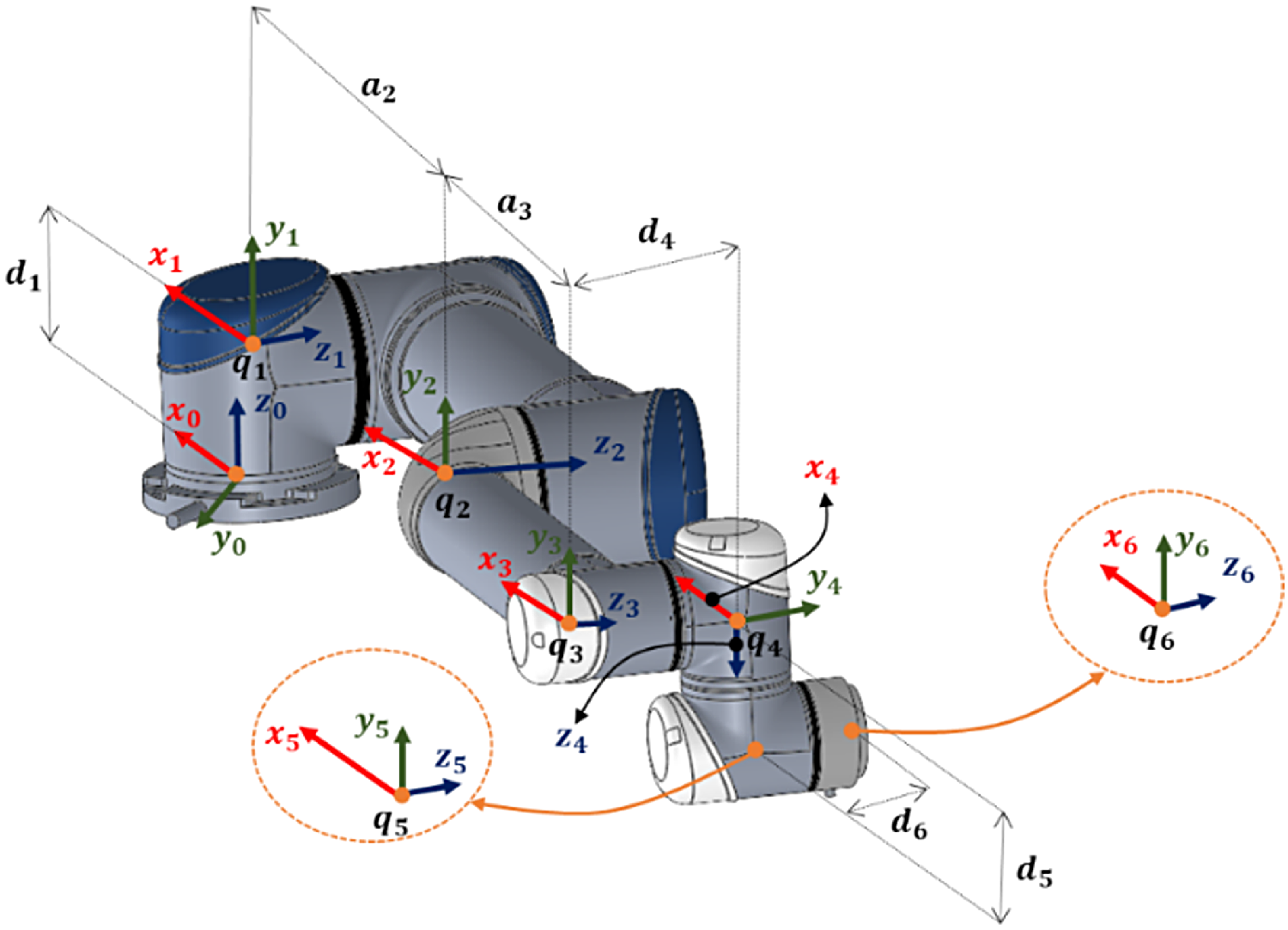
The UR5 robot manipulator has 6 DOF in a serial-link configuration. Figure 1 meticulously details the coordinate frame assignment for each joint of the UR5 manipulator, accompanied by the corresponding Denavit-Hartenberg (DH) parameters.
Axes placements with Denavit-Hartenberg convention of the of UR5.

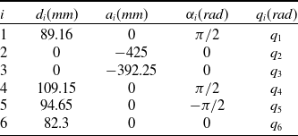
The DH convention is used to obtain the best-known forward kinematic model of the UR5, and the DH parameters for the UR5 are listed in Table I, corresponding to the joint axes shown in Figure 1.
Results of overloading for three experimental setups.

The kinematics of an industrial robot is detailed in [Reference Ayiz and Kucuk33]. In Table I,
 $i$
denotes the joint number,
 $d$
denotes the link offset,
 $a$
denotes the link length,
 $\alpha$
denotes the twist angle, and q denotes the joint rotation angle. The transformation matrices of 6 DOF UR5 are given in Eq. (1).
 \begin{align}_{6}^{0}{T}{} & ={}_{1}^{0}{T}{}_{2}^{1}{T}{}_{3}^{2}{T}{}_{4}^{3}{T}{}_{5}^{4}{T}{}_{6}^{5}{T}{}\nonumber\\[5pt]_{6}^{0}{T}{} & =\left[\begin{array}{cccc} cosq_{1} & 0 & sinq_{1} & 0\\[3pt]sinq_{1} & 0 & -cosq_{1} & 0\\[3pt]0 & 1 & 0 & d_{1}\\[3pt] 0 & 0 & 0 & 1 \end{array}\right]\left[\begin{array}{cccc} cosq_{2} & -sinq_{2} & 0 & a_{2}cosq_{2}\\[3pt] sinq_{2} & cosq_{2} & 0 & a_{2}sinq_{2}\\[3pt]0 & 0 & 1 & 0\\[3pt] 0 & 0 & 0 & 1 \end{array}\right]\left[\begin{array}{cccc} cosq_{3} & -sinq_{3} & 0 & a_{3}cosq_{3}\\[3pt] sinq_{3} & cosq_{3} & 0 & a_{3}sinq_{3}\\[3pt]0 & 0 & 1 & 0\\[3pt]0 & 0 & 0 & 1 \end{array}\right]\ldots\nonumber\\[5pt]& \ldots \left[\begin{array}{cccc} cosq_{4} & 0 & sinq_{4} & 0\\[3pt]sinq_{4} & 0 & -cosq_{4} & 0\\[3pt]0 & 1 & 0 & d_{4}\\ [3pt]0 & 0 & 0 & 1 \end{array}\right]\left[\begin{array}{cccc} cosq_{5} & 0 & -sinq_{5} & 0\\[3pt]sinq_{5} & 0 & cosq_{5} & 0\\[3pt]0 & -1 & 0 & d_{5}\\[3pt]0 & 0 & 0 & 1 \end{array}\right]\left[\begin{array}{cccc} cosq_{6} & -sinq_{6} & 0 & 0\\[3pt]sinq_{6} & cosq_{6} & 0 & 0\\[3pt]0 & 0 & 1 & d_{5}\\[3pt]0 & 0 & 0 & 1 \end{array}\right]\end{align}
 $_{6}^{0}{T}{}$
contains the position and orientation of the UR5 in Cartesian task space. Upon performing matrix multiplication in Eq. (1), was arrived at Eq. (2). Eq. (2) is detailed in Appendix.
 \begin{equation}_{6}^{0}{T}{}=\left[\begin{array}{cccc} n_{x} & o_{x} & a_{x} & p_{x}\\[3pt]n_{y} & o_{y} & a_{y} & p_{y}\\[3pt]n_{z} & o_{z} & a_{z} & p_{z}\\ [3pt]0 & 0 & 0 & 1 \end{array}\right]\end{equation}
The model describing the dynamics of the robot manipulator systems is derived using the Lagrange-Euler or Newton-Euler method. These dynamic fundamental models define the relationship between the robot manipulator’s joint torques, positions, velocities, and accelerations. Central to the analysis of robot manipulator dynamics, Eq. (3) expresses the differential equations of motion for serial n-joint rigid bodies in a commonly used format. A detailed derivation of this equation is provided in reference [Reference Spong, Hutchinson and Vidyasagar34].
 \begin{equation}\tau =M\left(q\right)\ddot{q}+C\left(q,\dot{q}\right)\dot{q}+G\left(q\right)+\tau _{d}\left(q,\dot{q}\right)\end{equation}
The robot manipulator dynamics are governed by several factors, including the mass matrix (
 $M(q)\in \mathbb{R}^{n\times n}$
), the centripetal-Coriolis vector (
 $C(q,\dot{q})\in \mathbb{R}^{n\times n}$
), the gravity vector (
 $G(q)\in \mathbb{R}^{n}$
), and disturbances (
 $\tau _{d}(q,\dot{q})$
). The joint torques (
 $\tau \in \mathbb{R}^{n}$
) are determined by these factors and the desired joint positions (
 $q\in \mathbb{R}^{n}$
), velocities (
 $\dot{q}\in \mathbb{R}^{n}$
), and accelerations (
 $\ddot{q}\in \mathbb{R}^{n}$
). The Jacobian matrix serves to establish the connection between workspace force and joint space torque. Friction is a significant component of these disturbances and uncertainties, and a new friction model is proposed in [Reference Karahan and Karci35], taking into account the friction effects in the joints. Building upon Eq. (3), which expresses the robot manipulator dynamics as a combination of joint angular velocities and motor torques, controlling the actuators translates to achieving the desired tracking control. The angular acceleration (
 $\ddot{q}$
), can be obtained by multiplying both sides by
 $M^{-1}(q)$
.
 \begin{equation}\ddot{q}=M^{-1}\left(q\right)u(t)-M^{-1}\left(q\right) C\left(q,\dot{q}\right)\dot{q}-M^{-1}\left(q\right)G\left(q\right)-M^{-1}\left(q\right)\tau _{d}\left(q,\dot{q}\right)\end{equation}
In this equation
 $\tau$
is denoted as
 $u(t)$
. Existing friction models like the Coulomb-viscous and Stribeck-curve approaches play a vital role in characterizing friction for high-precision robot motion. However, these models may not fully capture all aspects of friction, particularly the hysteresis effect. To address this limitation, the Centro-Symmetric Friction Model (CSFM) has been proposed, providing a more comprehensive description of friction phenomena [Reference Karahan and Karci35]. The Coulomb-viscous model provides a fundamental framework for friction representation, the Stribeck-curve model describes the friction properties better, but the CSFM model reveals the hysteresis effect and joint friction more meaningfully. Therefore, it is suggested that the CSFM model be employed for identifying friction within robotic dynamics, as discussed in reference [Reference Karahan and Karci35]. The mathematical details of the CSFM equation can be as:
 \begin{equation}\tau _{d}\left(q,\dot{q}\right)=\begin{cases} \begin{array}{c} T_{v}^{+}\dot{q}+sign\left(\dot{q}\right)\left(T_{c}^{+}+\left(T_{s}^{-}-T_{c}^{+}\right)e^{{-\left| \frac{\dot{q}}{\dot{q}_{s}^{+}}\right| ^{{\delta ^{+}}}}}\right)\left(\dot{q}\geq 0, \ddot{q}\lt 0\right)\\T_{v}^{+}\dot{q}+sign\left(\dot{q}\right)\left(T_{c}^{+}+\left(-T_{s}^{-}-T_{c}^{+}\right)e^{{-\left| \frac{\dot{q}}{\dot{q}_{s}^{-}}\right| ^{{\delta ^{-}}}}}\right)\left(\dot{q}\geq 0, \ddot{q}\geq 0\right)\\T_{v}^{-}\dot{q}+sign\left(\dot{q}\right)\left(T_{c}^{-}+\left(T_{s}^{+}-T_{c}^{-}\right)e^{{-\left| \frac{\dot{q}}{\dot{q}_{s}^{+}}\right| ^{{\delta ^{+}}}}}\right)\left(\dot{q}\lt 0, \ddot{q}\geq 0\right) \end{array}\\T_{v}^{-}\dot{q}+sign\left(\dot{q}\right)\left(T_{c}^{-}+\left(-T_{s}^{-}-T_{c}^{-}\right)e^{{-\left| \frac{\dot{q}}{\dot{q}_{s}^{-}}\right| ^{{\delta ^{-}}}}}\right)(\dot{q}\lt 0, \ddot{q}\lt 0) \end{cases}\end{equation}
where
 $T_{v}$
,
 $T_{c}$
, and
 $T_{s}$
denote viscous, Coulomb, and static friction coefficient, respectively, and
 $\dot{q}_{s}$
,
 $\delta$
represent Stribeck velocity, shape factor, respectively. Leveraging the CSFM framework, the comprehensive robot dynamics model can be acquired by substituting Eq. (5) into Eq. (4).
3. Controllers’ design
This section delves into the design methodologies for a series of controllers, progressing from the PIDSMC to the more advanced FOFPIDSMC. All these controllers share the primary objective of achieving high tracking performance and stability for the end effector while leveraging the model-based nature of the SMC approach. Here, the controller design within SMC adapts based on the specific system dynamics. The design of SMC is based on the Lyapunov stability theorem, which ensures that the system maintains stability. SMC is also a robust controller that can handle plant model uncertainties without degrading performance. However, the biggest disadvantage of SMC is chattering. Chattering causes constant vibration, which makes the controller output oscillate in the full saturation range. This can cause wear and deterioration of the material structure.
Chattering, a well-known issue in classical SMC that utilizes PD surfaces, can be partially mitigated by incorporating an integral (I) term. However, it may not be entirely eliminated. To address this persistent challenge, the current research proposes a fractional fuzzy PID (FOFPID) sliding surface scheme, aiming to effectively suppress chattering and enhance controller robustness. This scheme combines fractional PID, FL PID, and a combination of the two.
The basic design of the PIDSMC is explained first, followed by its modifications for different controller configurations. These modifications are:
-
• FOPIDSMC, which replaces the integer integrator and differentiator with FO;
-
• FPIDSMC, which converts the PID structure to the fuzzy PID structure; and
-
• FOFPIDSMC, which replaces the fuzzy PID structure with the integer integrator and the differentiator with FO.
3.1. PIDSMC design
PIDSMC is a PID sliding surface SMC method that is used to select the sliding surface in order to increase the robustness and sensitivity of the SMC. The surface of PIDSMC is as follows:
 \begin{equation}\sigma \left(t\right)=K_{p}e\left(t\right)+K_{i}\int e(t)dt+K_{d}\frac{d}{dt}e(t)\end{equation}
where
 $K_{p}$
,
 $K_{i}$
and
 $K_{d}$
are the
 $6\times 6$
diagonal gain matrix for terms of proportional, integral, and derivative, respectively. The trajectory tracking position error is:
 \begin{equation}e\left(t\right)=q_{d}\left(t\right)-q_{a}(t)\end{equation}
where
 $q_{d}(t)$
and
 $q_{a}(t)$
represent the desired and actual angular positions of the manipulator’s end-points, respectively.
Typically, the design of the PIDSMC sliding surface is predicated upon the position error (
 $e)$
) and its velocity (
 $\dot{q}$
). The convergence of the sliding surface derivative,
 $\dot{\sigma }(t)\rightarrow 0$
, is a critical requirement for achieving stability in the sliding mode. This convergence, in turn, guarantees that the tracking error also approaches zero within the sliding mode. This means the system’s actual trajectory aligns with the desired trajectory, and only a steady-state control effort is required to maintain this alignment. The sliding surface
 $\sigma (t)$
is differentiated with respect to time from the equation:
 \begin{equation}\dot{\sigma }\left(t\right)=K_{p}\dot{e}\left(t\right)+K_{i}e(t)+K_{d}\ddot{e}(t)\end{equation}
By replacing
 $\ddot{e}(t)=\ddot{q}_{d}(t)-\ddot{q}_{a}(t)$
with the equality in Eq. (8), the primary derivative of
 $\sigma (t)$
is ascertained as:
 \begin{equation}\dot{\sigma }\left(t\right)=K_{p}\dot{e}\left(t\right)+K_{i}e(t)+K_{d}\left(\ddot{q}_{d}\left(t\right)-\ddot{q}_{a}(t)\right)\end{equation}
Substituting the angular acceleration from Eq. (4) into Eq. (9) for
 $\ddot{q}_{a}(t)$
Eq. (9) becomes as follows:
 \begin{align}\dot{\sigma }\left(t\right)&=K_{p}\dot{e}\left(t\right)+K_{i}e\left(t\right)+K_{d}\left(\ddot{q}_{d}\left(t\right)-M^{-1}\left(q\right)u\left(t\right)+M^{-1}\left(q\right) C\left(q,\dot{q}\right)\dot{q}+M^{-1}\left(q\right)G\left(q\right)\right.\nonumber\\& \quad\left. +M^{-1}\left(q\right)\tau _{d}\left(q,\dot{q}\right)\right)\end{align}
 $\dot{\sigma }(t)$
is adjusted to zero to obtain the equivalent control input
 $u_{eq}(t)$
given by the equation below:
 \begin{align}u_{eq}\left(t\right)&=\left(M^{-1}\left(q\right)\right)^{-1}\left(\ddot{q}_{d}\left(t\right)+M^{-1}\left(q\right) C\left(q,\dot{q}\right)\dot{q}+M^{-1}\left(q\right)G\left(q\right)+M^{-1}\left(q\right)\tau _{d}\left(q,\dot{q}\right)\right.\nonumber\\ &\quad\left. +\frac{K_{p}}{K_{d}}\dot{e}\left(t\right)+\frac{K_{i}}{K_{d}}e(t)\right)\end{align}
The reaching law, delineated in the preceding equation, constitutes a component of the SMC control principle. Its design is aimed at guaranteeing the stability of the closed-loop system. The output of the system is forced to follow the sliding surface with the help of the reaching law. There are commonly used reaching laws in the literature, such as exponential, fixed rate, and power rate rules [Reference Liu and Wang36]. Due to the structure of the SMC, chattering is an undesirable phenomenon that adversely affects the efficient operation of the controller. The control signal of the SMC becomes a discontinuous switching signal on the sliding surface, which produces chattering. To mitigate or eliminate chattering in SMC, a narrow boundary layer can be strategically designed around the switching surface. For this, saturation [Reference Liu, Liu, Meng and An37] or a more softened sigmoid function [Reference Ataşlar-Ayyıldız, Karahan and Yılmaz22] can be used instead of the sign function. In this research, the switching input
 $u_{sw}(t)$
is selected as a sigmoid function, as given below:
 \begin{equation}u_{sw}\left(t\right)=\omega \frac{{\sigma} \left(t\right)}{\left| {\sigma} \left(t\right)\right| +\gamma }\end{equation}
where
 $\gamma \gt 0$
is the boundary layer thickness and
 $\omega \gt 0$
is the coefficient that determines how fast the control signal arrives at the sliding surface along the reaching phase. The complete control rule of PIDSMC is the combination of the equivalent control
 $u_{eq}(t)$
and the reaching control
 $u_{sw}(t)$
, as given below:
 \begin{align}u_{\textit{PIDSMC}}\left(t\right)&=u_{eq}\left(t\right)+u_{sw}\left(t\right)=\left(M^{-1}\left(q\right)\right)^{-1}\left(\ddot{q}_{d}\left(t\right)+M^{-1}\left(q\right) C\left(q,\dot{q}\right)\dot{q}+M^{-1}\left(q\right)G\left(q\right)\right.\nonumber\\&\quad\left. +M^{-1}\left(q\right)\tau _{d}\left(q,\dot{q}\right)+\frac{K_{p}}{K_{d}}\dot{e}\left(t\right)+\frac{K_{i}}{K_{d}}e\left(t\right)+\omega \frac{{\sigma} \left(t\right)}{\left| {\sigma} \left(t\right)\right| +\gamma }\right)\end{align}
3.2. FOPIDSMC design
In contrast to conventional or intelligent controllers, this control technique draws upon fractional calculus. This mathematical framework offers a richer set of control design possibilities due to its inherent additional degrees of freedom. Leveraging fractional calculus, the proposed control strategy achieves enhanced closed-loop response and demonstrably robust closed-loop control performance, as corroborated by [Reference Ataşlar-Ayyıldız, Karahan and Yılmaz22].
Approaches such as Riemann-Liouville, Caputo, Grunwald-Letnikov, and Oustaloup are commonly used for fractional calculus analysis. Among fractional derivative definitions, the Riemann-Liouville approach enjoys the most widespread use. In the time domain, the integral and fractional derivative of
 $f(t)$
are given as [Reference Das38]:
 \begin{equation}{b}^{ }{D}{}_{t}^{\alpha }f\left(t\right)=\frac{1}{P\left(\varepsilon -\alpha \right)}\frac{d^{\varepsilon }}{dt^{\varepsilon }}\int _{b}^{t}\frac{f\left(\tau \right)}{\left(t-\tau \right)^{\alpha -\varepsilon +1}}d\tau\end{equation}
where
 $\varepsilon -1\lt \alpha \lt \varepsilon, \varepsilon \in \mathbb{N}, \alpha \in \mathbb{R}^{+}$
and the well-recognized Euler’s Gamma function is denoted by
 $P(\cdot )$
as follows:
 \begin{equation}P\left(x\right)=\int _{0}^{\mathrm{\infty }}t^{x-1}e^{-t}dt,\mathbb{R}\left(x\right)\gt 0\end{equation}
The fractional integral operator and the fractional derivative operator from the Riemann-Liouville definition are given by
 ${b}^{ }{D}{}_{t}^{-\lambda }f(t)$
and
 ${b}^{ }{D}{}_{t}^{\mu }f(t)$
, respectively, where
 $\lambda$
and
 $\mu$
positive real numbers. To simplify the expression, replace
 ${b}^{ }{D}{}_{t}^{-\lambda }f(t)$
and
 ${b}^{ }{D}{}_{t}^{\mu }f(t)$
with
 $D^{-\lambda }$
and
 $D^{\mu }$
.
Researchers have recently preferred to use fractional calculus to enhance the productivity and robustness of the PID controller, which is widely used in many systems. To do this, they have developed the FO PID (FOPID) controller, which is demonstrated as
 $PI^{\lambda }D^{\mu }$
, where
 $\lambda$
and
 $\mu$
correspond to the integral and derivative FOs, respectively. The differential form of the
 $PI^{\lambda }D^{\mu }$
controller is expressed as:
 \begin{equation}\sigma \left(t\right)=K_{p}e\left(t\right)+K_{i}D_{t}^{-\lambda }e\left(t\right)+K_{d}D_{t}^{\mu }e\left(t\right)\end{equation}
The FOPID structure given above is selected as the sliding surface in the SMC [Reference Kumar, Azar, Kumar and Rana30]. A vanishing second-order derivative of the sliding surface (
 $\ddot{\sigma }(t)\rightarrow 0$
) implies convergence of both error and its derivate (velocity) within the sliding mode. This additional constraint usually leads to faster reaching to the sliding mode compared to PIDSMC, resulting in quicker tracking of the desired trajectory. Differentiating Eq. (16) twice:
 \begin{equation}\ddot{\sigma }\left(t\right)=K_{p}\ddot{e}\left(t\right)+K_{i}D_{t}^{-\lambda +2}e\left(t\right)+K_{d}D_{t}^{\mu +2}e(t)\end{equation}
Substituting
 $\ddot{e}(t)=\ddot{q}_{d}(t)-\ddot{q}_{a}(t)$
into Eq. (17):
 \begin{equation}\ddot{\sigma }\left(t\right)=K_{p}\left(\ddot{q}_{d}\left(t\right)-\ddot{q}_{a}(t)\right)+K_{i}D_{t}^{-\lambda +2}e\left(t\right)+K_{d}D_{t}^{\mu +2}e(t)\end{equation}
Substituting the angular acceleration expressed by Eq. (4) for
 $\ddot{q}_{a}(t)$
in Eq. (18) yields the following:
 \begin{align}\ddot{\sigma }\left(t\right)&=K_{p}\left(\ddot{q}_{d}\left(t\right)-M^{-1}\left(q\right)\tau +M^{-1}\left(q\right) C\left(q,\dot{q}\right)\dot{q}+M^{-1}\left(q\right)G\left(q\right)+M^{-1}\left(q\right)\tau _{d}\left(q,\dot{q}\right)\right)\nonumber\\&\quad +K_{i}D_{t}^{-\lambda +2}e\left(t\right)+K_{d}D_{t}^{\mu +2}e(t)\end{align}
Setting
 $\ddot{\sigma }(t)=0$
to achieve the sliding mode condition allows us to obtain the equivalent control input,
 $u_{eq}(t)$
:
 \begin{align}u_{eq}\left(t\right)&=\left(M^{-1}\left(q\right)\right)^{-1}\left(\ddot{q}_{d}\left(t\right)+M^{-1}\left(q\right) C\left(q,\dot{q}\right)\dot{q}+M^{-1}\left(q\right)G\left(q\right)+M^{-1}\left(q\right)\tau _{d}\left(q,\dot{q}\right)\right.\nonumber\\&\quad\left. +\frac{K_{d}}{K_{p}}D_{t}^{\mu +2}e(t)+\frac{K_{i}}{K_{p}}D_{t}^{-\lambda +2}e\left(t\right)\right)\end{align}
The sigmoid function in Eq. (12) is selected as the switching law, as in the PIDSMC controller, and combined with Eq. (20) to obtain the total control signal for FOPIDSMC.
 \begin{equation*} u_{\textit{FOPIDSMC}}\left(t\right)=u_{eq}\left(t\right)+u_{sw}\left(t\right) \end{equation*}
 \begin{align}&=\left(M^{-1}\left(q\right)\right)^{-1}\left(\ddot{q}_{d}\left(t\right)+M^{-1}\left(q\right) C\left(q,\dot{q}\right)\dot{q}+M^{-1}\left(q\right)G\left(q\right)+M^{-1}\left(q\right)\tau _{d}\left(q,\dot{q}\right)+\frac{K_{d}}{K_{p}}D_{t}^{\mu +2}e\left(t\right)\right.\nonumber\\&\quad\left. +\frac{K_{i}}{K_{p}}D_{t}^{-\lambda +2}e\left(t\right)+\omega \frac{{\sigma} \left(t\right)}{\left| {\sigma} \left(t\right)\right| +\gamma }\right)\end{align}
Thus, the FO PID surface effect is also included in the newly designed SMC-based controller.
3.3. FPIDSMC design
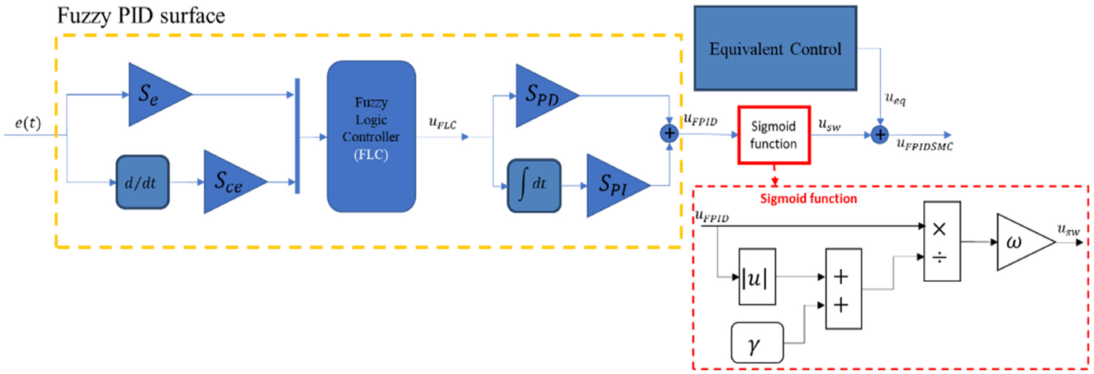
FL is particularly effective at overcoming the challenges of nonlinear system modeling and control and has therefore been widely adopted in control engineering applications. Just like conventional controllers, fuzzy controllers can be designed as Fuzzy PD, Fuzzy PI, Fuzzy PID, or a combination of these. FL integration with PID control has gained traction recently due to its demonstrated effectiveness in handling the intricacies of nonlinear and complex dynamic systems. Fuzzy PID controllers combine fuzzy PD and PI elements, with gains acting as scaling factors [Reference Woo, Chung and Lin39–Reference Yesil, Güzelkaya and Eksin40]. By choosing the fuzzy PID on the sliding surface of the SMC, the performance of the SMC increases with the adaptive coefficients in the fuzzy structure, together with the robustness and insensitivity to external effects. Based on this, a unification of Fuzzy–PD, and Fuzzy–PI controllers presented in [Reference Ataşlar-Ayyıldız and Karahan41] is conferred to design a Fuzzy PID surface. As depicted in Figure 2, the proposed controller integrates an FLC with an SMC scheme. The FLC processes error signals and their derivatives (inputs), and its output is combined with an integral term. This combined signal, after scaling with appropriate coefficients, forms the sliding surface output for the SMC. It’s important to note that this design employs integer-order derivatives and integrals. The signal from the equivalent control and the signal from the SMC are summed together to obtain the total control signal.
Detailed configuration of the FPIDSMC.

As depicted in Figure 2, the FLC unit’s output is determined by the error signal and its derivative. This function is given by:
 \begin{equation}u_{FLC}\left(t\right)=f(S_{e}e\left(t\right),S_{ce}de(t)/dt)\end{equation}
Eq. (22) defines scaling factors
 $S_{e}$
and
 $S_{ce}$
, responsible for mapping linguistic variables across the discourse universe and scaling the FLC’s error and derivative of error inputs. Both the FLC output and its integral undergo normalization across the universe of discourse using the
 $S_{PI}$
and
 $S_{PD}$
scaling factors.
The output value of the FLC and the integral of the output are normalized across the universe of discourse with the
 $S_{PI}$
and
 $S_{PD}$
scaling factors. The representation of the fuzzy function is expressed by the nonlinear input-output mapping
 $f$
function. Consequently, the expression for the SMC sliding surface becomes the following equation [Reference Ataşlar-Ayyıldız and Karahan41].
 \begin{equation}u_{FPID}\left(t\right)=S_{PD}u_{FLC}\left(t\right)+S_{PI}d^{-1}u_{FLC}(t)/dt^{-1}\end{equation}
The total control signal
 $u_{\textit{FPIDSMC}}(t)$
is obtained by combining the equivalent control
 $u_{eq}(t)$
with the sigmoid function signals, as shown in Eq. (24).
 \begin{equation}u_{\textit{FPIDSMC}}\left(t\right)=\omega \frac{u_{FPID}\left(t\right)}{\left| u_{FPID}\left(t\right)\right| +\gamma }+u_{eq}\left(t\right)\end{equation}
Information about how to obtain
 $u_{eq}(t)$
and the values of
 $\omega$
and
 $\gamma$
given in the PIDSMC design.
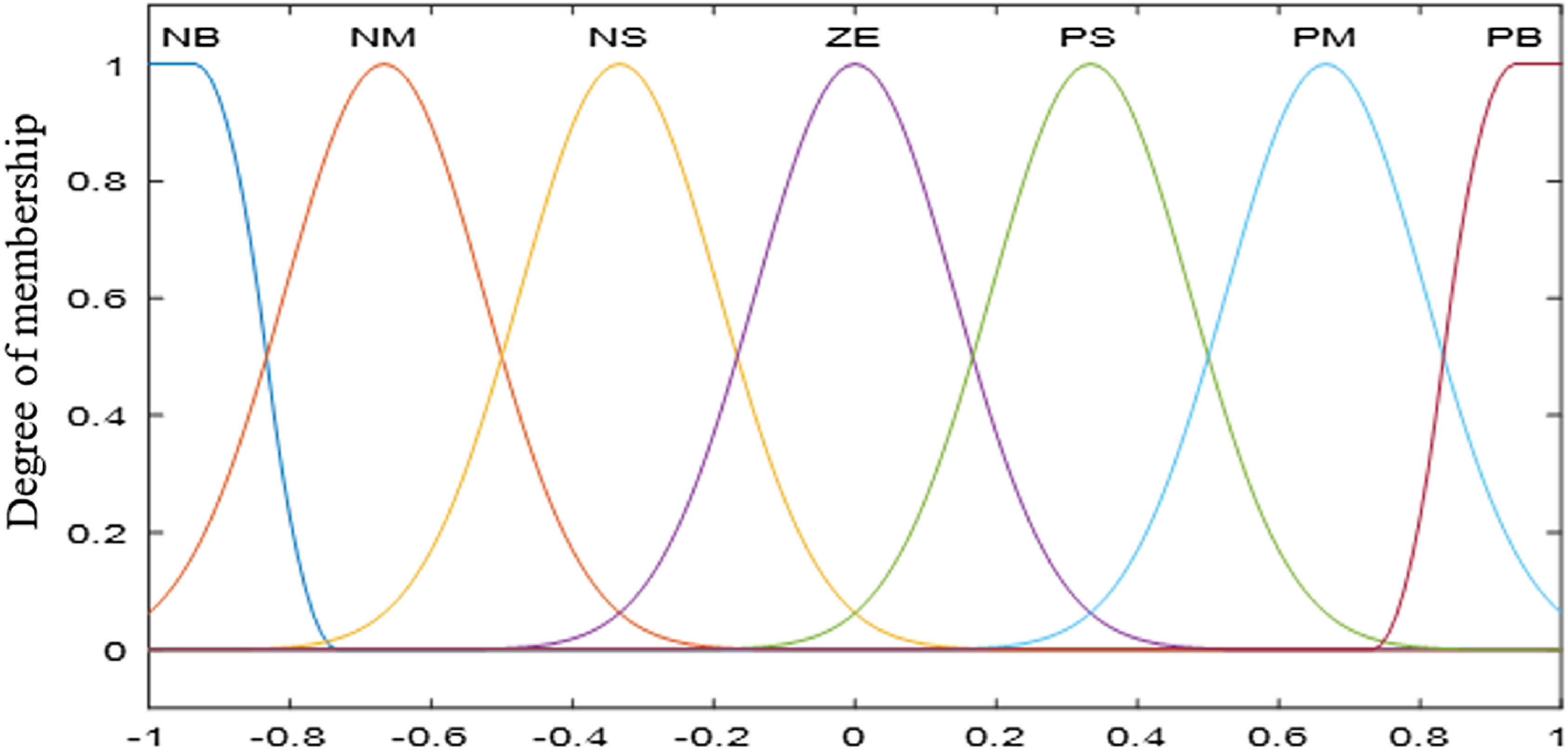
The FL internal structure of FPIDSMC control uses seven membership functions to represent input and output signals, as indicated in Figure 3. PB and NB are Z-shape membership functions, while the others (NM, NS, ZE, PS, PM) are Gaussian membership functions. The range of membership functions is defined to be [-1, 1] for both inputs and outputs.
Input/output fuzzy membership functions.

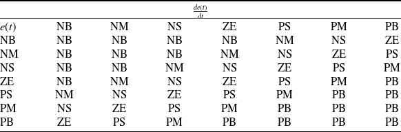
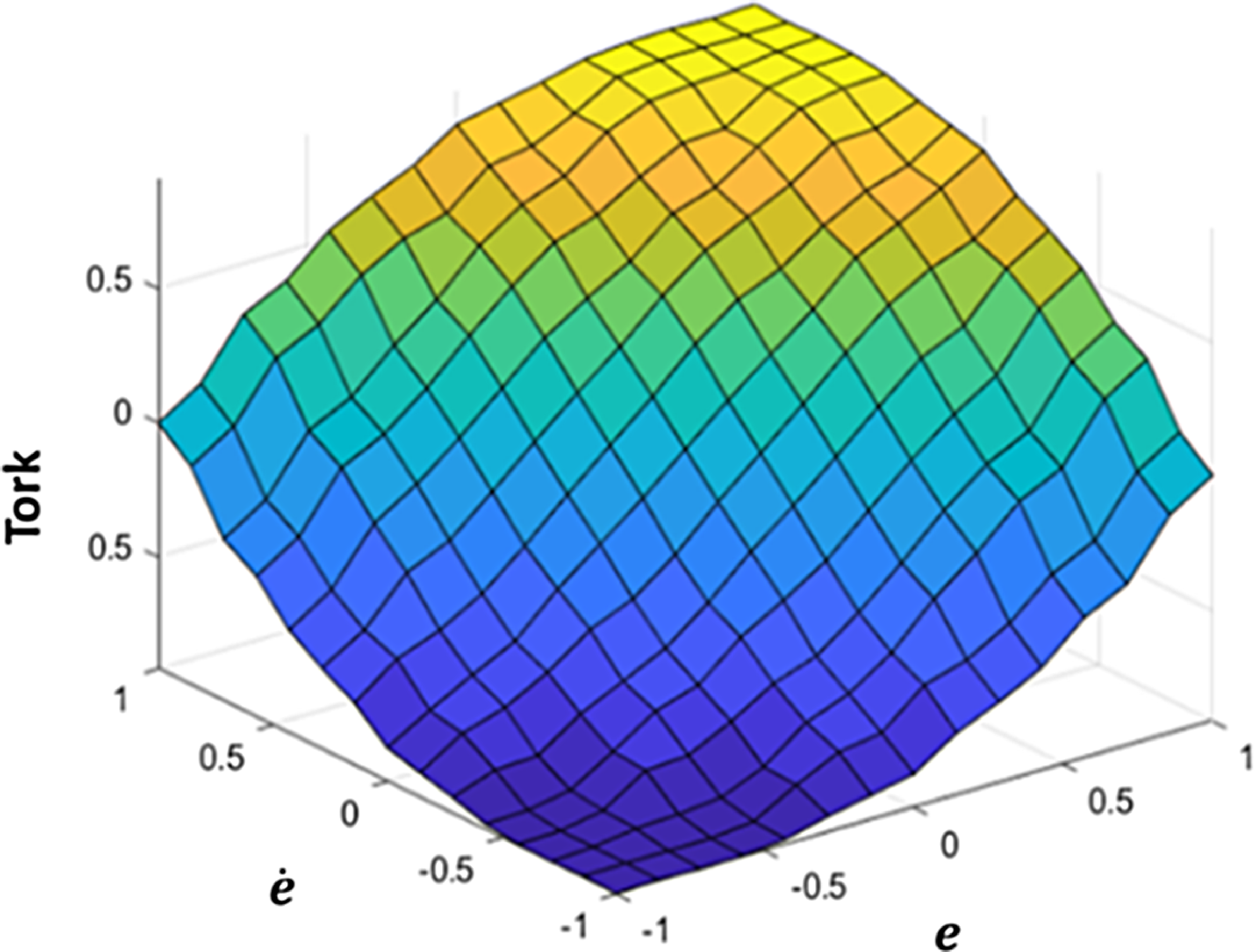
In line with the chosen FL framework, this study employs the Standard Mac Vicar-Whelan Rule Table in [Reference MacVicar-Whelan42]. This rule table, detailed in Table II, defines the FLC’s decision-making logic. As depicted in Figure 4, the corresponding fuzzy control surface provides a visual representation of the rule base. Notably, the rule table exhibits a gradual increase from NB to PB for both inputs and outputs.
Fuzzy rule table.

Visualization of fuzzy inference surface.

3.4. FOFPIDSMC design
In contrast to the integer-order derivative and integral terms employed in FPIDSMC, the proposed FFPIDSMC introduces the concept of FO control. Fractional parameters μ and λ represent the derivative and integral components.
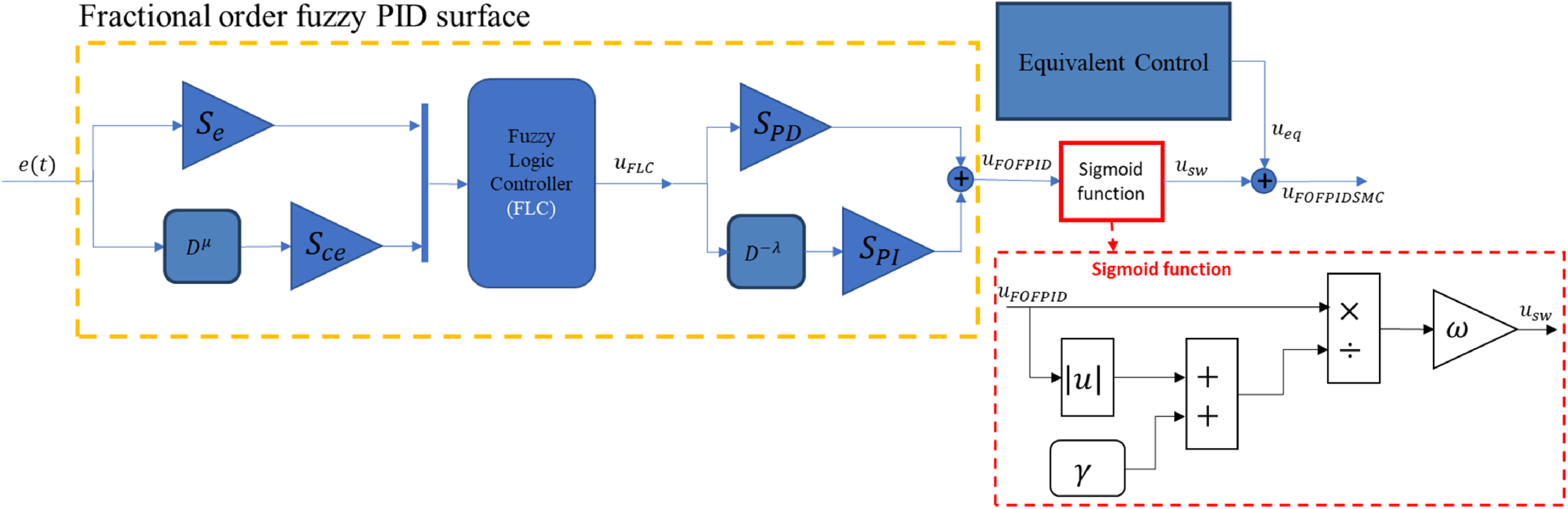
The proposed FOFPID controller is chosen as the sliding surface of the SMC. FOFPIDSMC has been proposed to combine the advantages of the FO PID’s parameter space with the adaptive parameter advantages of FL to increase the efficiency of the SMC. The detailed configuration of FOFPIDSMC is shown in Figure 5.
Elaborate form of the fractional order fuzzy PID sliding mode control.

The surface view with the fuzzy rule table and input-output membership functions used in FOFPIDSMC is presented in the previous section, as for FPIDSMC.
3.5. Stability analysis using Lyapunov criteria
The stability analysis of the sliding mode controller relies on the Lyapunov stability theorem. In this study, to utilize a positive definite Lyapunov function defined as:
 \begin{equation}\mathrm{V}\left(t\right)=\frac{1}{2}\sigma ^{2}(t)\end{equation}
In order for the asymptotic stability condition to be performed in the Lyapunov function, it must be positive (
 $\mathrm{V}(t)\gt 0$
) and its derivative must be negative (
 $\dot{\mathrm{V}}(t)\lt 0$
) at the balance point at the origin
 $\sigma (t)=0$
.
The expression for the time derivative of the Lyapunov function,
 $\dot{\mathrm{V}}(t)$
, defined in Eq. (25), is:
 \begin{equation}\dot{\mathrm{V}}\left(t\right)=\sigma \left(t\right)\dot{\sigma }\left(t\right)=-\omega \frac{\sigma ^{2}\left(t\right)}{\left| \sigma \left(t\right)\right| +\gamma }\lt 0\end{equation}
the system conditions allow the sliding surface
 $\sigma (t)=0$
to be reached and maintained.
4. Controller parameters optimization
To acquire the desired control performance, the controller parameters must be optimized using a suitable objective function. This study utilizes the GWO-PSO algorithm to perform the optimization of controller parameters, aiming to minimize the objective function defined in Eq. (27).
 \begin{equation}f_{obj}=\frac{1}{nT}\sqrt{\sum _{t=1}^{T}\sum _{i=1}^{n}\left| {q_{d}}_{t,i}-{q_{a}}_{t,i}\right| ^{2}}\rightarrow min\end{equation}
where
 $n$
,
 $T$
,
 ${q_{d}}_{t,i}$
, and
 ${q_{a}}_{t,i}$
express the total number of joints of the robot, the size of the data, the reference trajectory, and the trajectory realized by the robot, respectively.
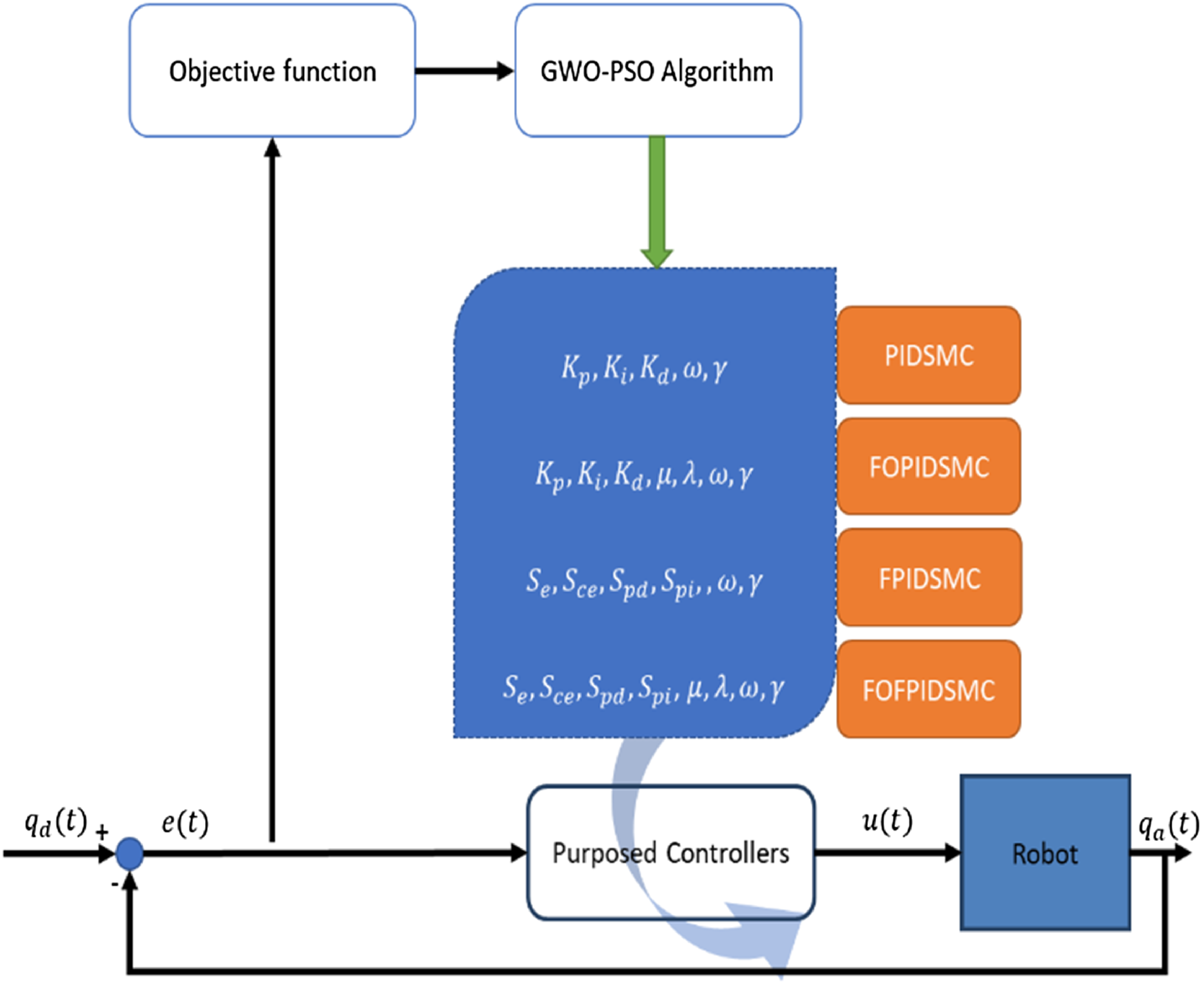
As depicted in Figure 6, the general methodology leverages the GWO-PSO algorithm for optimizing the controller parameters of the robot manipulator. This optimization process seeks to identify a set of parameters that achieve the desired response characteristics, while also improving the decisiveness of the controlled output power.
Block diagram depicting the proposed control algorithm.

In this study, the GWO-PSO-based controller parameters tuning algorithm yields the following optimal controller parameters: PIDSMC (
 $K_{p}, K_{i}, K_{d}, \omega, \gamma$
), FOPIDSMC (
 $K_{p}, K_{i}, K_{d},\mu, \lambda, \omega, \gamma$
), FPIDSMC (
 $S_{e}, S_{ce}, S_{pd}, S_{pi}, \omega, \gamma$
), and FOFPIDSMC (
 $S_{e}, S_{ce}, S_{pd}, S_{pi}, \mu, \lambda, \omega, \gamma$
). Leveraging insights from the literature review, the optimization transaction utilizes the following search ranges for the controller parameters:
 $K_{p}\in [0,1000]$
,
 $K_{i}\in [0,20]$
,
 $K_{d}\in [0,200]$
,
 $\{\omega, \gamma \}\in [0,50]$
,
 $\{\mu, \lambda \}\in [0,1]$
,
 $\{S_{e},S_{pi}\}\in [0,50]$
, and
 $\{S_{ce}, S_{pd}\}\in [0,20]$
. In addition to all these, since the focus is on comparing FOFPIDSMC with existing PIDSMC, FOPIDSMC, and FPIDSMC methods, the membership function parameters of FL are not included in the optimization and are used uniformly distributed as given in ref. [Reference Ataşlar-Ayyıldız and Karahan41].
4.1. Particle Swarm Optimization (PSO) algorithm
This study leverages PSO, a population-based metaheuristic optimization technique improved by Kennedy and Eberhart [Reference Kennedy and Eberhart43] in 1995. Inspired by the collective foraging attitude of bird and fish flocks, PSO is well-suited for optimizing controller parameters. In PSO, a randomly initialized swarm of particles explores the search space, with each particle’s position influenced by its own past experience and the best positions encountered by its neighbors.
Based on this, the top position of every particle and the top position of the particle swarm are stored for later use. In each PSO iteration, the following equations are used to renovate the position and velocity of each particle within the swarm.
 \begin{equation}p_{t+1}^{j}=p_{t}^{j}+v_{t+1}^{j}\end{equation}
 \begin{equation}v_{t+1}^{j}=\psi \left(\omega _{t}v_{t}^{j}+\zeta _{1}r_{1}\left[p_{t}^{p}-p_{t}^{j}\right]+\zeta _{2}r_{2}\left[p_{t}^{g}-p_{t}^{j}\right]\right)\end{equation}
In the above equations,
 $t$
represents the iteration number,
 $p_{t}^{j}$
and
 $v_{t}^{j}$
are the position and velocity of the
 $j^{th}$
particle at iteration
 $t$
,
 $\psi$
denotes the contraction factor,
 $\omega _{t}$
serves as the inertia weighting factor influencing the swarm’s searching prowess,
 $\zeta _{1}$
and
 $\zeta _{2}$
are the coefficients for learning, and
 $r_{1}$
and
 $r_{2}$
are uniformly distributed values between 0 and 1. Additionally,
 $v_{t+1}^{j}$
(particle
 $j$
’s velocity at
 $t+1$
),
 $p_{t+1}^{j}$
(particle
 $j$
’s position at
 $t+1$
),
 $p_{t}^{p}$
(particle
 $j$
’s personal best position at
 $t$
), and
 $p_{t}^{g}$
(global best position at
 $t$
).
4.2. Gray Wolf Optimization (GWO) algorithm
In addition to PSO, the GWO algorithm is utilized for optimization in this work. Proposed by Mirjalili et al. [Reference Mirjalili, Mirjalili and Lewis44], GWO mimics the social hierarchy and hunting behavior of gray wolves. This algorithm incorporates four main wolf types: alpha, beta, delta, and omega. These wolves play distinct roles within the pack, with the alpha acting as the leader, beta wolves providing support, delta wolves fulfilling subordinate roles, and omega wolves occupying the lowest rank.
The mathematical model presented below, inspired by the hunting attitude of gray wolves [Reference Mirjalili, Mirjalili and Lewis44], focuses on the encircling maneuver. This initial stage involves the wolves surrounding the victim, laying the groundwork for the subsequent stages of the hunt.
 \begin{equation}\vec {D}=\left| \vec {C}.\vec {X}_{P}\left(t\right)-\vec {X}(t)\right|\end{equation}
 \begin{equation}\vec {X}\left(t+1\right)=\vec {X}_{P}\left(t\right)-\vec {A}.\vec {D}\end{equation}
In the above equations,
 $t$
handles the current iteration. Additionally,
 $\vec {X}_{P}$
denotes the position of the prey (victim) in the search domain, while
 $\vec {X}_{P}$
represents the positions of individual wolves within the pack. Furthermore,
 $\vec {A}$
and
 $\vec {C}$
are coefficient vectors that influence the hunting behavior and are calculated as follows:
 \begin{equation}\vec {A}=\vec {a}.(2.\vec {r}_{1}-1)\end{equation}
 \begin{equation}\vec {C}=2.\vec {r}_{2}\end{equation}
where
 $\vec {r}_{1}$
and
 $\vec {r}_{2}$
symbolize random vectors uniformly distributed within the range [0, 1]. These random vectors introduce an element of stochasticity into the search process, mimicking the unpredictable nature of hunting behavior. Additionally,
 $\vec {a}$
signifies a linearly decreasing coefficient vector which starts at a value of 2 and gradually reduces to 0 over iterations, calculated as shown below:
 \begin{equation}\vec {a}(t)=2-2t/T\end{equation}
In the context of the GWO algorithm’s optimization process, the following equations model the core hunting strategy inspired by gray wolves. Alpha wolves demonstrate the solution with the best fitness value (best solution), while beta and delta wolves correspond to the second and third-best solutions, respectively. The remaining “wolves” (particles) utilize these leading positions to guide their own movements within the search space, ultimately leading toward optimal solutions.
 \begin{equation}\vec {D}_{\propto }=\left| \vec {C}_{1}.\vec {X}_{\propto }-\vec {X}(t)\right|, \vec {D}_{\beta }=\left| \vec {C}_{2}.\vec {X}_{\beta }-\vec {X}(t)\right|, \vec {D}_{\delta }=\left| \vec {C}_{3}.\vec {X}_{\delta }-\vec {X}(t)\right|\end{equation}
 \begin{equation}\vec {X}_{1}=\left| \vec {X}_{\alpha }-\vec {a}_{1}\vec {D}_{\alpha }\right|, \vec {X}_{2}=\left| \vec {X}_{\beta }-\vec {a}_{2}\vec {D}_{\beta }\right|, \vec {X}_{3}=\left| \vec {X}_{\delta }-\vec {a}_{3}\vec {D}_{\delta }\right|\end{equation}
 \begin{equation}\vec {X}_{P}\left(t+1\right)=\left(\vec {X}_{1}+\vec {X}_{2}+\vec {X}_{3}\right)/3\end{equation}
In these equations of hunting strategy,
 $\vec {C}_{1}$
,
 $\vec {C}_{2}$
,
 $\vec {C}_{3}$
,
 $\vec {a}_{1}$
,
 $\vec {a}_{2}$
,
 $\vec {a}_{3}$
express random vectors.
 $\vec {X}_{\alpha }$
,
 $\vec {X}_{\beta }$
and
 $\vec {X}_{\delta }$
indicate the location of alpha, beta and delta, respectively.
 $\vec {X}_{1}$
,
 $\vec {X}_{2}$
, and
 $\vec {X}_{3}$
determine the notional status of alpha, beta and delta, respectively.
 $\vec {X}_{P}(t+1)$
is defined as the new position of the victim.
4.3. Hybrid algorithm based on GWO and PSO
Metaheuristic methods are used to solve problems by searching for the best solution, which can be either local or global. While metaheuristic techniques do not assure the global optimum, they can maintain accomplished solutions to complex problems in a relatively simple and efficient manner [Reference Nazari-Heris, Mohammadi-Ivatloo and Gharehpetian45]. Researchers sometimes hybridize metaheuristics to improve their search capabilities and combine their advantages [Reference Ting, Yang, Cheng, Huang and Yang46]. Based on all these explanations, exploitation, and exploration capabilities are important locally and globally [Reference Devarapalli, Bhattacharyya and Sinha47]. The PSO algorithm’s established success in diverse optimization problems stems from its minimal parameter requirements and rapid convergence rate, as demonstrated in [Reference Ting, Yang, Cheng, Huang and Yang46]. This well-proven effectiveness across various fields makes it a compelling choice for inclusion in this hybrid optimization study. It is noteworthy that the GWO algorithm has a very high exploitation ability (local optimum success) but a weak exploration ability (global optimum) [Reference Karahan and Karci35]. However, effective optimization requires a balance between exploration and exploitation. While exploration allows for diverse exploration of the search space, exploitation focuses on refining solutions within promising regions, as emphasized in ref. [Reference Ting, Yang, Cheng, Huang and Yang46]. To increase this disadvantage of GWO, the PSO algorithm is implemented to update the positions of search agents within the GWO algorithm by hybridizing it with the well-known PSO algorithm. Thus, instead of searching agents going to a random location, which causes them to get stuck in local minima in GWO, it is aimed to find global minima by using the discovery feature of PSO.
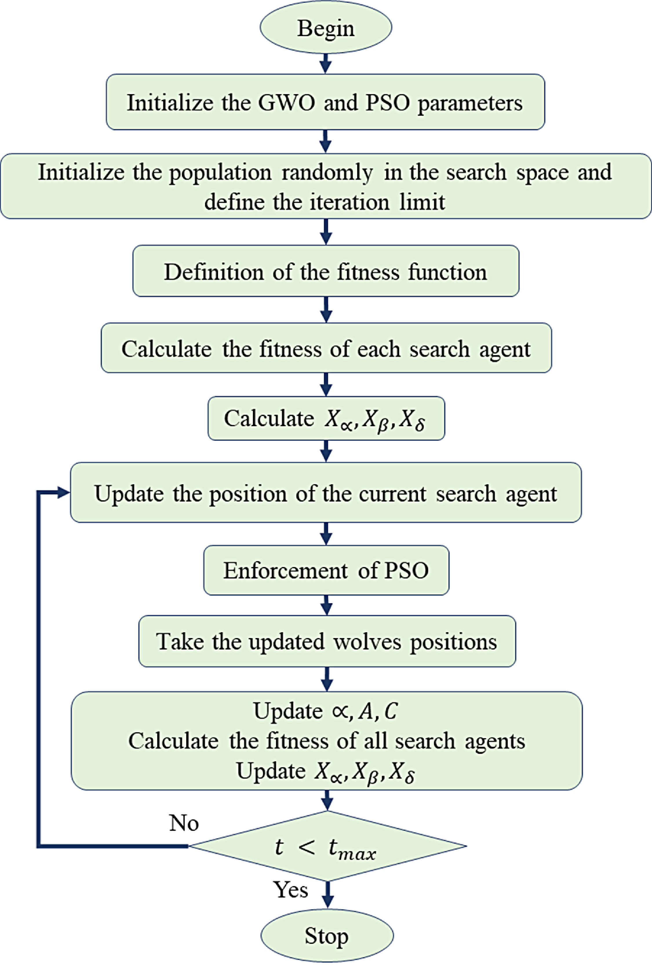
Hybridization has been proposed to address the disadvantages and combine the superiorities of the GWO and PSO algorithms by utilizing the GWO’s exploitation capability and the PSO’s exploration capability [Reference Karahan and Karci35, Reference Zhang, Lin, Mao, Liu, Dou and Liu48–Reference Gupta and Deep51]. Thus, the fundamental process steps of the Hybrid GWO-PSO technique, which is a new idea, are detailed in ref. [Reference Shaheen, Hasanien and Alkuhayli52]. According to this, the key steps involve initializing search agents, updating positions using GWO, identifying the best agents, switching to PSO, and iteratively refining the solution. The approach aims to achieve optimal results while ensuring stability. The technique is visually depicted in Figure 7.
Hybrid gray wolf optimization and particle swarm optimization algorithm flowchart.

To provide a clearer understanding of the hybridization process depicted in Figure 7, the algorithm integrates the GWO and PSO mechanisms as follows: Initially, the search agents’ positions are updated using the GWO algorithm’s hierarchical leadership structure, where alpha, beta, and delta wolves guide the rest of the agents toward promising regions based on their exploitation capability. After this stage, the top-performing agents identified by the GWO are further refined using the PSO algorithm’s velocity and position update rules.
Specifically, the PSO algorithm introduces an exploration mechanism by updating the positions of selected agents according to their previous velocities, their best-known positions (personal best), and the global best position achieved so far. This dual mechanism ensures that the search agents do not stagnate in local optima, as the PSO introduces a stochastic component to encourage diverse exploration of the search space. The iterative process alternates between GWO and PSO updates, leveraging the complementary strengths of both algorithms to balance exploitation and exploration effectively.
This detailed step-by-step integration is visually summarized in Figure 7 to illustrate the dynamic interaction between the two algorithms in the hybrid framework.
In this study, the number of agents for all algorithms used in the optimization process is set to 30, the number of iterations is set to 100, and the number of runs is set to 10. The PSO algorithm’s inertia weighting factor (
 $\omega$
) is set to 0.8, the contraction factor (
 $\psi$
) is set to 0.6, the learning factors (
 $\zeta _{1}$
,
 $\zeta _{2}$
) are set to 2, and the coefficients (
 $r_{1}$
and
 $r_{2}$
) are randomly chosen in the range
 $[0,1]$
. The GWO algorithm’s coefficients (
 $\vec {r}_{1}$
and
 $\vec {r}_{2}$
) are randomly selected in the range
 $[0,1]$
and the linear vector (
 $\vec {a}$
) decreases from 2 to 0 in each iteration.
5. Simulation results and discussions
This section delves into a comprehensive performance analysis of PIDSMC, FOPIDSMC, FPIDSMC, and FOFPIDSMC controllers tuned using the GWO-PSO algorithm for the 6-revolute universal robots 5 (6R UR5) robot manipulator system. The analysis focuses on three key aspects: handling disturbances (disturbance rejection), trajectory various tracking, and parametric model uncertainty management capabilities. To evaluate these aspects, a series of category-based studies are conducted on all controller types, providing a holistic assessment of their performance.
The development of the PSO-GWO algorithm, the design of the targeted controllers (PIDSMC, FOPIDSMC, FPIDSMC, and FOFPIDSMC), their adaptation to the 6R UR5 robot manipulator control system, and all subsequent simulations were conducted within the MATLAB/Simulink software platform. Notably, a sampling time of
 $1\,ms$
was employed for all experimental simulations. The results and comparative analyses of these simulations are presented and debated in the next subsections.
5.1. Dynamic performance analysis
Transient and steady-state responses for the 6R UR5 robot manipulator system controlled by PIDSMC, FOPIDSMC, FPIDSMC, and FOFPIDSMC are analyzed based on the objective function given in Eq. (27) while the reference input is a unit step. The optimal controller parameters are acquired by handling the objective function presented in Eq. (27) and optimizing it with GWO-PSO.
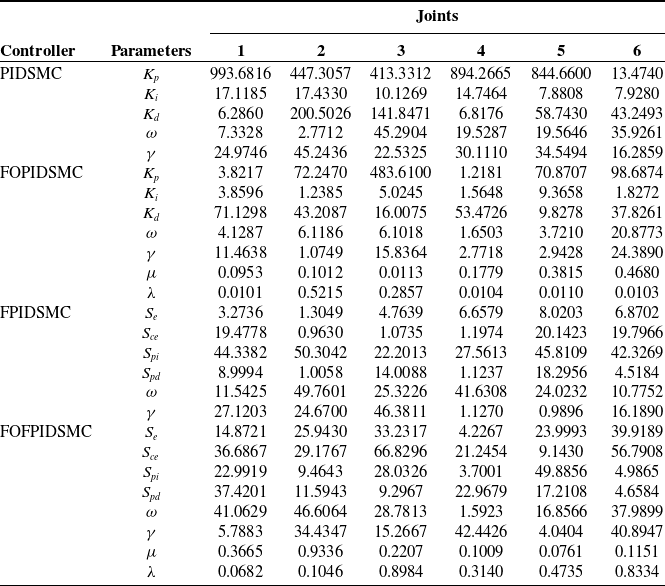
As a consequence, all simulations are conducted using GWO-PSO-based optimization for different scenarios with optimized controllers, as the parameter values of all joints of UR5 of each controller are indicated in Table III. The optimization is run 10 times for each controller, and the results are averaged to obtain the parameter values indicated in Table III.
Optimal controller parameters for 6R UR5 robot manipulator.

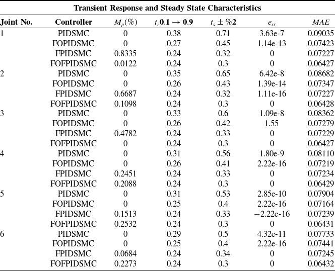
Dynamic response comparison of controllers for the 6R UR5 robot manipulator system.

The dynamic responses of the optimized controllers for all joints in terms of rise time (
 $t_{r}$
), settling time (
 $t_{s}$
), overshoot (
 $M_{p}$
), and state error (
 $e_{ss}$
) stability are given in Table IV. Additionally, in this table, the mean absolute error (MAE) criterion given in Eq. (38) has been used as the objective function to evaluate the dynamic performance.
 \begin{equation}e_{{MAE_{i}}}=\frac{1}{T}\sum _{t=1}^{T}\left| e_{i}(t)\right|\end{equation}
where
 $e_{i}(t)$
is the trajectory error of
 $t$
th sample of
 $i$
th joint and
 $T$
the number of sample.
As can be seen from Table IV, it can be concluded that the proffered GWO-PSO-based FOFPIDSMC with parameter tuning exhibits superior dynamic performance with the quickest settling time, minimal steady-state error, and MAE values for all joints of the robot. If evaluated in terms of rise times, it seems that FPIDSMC and FOFPIDSMC controllers give the lowest values than other controllers for all joints. In addition to these analyses, it is observed that although the percentage over-shot values of FL PIDSMC are higher than non-FL PIDSMC, FL PIDSMC performs better than other controllers in terms of transient dynamic responses according to other performance.
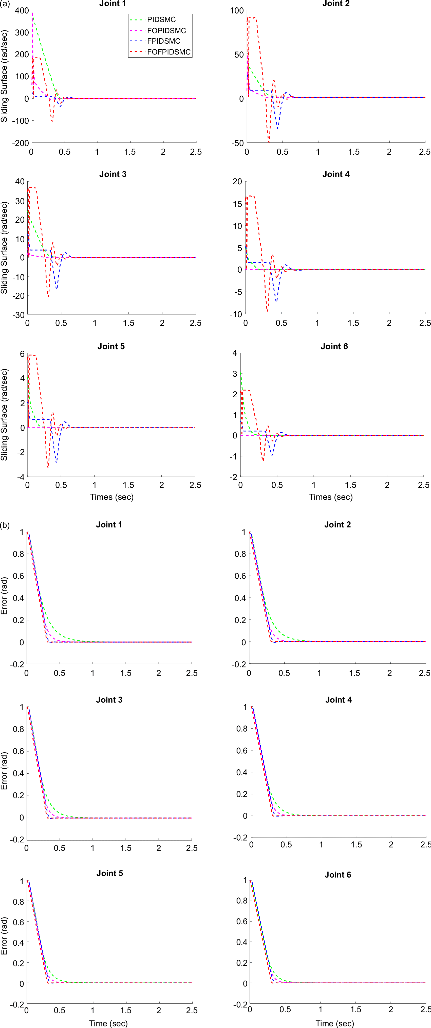
Figure 8 illustrates the sliding surfaces and tracking errors obtained for each joint using the proffered sliding mode controllers. It is evident that the suggested controllers achieve finite-time convergence and robustness of the six-joint tracking error. It is observed that for all joints, FOFPIDSMC has better performance with lower tracking errors than other controllers. A sliding mode is achieved on the sliding surface and reaches zero in finite time. Although similar behavior is observed on sliding surfaces, there are numerical differences due to the joint coupling effect depending on the dynamic structure of the joint.
Sliding surfaces (a) and trajectory tracking errors (b) for different control methodologies.

5.2. Controller performance analysis under different trajectory tracking
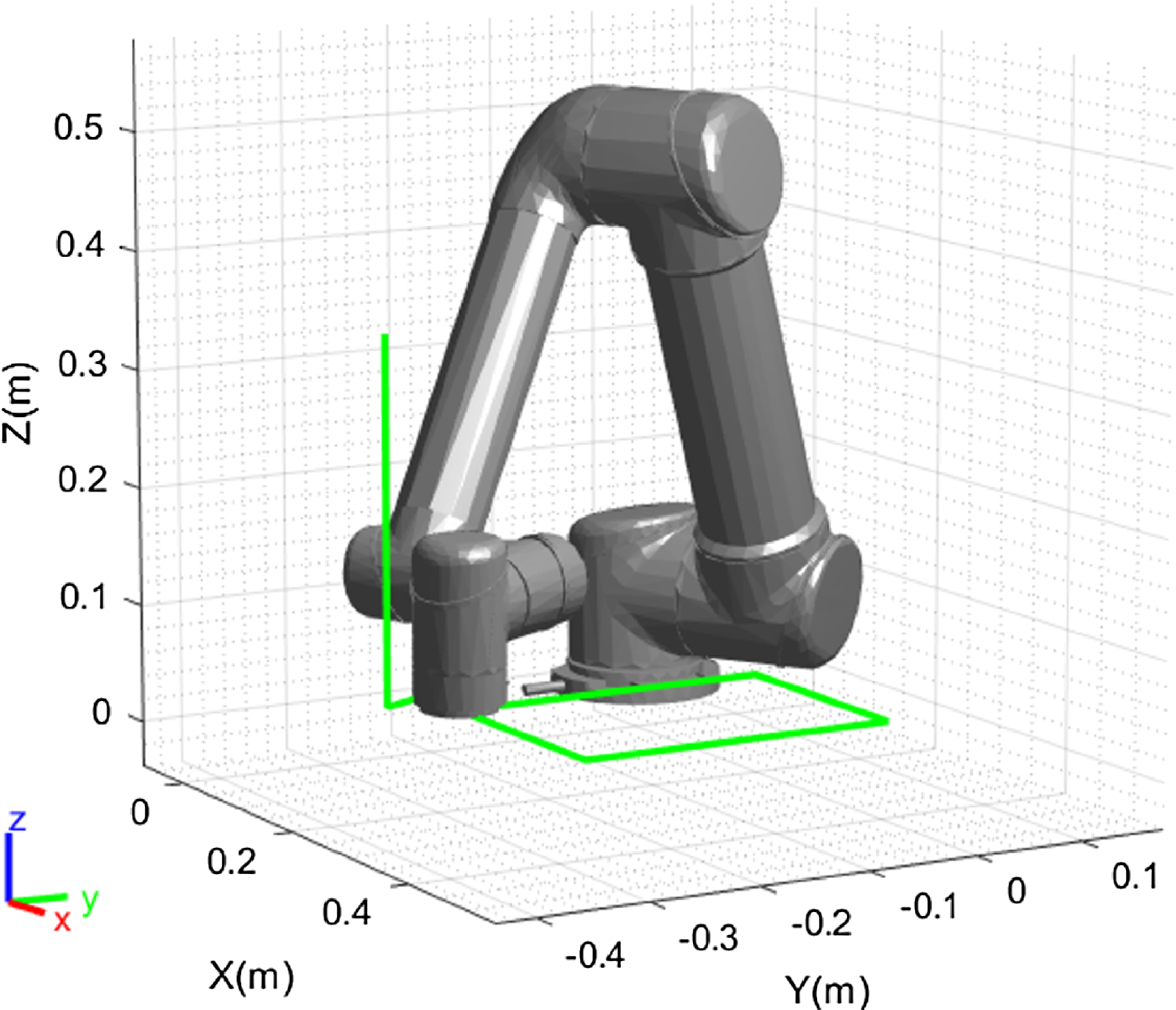
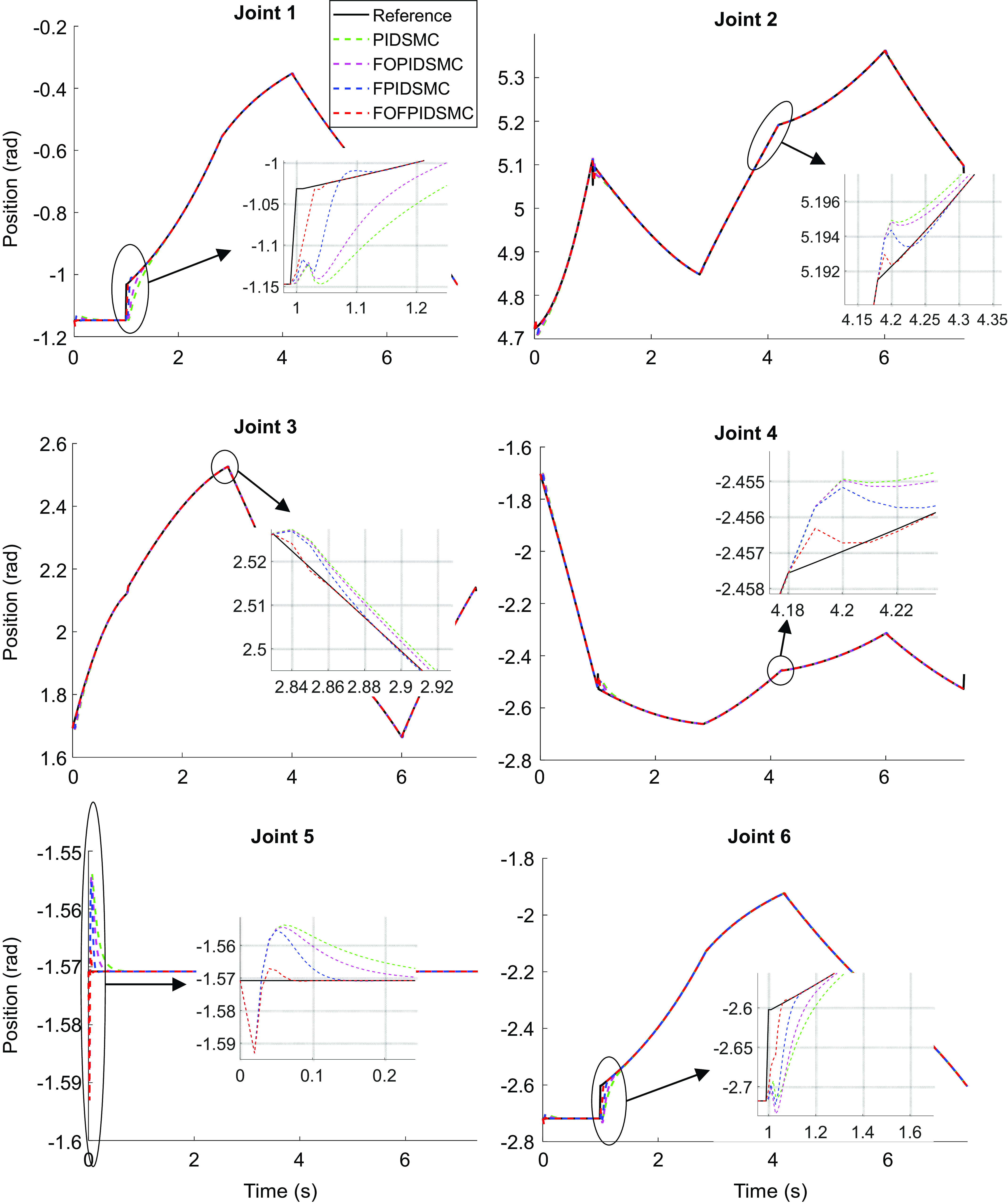
The precision of robot manipulator closed-loop control systems is examined as the end effector follows the rectangular path in Cartesian space shown in Figure 9 as the position reference. The position graphs of all joints in the joint space while the end effector of UR5 follows the rectangular trajectory in Cartesian space are presented in Figure 10. From Figure 10, it can be noticed that for all joints, FOFPIDSMC has a quicker and more precise system reaction compared to the others. Furthermore, it has been determined that according to Figure 10, the tracking accomplishment of the FOFPIDSMC controller adjusted by GWO-PSO is excellent to other controllers. This detection shows that the suggested FOFPIDSMC controller provides a preferable disturbance rejection skill in case of sudden set point replacement.
The appearance of UR5 in MATLAB with the trajectory in Cartesian space.

The performance of controllers for end effector rectangular trajectory tracking.

In addition, in order to show the control effort exerted by the controllers the RMS (Root Mean Square) of the control torque can be calculated as follows:
 \begin{equation}U_{{RMS_{i}}}=\sqrt{\frac{1}{T}\sum _{t=1}^{T}({u_{i}}(\mathrm{t}))^{2}}\end{equation}
where
 $U_{{RMS_{i}}}$
is RMS value of control signal of
 $i$
th joint, and
 $u_{i}(t)$
is control signal of
 $t$
th sample of
 $i$
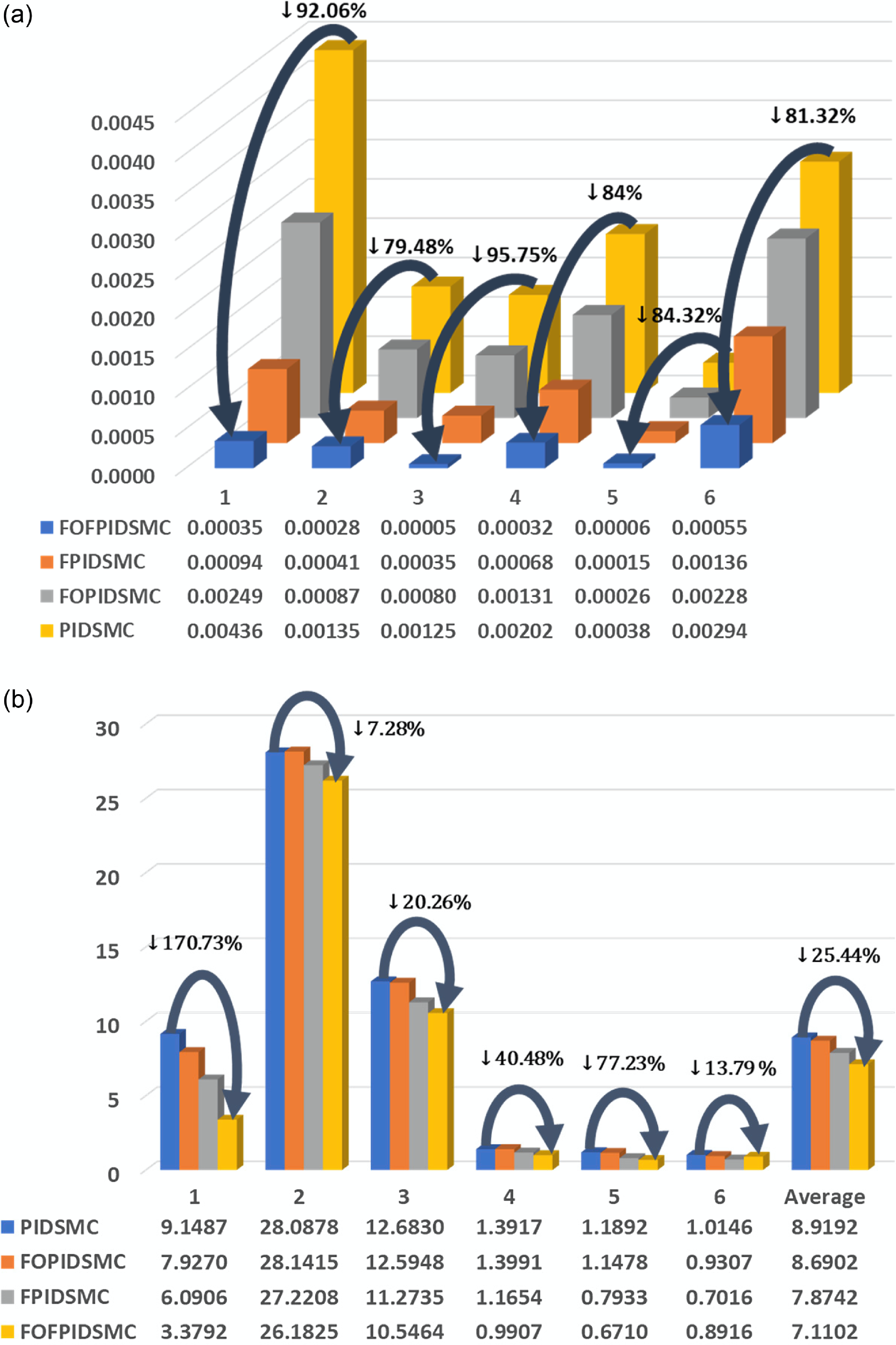
th joint. In this context, the MAE values of each joint and RMS values of the torques of each joint for the tracking efficiency of the controllers mentioned in this study are presented in Figure 11.
MAE values of each joint (a) and RMS values of the torques of each joint (b) for the tracking performance.

Considering the MAE values for each joint in Figure 11a, the tracking efficiency of the FOFPIDSMC controller compared to PIDSMC, significant improvements of 92.06% in the first joint, 79.48% in the second joint, 95.75% in the third joint, 84% in the fourth joint, 84.32% in the fifth joint, and finally 81.32% in the sixth joint were achieved, respectively. Likewise, in terms of torque RMS values of the joints, when FOFPIDSMC and PIDSMC are compared, a 25.44% performance improvement is observed in the average values of torque RMS of all joints.
This overall performance increase in torque RMS means less energy consumption during trajectory tracking. In addition, in terms of MAE, it has been revealed that the system with FOFPIDSMC controller followed the desired trajectory with less error than the other controllers (PIDSMC, FOPIDSMC, FPIDSMC), and it resulted in an improvement in the operating performance of the robot manipulator with low RMS values.
5.3. Controller performance analysis under disturbance
The main target of a robust control algorithm is to satisfactorily prevent undesirable disturbances by ensuring proper tracking of the reference trajectory. Therefore, in this study, during trajectory tracking, an external disturbance effect is applied to all joints of the robot manipulator between the controller output and the robot system for a certain period of time, with the pulse function given in Eq. (40).
 \begin{equation}\sigma _{d}\left(t\right)={\Gamma} \left[u\left(t-a\right)-u(t-b)\right]\end{equation}
 ${\Gamma}$
given in the above equation refers to the coefficient of the disturbance effect, and
 $a$
and
 $b$
refer to the start and end times of the disturbance effect.
Two different scenarios of instantaneous distortion, 0.2 s (scenario 1), and 2 s (scenario 2), were produced and applied to the base, shoulder, and elbow joints with a pulse size of 100 N-m, and three joints forming the wrist with a pulse size of 20 N-m.
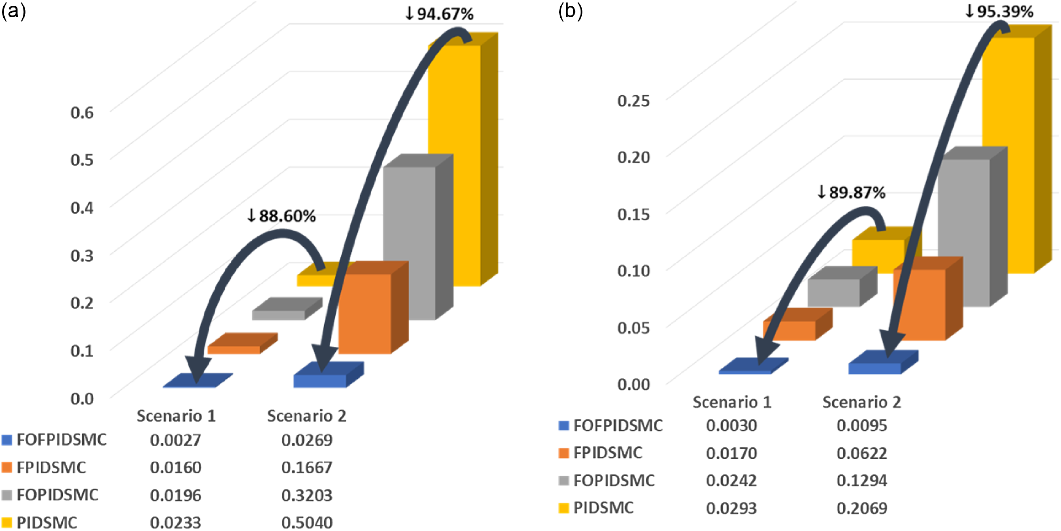
The impact of external disturbances applied to the controller output and system input while the controllers track the reference trajectory was investigated in detail for controllers adjusted by GWO-PSO. A full analysis is performed, where the averages of the MAE and torque RMS values obtained for all joints are presented graphically in Figure 12.
Averages of MAE (a) and torque RMS (b) values of all joints in disturbance rejection scenarios.

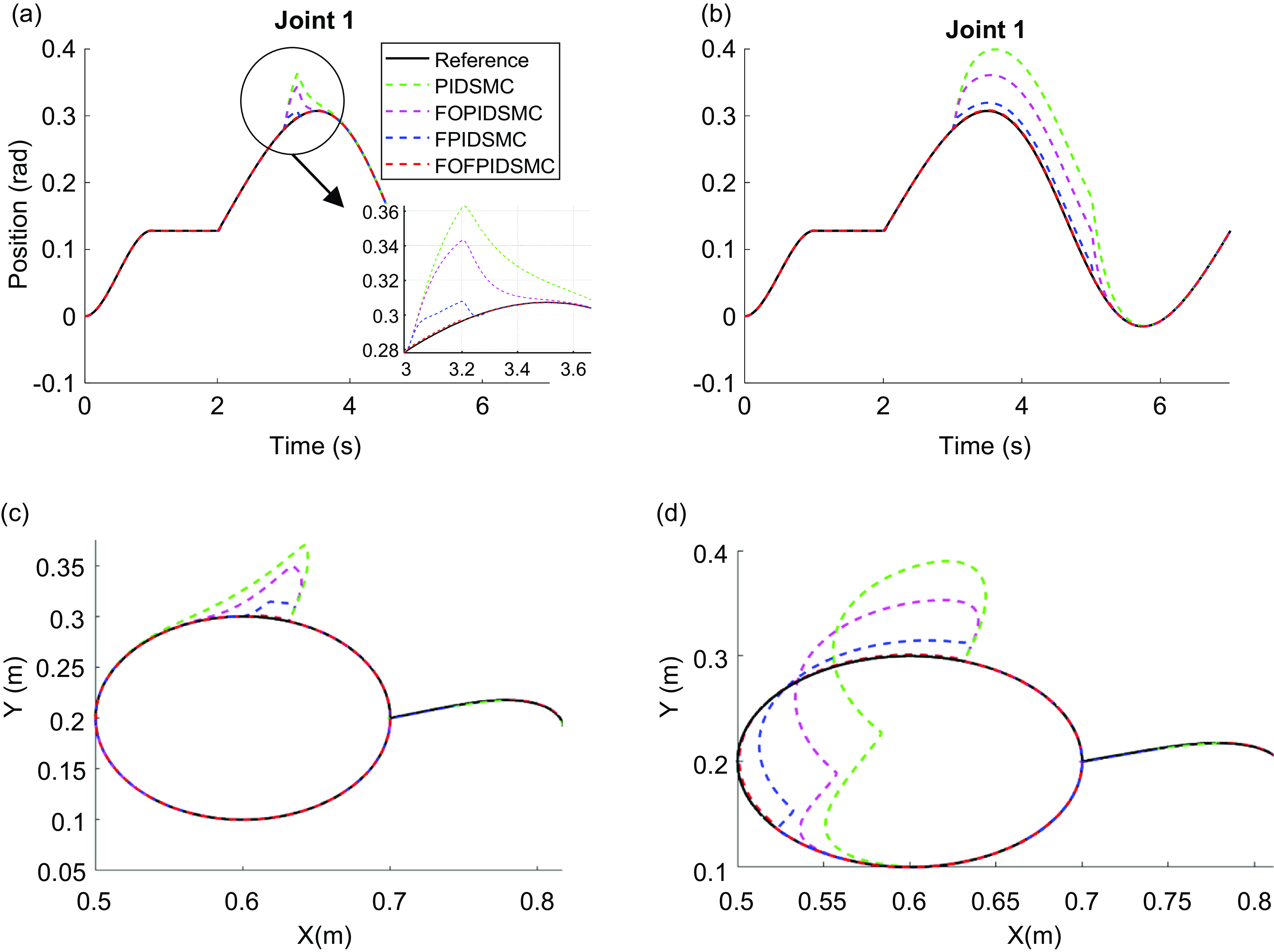
A trajectory tracking task and the Cartesian-XY position curve of the endpoint for this case are demonstrated in Figure 13 where it can be clearly observed that the FOFPIDSMC controller follows a curve closer to the reference than the other controller. After examining the obtained MAE and torque RMS values, it can be redounded that the FOFPIDSMC controller outperforms than others. From these results, it can be concluded that for scenario 1, the FOFPIDSMC controller can improve the average MAE values of all joints by 88.6%, 72.77%, and 57.42% compared to the PIDSMC, FOPIDSMC, and FPIDSMC controllers, respectively.
Scenario 1 (a) and 2 (b) trajectory tracking mission and scenario 1 (c) and 2 (d) Cartesian-XY position curve of the endpoint.

Moreover, for scenario 2, it can be issued that the FOFPIDSMC controller makes better the average MAE values of all joints by 94.67%, 58.21%, and 27.74% compared to the PIDSMC, FOPIDSMC, and FPIDSMC controllers, respectively. For another performance analysis in the mentioned disturbance scenarios, the average of the RMS values of all joints was compared. In this context, it can be observed that for scenario 1, the FOFPIDSMC controller is at a better level by 89.87%, 72.26%, and 47.7% compared to the PIDSMC, FOPIDSMC, and FPIDSMC controllers, respectively. Moreover, in scenario 2, it can be understood that the FOFPIDSMC controller controls better by 95.39%, 57.97%, and 25.46% compared to the PIDSMC, FOPIDSMC, and FPIDSMC controllers, respectively.
The proposed FOFPIDSMC controller exhibits better settling time and tracking performance relative to other controllers, as evident in Figure 13(c-d). Additionally, torque values play a crucial role in determining system energy consumption. Figure 13(a-b) demonstrates that the FOFPIDSMC controller system produces lower torque values than the others, indicating reduced energy expenditure. Situated on these findings, it can be concluded that the FOFPIDSMC controller system provides enhanced tracking performance with minimal torque under external disturbances.
5.4. Controller performance analysis under uncertainty in mass
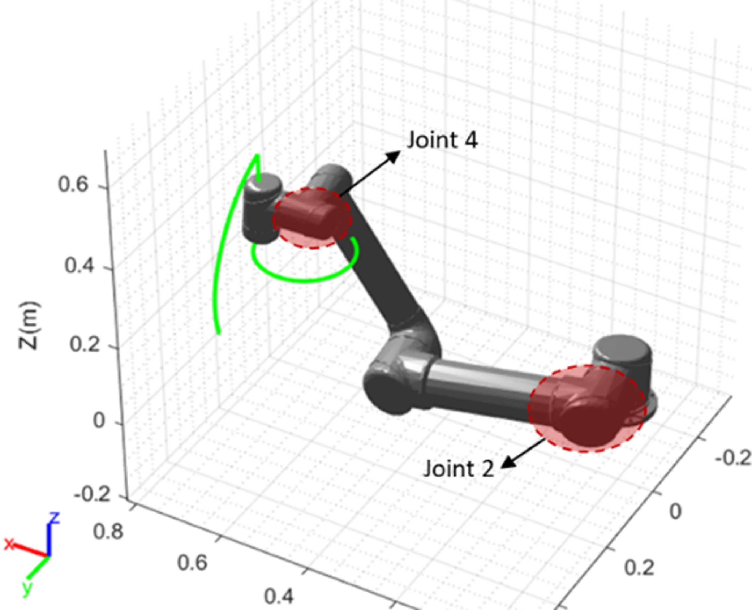
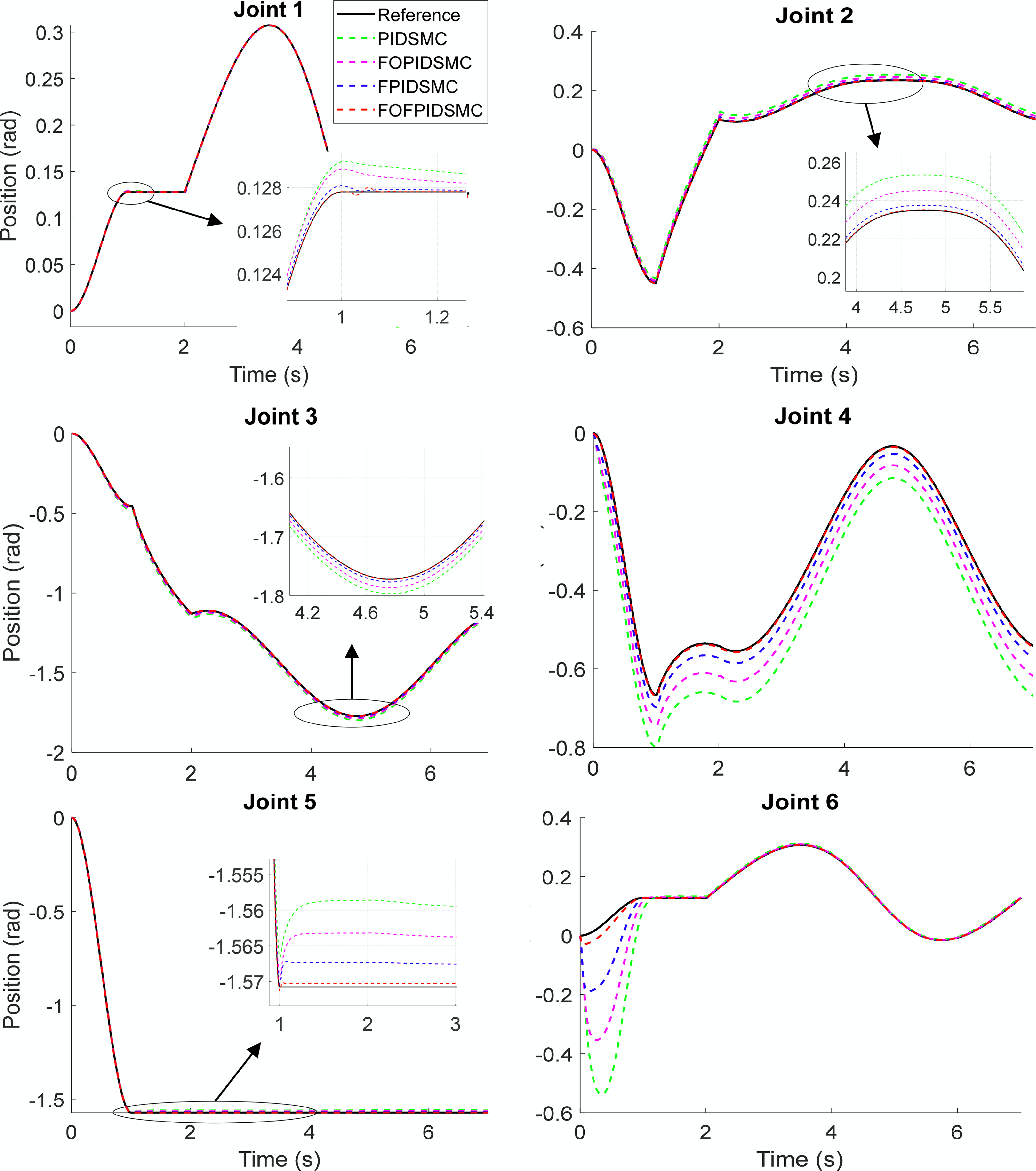
In another test of the controllers’ robustness, the mass of each link of the robot manipulator was increased to three times. For this purpose, the performance of the UR5’s end effector in tracking the parallel circle trajectory with respect to the Cartesian-XY plane of the main coordinate system was examined, as shown in Figure 14. In this trajectory tracking, it is clearly understood from Figure 15 that the second and fourth joints of the robot are more affected by the mass change due to gravity. Moreover, the FOFPIDSMC controller based on GWO-PSO performs better than other controllers from the point of convergence and steady-state error.
Robot manipulator and Cartesian-XY position curve of the endpoint.

The performance of controllers under the mass change for trajectory tracking.

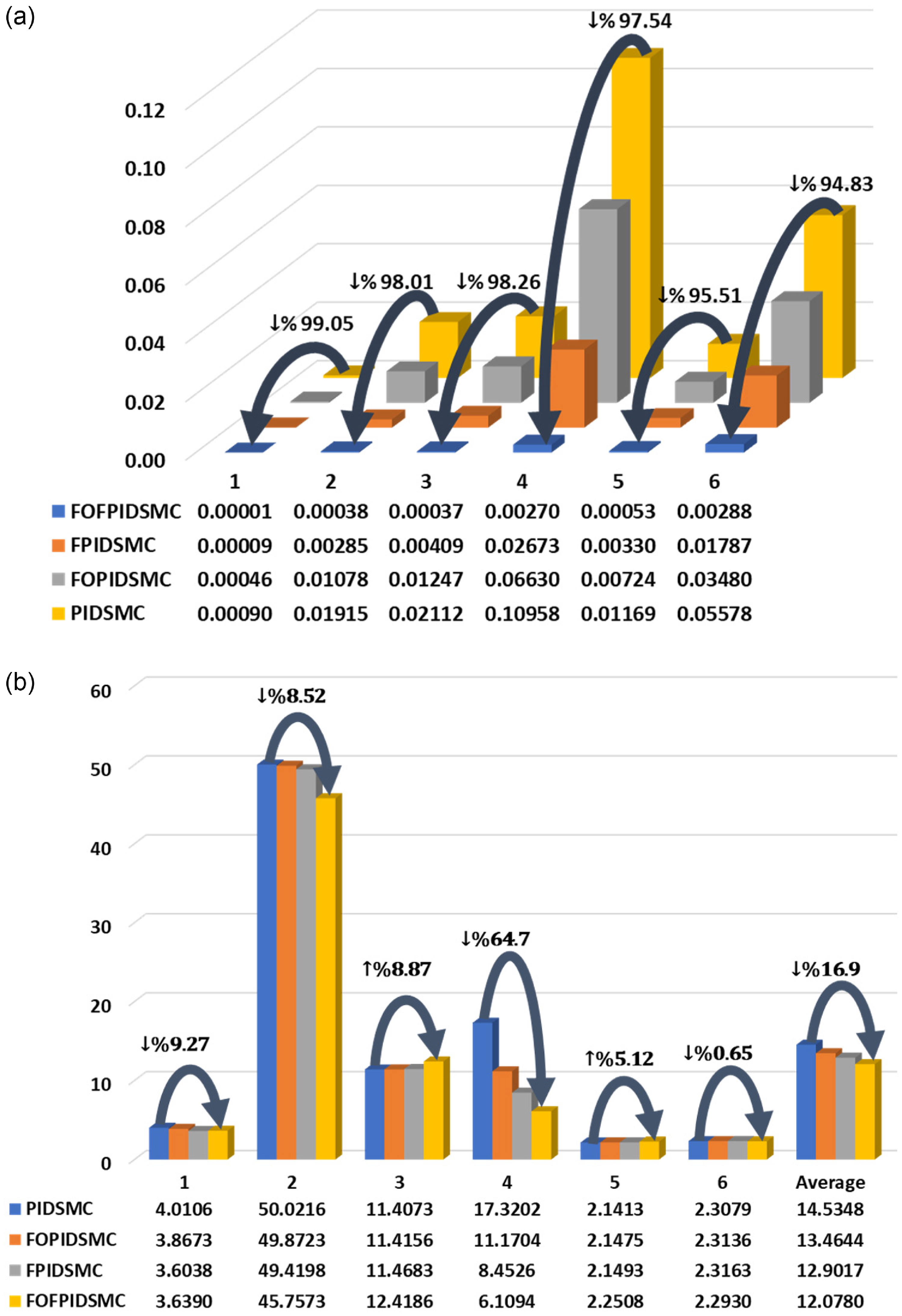
Figure 16 graphically shows the MAE and torque RMS values, where improvement is easily observed for each joint compared to the other controllers (PIDSMC, FOPIDSMC, FPIDSMC). Accordingly, improvements of 99.05%, 98.01%, 98.26%, 97.54%, 95.51%, and 94.83% were obtained in MAE values for the 1st, 2nd, 3rd, 4th, 5th, and 6th joints from the PIDSMC controller to the FOFPIDSMC side. In addition, improvements of 9.27%, 8.52%, 64.73%, 0.65%, and 16.9% were observed in torque RMS values for the 1st, 2nd, 4th, 6th joints, and average from the PIDSMC controller to the FOFPIDSMC side. However, even though there is a deterioration of 8.87% and 5.12% in torque RMS values in only the 3rd and 5th joints, FOFPIDSMC is superior in overall improvement. Based upon the mass change analysis, it can be said that the FOFPIDSMC controller outperforms the other controllers mentioned in this study.
MAE values of each joint (a) and RMS values of the torques of each joint (b) for the tracking performance under mass change.

The comprehensive comparative analysis of the proposed FOFPIDSMC controller with PIDSMC, FOPIDSMC, and FPIDSMC controllers has demonstrated significant improvements in control performance. However, it is crucial to discuss the computational complexity and real-time applicability of the proposed controller to provide additional context for its practical utility. The FOFPIDSMC controller integrates FO control and FL, which increases its computational demands compared to traditional PIDSMC, FOPIDSMC, and FPIDSMC controllers. The calculation of fractional derivatives and the fuzzy inference process require more processing power and memory. However, advancements in computational hardware and optimization techniques can mitigate these challenges.
Implementing the FOFPIDSMC controller in real-time systems presents several challenges. The increased computational load may affect the controller’s responsiveness in real-time applications. Ensuring real-time performance would require efficient algorithm optimization and possibly dedicated hardware to handle the computations without compromising the control system’s responsiveness. Despite these challenges, the proposed controller offers superior performance in terms of accuracy and robustness. Future work will focus on optimizing the algorithm for real-time applications and testing the controller on physical robotic systems to validate its practical utility and address any implementation challenges.
6. Conclusion
This study employed a comprehensive simulation analysis to evaluate the performance of PIDSMC, FOPIDSMC, FPIDSMC, and FOFPIDSMC controllers adjusted by the GWO-PSO algorithm when applied to the 6R UR5 robot manipulator system. The key findings are summarized below:
-
• Dynamic Performance Analysis: The FOFPIDSMC controller tuned by the GWO-PSO algorithm provides a dynamic response with the fastest settling time, lowest steady-state error, and MAE values. Additionally, when examined in terms of rise times, it was observed that FPIDSMC and FOFPIDSMC controllers exhibit lower values compared to other controllers for all joints.
-
• Controller Performance Analysis under Different Trajectory Tracking Conditions: Compared to other controllers, FOFPIDSMC offers faster, more accurate response and superior disturbance rejection during set point changes.
-
• Controller Performance Analysis Under Disturbance: The FOFPIDSMC controller outperforms other controllers when subjected to external disturbance effects. In scenarios with increased disturbance, the FOFPIDSMC controller significantly improves MAE and torque RMS values for all joints compared to PIDSMC, FOPIDSMC, and FPIDSMC controllers.
-
• Controller Performance Analysis Under Uncertainty in Mass: When the mass of each link of the robot manipulator is increased threefold, the FOFPIDSMC controller exhibits better resolution and steady-state error compared to other controllers. Additionally, the FOFPIDSMC controller produces lower torque values, indicating reduced energy consumption.
In conclusion, this study demonstrates that the FOFPIDSMC controller tuned by the GWO-PSO algorithm is a robust controller with excellent dynamic performance, trajectory tracking precision, disturbance rejection capability, and resilience to changes in mass for the 6R UR5 robot manipulator system. The FOFPIDSMC controller has the potential to enhance the performance of robot manipulators in real-world applications.
While the proposed control algorithms (PIDSMC, FPIDSMC, FOPIDSMC, FOFPIDSMC) offer significant advantages, it is important to acknowledge their potential drawbacks. PIDSMC can cause high-frequency oscillations (chattering) and is sensitive to sensor noise, requiring precise tuning. FPIDSMC, although powerful, involves complex design and high computational cost. FOPIDSMC presents challenges in implementation and parameter tuning due to its high-dimensional parameter space. Lastly, FOFPIDSMC combines the complexities of FO and FL control, leading to increased computational cost and a challenging tuning process.
While the simulations provide a robust analysis of the proposed control algorithms, experimental validation is essential to demonstrate their real-world applicability and performance. In particular, future studies will focus on evaluating the controllers under real-world payload conditions, where dynamic inertia and load variations can introduce significant operational challenges. Furthermore, extending the proposed control strategies to flexible-link and flexible-joint manipulators is a promising avenue. Robust fuzzy sliding mode controllers have demonstrated success in managing vibration suppression and external disturbances in flexible manipulators, as highlighted in ref. [Reference Xie, Yu and Chen53]. Similarly, advanced techniques tailored for actuators with unique dynamics, such as pneumatic muscle actuators (PMAs), have shown improved dynamic performance under uncertainties, as discussed in ref. [Reference Li, Zhang, Wu, Chen, Liu and Yao54]. Building on these approaches, the FOFPIDSMC framework could be adapted to address the challenges posed by flexible and compliant systems.
Future research will also involve experimental implementations of this controller and further investigations into its performance in different robotic manipulator systems, including parallel robots such as GSP mechanisms. Studies such as [Reference Toz and Kucuk55] and [Reference Toz and Kucuk56] highlight the unique challenges posed by parallel robots, including their complex closed-loop kinematics and derivation of inverse Jacobian matrices, as well as the tools for their design, analysis, and simulation. Leveraging these insights, the proposed FOFPIDSMC controller could be adapted to handle the distinct requirements of parallel robots, ensuring optimal performance.
These experiments will focus on replicating the simulation scenarios to ensure result consistency and address practical challenges during implementation. Preliminary experimental setups, including robotic manipulator configurations, are already being designed, with initial tests planned to commence shortly. Incorporating experimental validation will further demonstrate the robustness and effectiveness of the control strategies, providing a comprehensive analysis of their practical utility and adaptability to various robot manipulator architectures.
Author contributions
Investigation, OK and HK; conceptualization, OK and HK; methodology, OK and HK; resources, OK and HK; data curation, OK and HK; visualization, OK and HK; writing – original draft preparation, OK and HK; writing – review and editing, OK and HK; supervision, OK and HK. All authors have read and agreed to the published version of the manuscript.
Financial support
This research received no specific grant from any funding agency, commercial, or not-for-profit sectors.
Competing interests
The authors declare no conflicts of interest exist.
Ethical approval
Not applicable.
Appendix
The elements of the transformation matrix in Eq. (2) are presented below:
 \begin{equation}n_{x}=cosq_{6}\left(cosq_{5}cosq_{1}(cosq_{2}+cosq_{3}+cosq_{4})+sinq_{5}sinq_{1}\right)-sinq_{6}cosq_{1}(sinq_{2}+sinq_{3}+sinq_{4})\end{equation}
 \begin{align}n_{y} & =cosq_{6}(sinq_{1}cosq_{5}\left(cosq_{4}\left(cosq_{2}+cosq_{3}\right)-sinq_{4}\left(sinq_{2}+sinq_{3}\right)\right)-cosq_{1}sinq_{5})\nonumber\\& -sinq_{1}sinq_{6}(sinq_{4}(cosq_{2}+cosq_{3})+cosq_{4}(sinq_{2}+sinq_{3}))\end{align}
 \begin{equation}n_{z}={cosq_{5}}cosq_{6}(sinq_{2}+sinq_{3}+sinq_{4})+sinq_{6}(cosq_{2}+cosq_{3}+cosq_{4})\end{equation}
 \begin{equation}o_{x}=-sinq_{6}\left({cosq_{1}}cosq_{5}(cosq_{2}+cosq_{3}+cosq_{4})+{sinq_{1}}sinq_{5}\right)+cosq_{1}cosq_{6}(sinq_{2}+sinq_{3}+sinq_{4})\end{equation}
 \begin{align}o_{y}& =-sinq_{6}\left(sinq_{1}cosq_{5}\left(cosq_{4}(cosq_{2}+cosq_{3})-sinq_{4}(sinq_{2}+sinq_{3})\right)-cosq_{1}sinq_{5}\right)\nonumber\\& -sinq_{1}cosq_{6}(sinq_{4}(cosq_{2}+cosq_{3})+cosq_{4}(sinq_{2}+sinq_{3}))\end{align}
 \begin{equation}o_{z}=-{cosq_{5}}sinq_{6}((sinq_{2}+sinq_{3}+sinq_{4}))+cosq_{6}((cosq_{2}+cosq_{3}+cosq_{4})\end{equation}
 \begin{equation}a_{x}=-{cosq_{1}}sinq_{5}(cosq_{2}+cosq_{3}+cosq_{4})+{sinq_{1}}cosq_{5}\end{equation}
 \begin{equation}a_{y}=-sinq_{1}sinq_{5}\left(cosq_{4}(cosq_{2}+cosq_{3})-sinq_{4}(sinq_{2}+sinq_{3})\right)-cosq_{1}cosq_{5}\end{equation}
 \begin{equation}a_{z}=sinq_{5}(sinq_{2}+sinq_{3}+sinq_{4})\end{equation}
 \begin{align}p_{x}& =-d_{6}\left(cosq_{1}sinq_{5}\left(cosq_{2}+cosq_{3}+cosq_{4}\right)-{sinq_{1}}cosq_{5}\right)+d_{5}cosq_{1}(sinq_{2}+sinq_{3}+sinq_{4})\nonumber\\& +d_{4}sinq_{1}+a_{3}cosq_{1}(cosq_{2}+cosq_{3})+a_{2}cosq_{1}cosq_{2}\end{align}
 \begin{align}p_{y}& =-d_{6}(sinq_{1}sinq_{5}(cosq_{2}+cosq_{3}+cosq_{4})+cosq_{1}cosq_{5})+d_{5}sinq_{1}(sinq_{2}+sinq_{3}+sinq_{4})\nonumber\\& -d_{4}cosq_{1}+a_{3}sinq_{1}(cosq_{2}+cosq_{3})+a_{2}sinq_{1}cosq_{2}\end{align}
 \begin{equation}p_{z}=d_{1}-d_{6}sinq_{5}((sinq_{2}+sinq_{3}+sinq_{4}))-d_{5}(cosq_{2}+cosq_{3}+cosq_{4})+a_{3}(sinq_{2}+sinq_{3})+a_{2}sinq_{2}\end{equation}