I. INTRODUCTION
Since the finding of carbon nanotubes (CNTs) by IijimaReference Iijima1 in 1991, owing to their extraordinary and distinguished properties, researchers have taken much interest in exploring the immature feature and potential applications of the CNTs and also of the related carbon nanostructures.Reference Harris2 Carbon nanocones (CNCs) are one of such nanostructures that have structures similar to those of the CNTs. Ge and SattlerReference Ge and Sattler3 first proposed that there have been five types of CNCs with apex angles of 19.2, 38.9, 60, 86.6, and 123.6°, respectively. Later, Krishnan et al.Reference Krishnan, Dujardin, Treacy, Hugdhl, Lynum and Ebbesen4 verified the existence of the five types of CNCs by experimental methods. Recently, Naess et al.Reference Naess, Elgsaeter, Helgesen and Knudsen5 also studied the structure and morphology of the five types of CNCs with the aid of transmission electron microscopy, synchrotron x-ray, and electron diffraction.
With proper control of the synthetic conditions, it was found that open-tip CNCs (with their tips truncated) could be synthesized.Reference Kiselev, Hammer and Kotosonov6–Reference Endo, Kim, Hayashi, Fukai, Oshida, Terrones, Yanagisawa, Higaki and Dresselhaus8 For example, Terrones et al.Reference Terrones, Hayashi, Muñoz-Navia, Terrones, Kim, Grobert, Kamalakaran, Dorantes-Davila, Escudero, Dresselhaus and Endo7 used a chemical vapor deposition (CVD) method to synthesize open-tip CNCs and discussed the evidence of having different apex angles in the CNCs. Later, the open-tip CNCs were proved to have similar structures and the same apex angles as the closed CNCs.Reference Eksioglu and Nadarajah9 Moreover, analogous to CNTs, the CNCs can also be classified as single-walled and multiwalled CNCs according to the number of layers comprising the nanocones.Reference Iijima, Yudasaka, Yamada, Bandow, Suenaga, Kokai and Taskahashi10–Reference Zhang, Jiang and Wang12 Mass production of CNCs is possible with the assistance of plasma. For example, Tsakadze et al.Reference Tsakadze, Levchenko, Ostrikov and Su13 used a plasma-assisted chemical vapor deposition method to grow uniform CNCs arrays. Their group also proposed a plasma-assisted model for the growth of sharp-tip and flat-tip CNCs arrays.Reference Levchenko, Ostrikov, Long and Xu14
Because CNCs have their special cone shapes, their tip structures can provide high resolution and/or high intensity in practical applications. Hence, they are ideally suitable for use as scanning probe tips and electron field emittersReference Krishnan, Dujardin, Treacy, Hugdhl, Lynum and Ebbesen4 and have potential applications in nanoindentations.Reference Hsieh, Chen, Chen, Chen and Hwang15 With regard to these applications, Chen et al.Reference Chen, Chen, Gapin, Jin, Yuan and Liou16 had used CNCs as proximal probe tips in magnetic force microscopy (MFM) for high-resolution MFM imaging. Yu and ZhengReference Yu and Zheng17 investigated the effects of nitrogen/boron doping on the electronic and field-emission properties for CNTs, CNCs, and graphene nanoribbons.
For exploration and promotion of applications for CNCs, it is worthy to understand the mechanical behaviors, such as deformation, strength, stiffness, and stability of CNCs. Concerning this issue, to the authors’ knowledge, not many research works were found in the available literature. Jordan and CrespiReference Jordan and Crespi18 utilized the molecular dynamics (MD) simulations to investigate mechanical chiral inversion of CNCs under compression by a spherical indenter on their apexes. Tsai and FangReference Tsai and Fang19 performed a MD study on the nucleation, thermal stability, and nanomechanics of CNCs. Liew et al.Reference Liew, Wei and He20 also used MD simulations to investigate buckling and postbuckling behaviors of open-tip CNCs with apex angles of 19.2°. Their group later examined mechanical properties of the open-tip CNCs under tensile loading.Reference Wei, Liew and He21
To enrich information on mechanical behaviors of CNCs for their potential applications, tensile and compressive behaviors of open-tip CNCs under axial strains (including tensile strains and compressive strains) were investigated in this study with the aid of the MD simulations. Tensile behaviors (such as the failure strain, failure loads, and failure modes) and compressive behaviors (such as the critical strains, critical loads, and buckling modes) of the CNCs were studied. The influences of temperature, cone height, and apex angle on the behaviors were examined in the study. In contrast to fewer related works to this study, there are plenty of research works on tensile and compressive behaviors of CNTs. The examples are the pioneering studies by Yakobson et al.Reference Yakobson, Brabec and Bernholc22, Reference Yakobson, Campbell, Brabec and Bernholc23 They first investigated compression instabilities of CNTs under large deformationReference Yakobson, Brabec and Bernholc22 and then examined the tensile failure of CNTsReference Yakobson, Campbell, Brabec and Bernholc23 via the MD simulations. Influences of temperature on the breaking strain were also discussed in the later research work. Because CNCs have structures similar to those of CNTs, results of the above studies can be utilized for comparison of the behaviors of CNCs and CNTs.
The simulation method and verification of the present method are described in the following section.
II. SIMULATION METHOD AND MODEL
A. Simulation method
The MD simulations were used in this study. In the simulations, the Tersoff bond-order potential was selected to model interactions of carbon atoms of the CNCs because it is very efficient in the simulations of CNC systems.Reference Tsai and Fang19 The Tersoff bond-order potential can be expressed asReference Tersoff24, Reference Tersoff25

where V is the potential energy of the CNC system; Vij is the bond energy of atoms i and j, which can be written as

in which fc(rij) represents a smooth cutoff function, rij is the distance between atoms i and j, and VR(rij) and VA(rij) are the repulsive and attractive energies between atoms i and j, respectively. The function bij is the bond order of atoms i and j and is the feature of the Tersoff bond-order potential. Expressions of the above functions and their related parameters can be obtained from the literature.Reference Tersoff25
With the potential function of Eq. (1), interaction forces between the carbon atoms can be calculated from the gradient of the potential function. The equations of motion for the CNC system can then be set with the aid of the interaction forces. Through integrating the equations of motion, evolution of each atom of the system can be attained, from which behaviors of the system can be evaluated via statistical analysis. In this study, NVT (canonical) ensembles were used for the statistical analysis. For efficiency of the simulations, the velocity rescaling methodReference Haile26, Reference Rapaport27 was utilized as the thermostat during the simulations. Besides, the velocity Verlet algorithmReference Haile26, Reference Rapaport27 with a time step of 1 fs (10−15 s) was selected for the integration of the equations of motion.
B. Simulation model and verification of the model
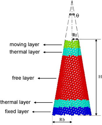
In this study, a displacement control method was used to simulate the axial strains (including tensile strains and compressive strains) applied on the CNCs. The simulation model is illustrated in Fig. 1. The open-tip CNC has an apex angle θ, top radius Rt, bottom radius Rb, and cone height H (the height from the position of the bottom radius to that of the top radius). It was partitioned into several regions. The uppermost region is a moving layer, in which atoms are displaced gradually in the axial direction at a very small and constant speed away from (or toward) the bottom of the CNC to simulate the tensile (or compressive) strains. The lowest region is a fixed layer, in which atoms are fixed during the simulations. Next to the moving layer and the fixed layer, there are thermal layers, in which atoms act as a thermostat and are subjected to the thermal control method. The remaining region is a free layer, in which atoms are free to evolve without any constraint during the simulations. Height of the moving layer, the fixed layer, and each thermal layer is set as a tenth of the total height of the CNC. As a result, the regions subjected to axial strains are the thermal layers and the free layer.
Simulation model of this study.

It should be noted that, during the simulations, positions of the fixed layer atoms were fixed (unmovable) to model the fixture applied on the CNC during the application of axial strains. Positions of the moving layer atoms were specified by a constant displacement rate to model the applied axial strains. Atoms in the moving layer and the fixed layer were not affected by the interatomic forces (i.e., by the potential function). However, atoms in these two layers also applied interatomic forces on atoms in the thermal layers and the free layer. Arrangement of the thermal layers in the present simulation model is to control the temperature of the simulation system to approach a constant value prescribed by the problem considered.
As a test example for the validity of the present simulation model, a problem in the study by Liew et al.Reference Liew, Wei and He20 was also illustrated. The open-tip CNC under consideration has an apex angle θ = 19.2°, top radius Rt = 6 Å, bottom radius Rb = 18.5 Å, and cone height H = 74 Å. Since the study by Liew et al. was carried out without temperature control, for comparison purpose, the temperature in the present test example was set at a very small value of 1 K. At the beginning (before applying the compression), the open-tip CNC was subjected to the MD simulations for a period of 105 fs to achieve an unloaded equilibrium state. This process could relax artificial constraints, which were introduced during the construction of the simulation model. The compressive strain was then applied by displacing the moving layer inwardly and gradually in the axial direction at a very small constant rate of 10 m/s, which was selected same as that of the literature.Reference Liew, Wei and He20 Data before and during the loading process were recorded for statistical analysis of the related quantities.
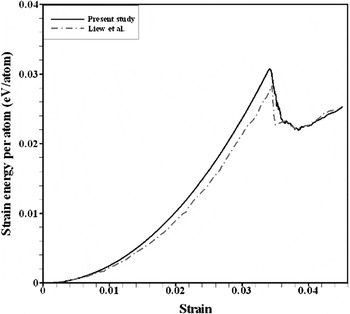
Average strain energy calculated from the present simulation model and that by Liew et al. are displayed in Fig. 2. Average compressive strains were used in the figure, which were calculated from dividing the axial displacements by the length of strained region. Quite agreements between both studies can be seen. The critical strain of this study is 3.42%, which is much close to the value 3.45% of the literature. The deviation may ascribe to different potential functions used in both studies. In contrast to the Tersoff bond-order potential utilized in the present simulations, the second-generation reactive empirical bond-order (REBO) potential of Brenner et al.Reference Brenner, Shenderova, Harrison, Stuart, Ni and Sinnott28 was used in the work of the literature. Besides, the study by Liew et al. was performed without temperature control rather than the NVT ensembles of the present simulations. This may also result in the deviation of both studies. In spite of the small deviation, validity of the present simulation model could be verified.
Comparison of the average strain energy calculated from this study and that from the literatureReference Liew, Wei and He20 for the test example: an open-tip carbon nanocone (CNC) under axial compressive strains.

To explain the reason why the Tersoff bond-order potential was selected in this study, the differences between the Tersoff bond-order potential and the second-generation REBO potential are discussed briefly. The second-generation REBO potential was proposed based on the Tersoff bond-order potential with special corrections to the bond order term for remedying the overbinding of radicals for bonds between pairs of atoms which have different coordinations and for considering the dihedral angle for double bonds.Reference Brenner, Shenderova, Harrison, Stuart, Ni and Sinnott28 Owing to these corrections, the second-generation REBO potential allows for bond breaking and bond formation to occur in the simulations. As a result, the second-generation REBO potential has been widely used for investigations of mechanical behaviors of carbon nanostructures, although it is more complicated and less computationally efficient than the Tersoff bond-order potential. In this study, because temperature influences on mechanical behaviors of open-tip CNCs were examined, increments in the temperature should be controlled gradually and slowly to attain stable and accurate results. Computational efficiency is critical for the study. To simplify the simulation procedures, the Tersoff bond-order potential, thus, was utilized in the study.
III. RESULTS AND DISCUSSION
With the simulation model, tensile behaviors and compressive behaviors of the CNCs under axial tensile strains and axial compressive strains, respectively, were investigated. Influences of temperature, cone height, and apex angle on the behaviors were examined. Results were discussed as follows.
A. Tensile behaviors
For tensile behaviors of the CNC, an open-tip CNC with the apex angle of 19.2°, top radius of 5 Å, bottom radius of 15 Å, and cone height of 60 Å under axial tensile strains was studied first. To examine the influences of temperature on the tensile behaviors, temperatures of 1, 100, 300, and 500 K were considered in this example. The kinetic energy of the CNC increases as the system temperature increases. This may cause the CNC structure oscillating greatly at high temperatures and increase difficulty of the MD simulations. To diminish the difficulty and to obtain more stable results, the displacement rate of the moving layer was reduced to 0.1 m/s in this example. For ease of comparison and discussion, this displacement rate was also utilized in the following examples.
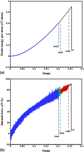
The average strain energy and internal axial force versus the average tensile strain of the CNC at various temperatures are plotted in Fig. 3. The average strain energy was calculated by averaging the strain energy of atoms in the thermal layers and the free layer (i.e., in the strained regions). The internal axial force was determined by summing the forces in the axial direction acting on the atoms in the upper thermal layer and the free layer by the atoms in the moving layer. It was noticed from the figure that the failure tensile strain and the failure average strain energy of the CNC decrease evidently with an increase in the temperature. The failure strain decreases from 25.5% at temperature 1 K to 20.2% at temperature 500 K. The corresponding internal axial force decreases from 91.3 to 70.7 eV/Å. Oscillation of the internal force because of the increase in kinetic energy becomes apparent as the temperature increases. Moreover, from curves of the internal axial force versus the average tensile strain, no obvious yielding was observed before the failure of the CNC.
The average strain energy and internal axial force versus the average tensile strain of the CNC at various temperatures.

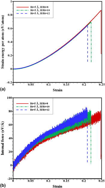
Figure 4 shows the average strain energy and internal axial force versus the average tensile strain of the CNCs at temperature 300 K with different cone heights of 40, 50, and 60 Å (i.e., with H/Rt of 8, 10, and 12, respectively). The failure tensile strain was observed to decrease as the cone height increases, with the failure strain of 24.8, 22.0, and 21.0% for the cone height of 40, 50, and 60 Å, respectively. The failure internal force was noticed to vary unclearly in a small range of 75–79 eV/Å. Similar behaviors were also noted for the cases at the different temperatures studied.
The average strain energy and internal axial force versus the average tensile strain of the CNCs with various cone heights.

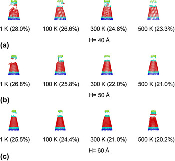
Failure modes of the CNCs, with various cone heights, at various temperatures are shown in Fig. 5. Values in the parentheses of the figure indicate the corresponding tensile strain at which the failure mode occurred. Despite the cone height and system temperature, the CNCs were found to break near the top end of the CNC. Because the CNC does not have uniform radius along its cone axis, the region near the top end has a smaller cross-section area owing to its smaller radius. Thus, the CNCs may break near the top (narrowest) end at the failure strain. The break occurring near the top end rather than at the top end is ascribed to the thermal oscillation of the cone body caused by the system temperature. Owing to the near-top-end breaking mode, the cone height does not have evident influences on the failure load of the CNC. With the same reasoning, the failure tensile strain decreases with the growth of the cone height because the average tensile strain was used in the study. It was calculated from dividing the axial displacement at failure by the length of strained region, which is proportional to the cone height of the CNC.
Failure modes of the CNCs, with various cone heights, at various temperatures. Values in the parentheses indicate the corresponding average tensile strain at which the failure mode occurred.

To study the influences of the thermal layer height (thickness) on the simulations results, simulations were also carried out for the CNC using simulation models with different thermal layer heights. These included the models with thermal layer height of H/10, 2H/10, and 4H/10 (where H denoting the cone height). No evident variations were noticed among the simulation results. The thermal layer height does not have apparent influences on the failure tensile strain, failure internal force, and failure mode. The tensile failure occurred close or at the top thermal layer because the CNC has a smaller cross-section area in this region when compared with other regions. This caused a larger axial stress and easier failure in this region when the CNC was applied by the axial tensile strains.
Compared with the tensile behaviors of the CNT,Reference Yakobson, Campbell, Brabec and Bernholc23 temperature has the same influences on the failure strain of both the CNC and the CNT. However, because the CNC does not have uniform radius along its cone axis, it breaks near the top end of the CNC rather than that occurring near the middle of the CNT. In addition, the evident plastic deformation before complete breaking of the CNT was not found in this study for the CNC.
B. Compressive behaviors
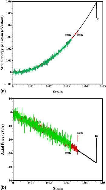
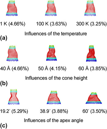
Regarding compressive behaviors of the CNC, an open-tip CNC with the apex angle of 19.2°, top radius of 5 Å, bottom radius of 11.6 Å, and cone height of 40 Å was analyzed first. For ease of discussion, temperatures of 1, 100, and 300 K were considered to investigate influences of temperature on compressive behaviors of the CNC. The average strain energy and internal axial force versus the average compressive strain of the CNC are displayed in Fig. 6. A negative value of the internal axial force stands for a compressive force. It was noticed that the critical strain of the CNC decreases evidently with an increase in the temperature. At temperatures of 1, 100, and 300 K, the corresponding critical strains are 4.63, 3.59, and 3.22%, respectively. The corresponding critical loads are 36.8, 28.5, and 23.6 eV/Å, respectively. The antibuckling ability of the CNC decreases as the temperature rises. Figure 9(a) depicts the corresponding buckling mode of the CNC. Postbuckling behaviors of the CNC can be seen from the buckling mode. Values in the parentheses of the figure indicate the corresponding compressive strain at which the buckling mode occurred. It was observed from the figure that the buckling mode does not have much variation when the temperature increases. This implies that the system temperature does not have apparent influences on the buckling mode of the open-tip CNC.
The average strain energy and internal axial force versus the average compressive strain of the CNC at various temperatures.

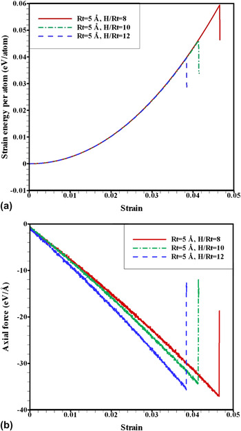
To explore the influences of the cone height on compressive behaviors of the CNC, three open-tip CNCs with the same apex angle of 19.2° and top radius (Rt) of 5 Å, but with different cone heights (H) of 40, 50, and 60 Å (i.e., with a slenderness ratio H/Rt of 8, 10, and 12, respectively), were chosen. For comparison purpose, the temperature in this example was set to be 1 K. Figure 7 compares the average strain energy and internal axial force versus the average compressive strain for the three CNCs. The critical strain and the critical average strain energy were noticed to decrease with the increase in the cone height. For the CNCs with cone heights of 40, 50, and 60 Å, the corresponding critical strains are 4.63, 4.13, and 3.83%, respectively. The antibuckling ability of the CNCs decreases as the cone height increases, namely, as the slenderness ratio increases. It was also noted that variation in the critical loads is not clear (range 34.4–36.8 eV/Å). Similar behaviors were also observed for the cases at the different temperatures. The nonuniform radius along the cone axis also results in these behaviors. Buckling modes of the three CNCs are plotted in Fig. 9(b).The buckling modes exhibit a slightly different pattern. With larger cone height, the CNC displays a more distorted buckling pattern. This is ascribed to the increase in the slenderness ratio (H/Rt) of the cone structure.
The average strain energy and internal axial force versus the average compressive strain of the CNC with various cone heights.

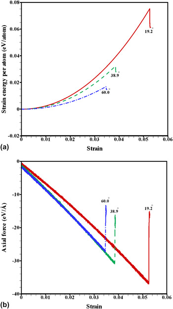
For inspection of influences of the apex angle on compressive behaviors of the CNC, three open-tip CNCs with the same top radius of 5 Å and cone height of 30 Å but different apex angles of 19.2, 38.9, and 60°, respectively, were studied. The system temperature was also set to be 1 K. The average strain energy and internal axial force versus the average compressive strain for the three CNCs are compared in Fig. 8. It was found that the critical strain of the CNCs decreases with an increase in the apex angle. For the CNCs with apex angles of 19.2, 38.9, and 60°, the corresponding critical strains are 5.25, 3.83, and 3.46%, respectively. The corresponding critical load also decreases with the expansion of the apex angle (with values of 36.8, 30.3, and 27.3 eV/Å, respectively). Reduction in rigidity in the axial direction because of the expansion of the apex angle results in the decrease of the antibuckling ability of the CNC. Buckling modes of the three CNCs are shown in Fig. 9(c). As can be seen from the figure, there are apparent differences between the buckling modes of the three CNCs. The CNC with an apex angle of 19.2° exhibits an axisymmetric buckling mode about its cone axis. With the increase in the apex angle, the buckling mode transfers from an axisymmetric pattern to an unsymmetrical and more warped pattern owing to the reduction in rigidity of the CNCs.
The average strain energy and internal axial force versus the average compressive strain of the CNC with various apex angles.

Influences of the temperature, cone height, and apex angle on the buckling mode of the CNC. Values in the parentheses indicate the corresponding average compressive strain at which the buckling mode occurred.

It should be noted that the axisymmetric buckling mode is similar to that found in the compression of CNTs.Reference Yakobson, Brabec and Bernholc22 As the apex angle expands, geometry of the CNC becomes much far from that of the CNT. Therefore, the buckling mode transfers from like that of the CNT (an axisymmetric pattern) to far from that of the CNT (an unsymmetrical and more warped pattern).
IV. CONCLUSIONS
A simulation model, together with MD simulations, has been applied to the investigation of tensile and compressive behaviors of open-tip CNCs under axial strains. The Tersoff bond-order potential was utilized in the MD simulations. Validity of the simulation model was verified by a test example of the available literature. With the simulation model, influences of the temperature, cone height, and apex angle on the tensile and compressive behaviors were examined in the study.
From the results of this study, it was noticed that the tensile failure strain and failure load of the open-tip CNC diminish evidently as the system temperature increases. No obvious yielding was observed before the tensile failure of the CNC. Because the CNC does not have uniform radius along its cone axis, it breaks near the top end of the CNC at the failure strain. Owing to the near-top-end breaking mode, the failure strain (averaged) decreases with the growth of the cone height. However, the failure load is not obviously influenced by the cone height of the CNC.
Regarding the compressive behaviors, the critical strain and critical load of the CNC reduce apparently with the increase in the system temperature and the apex angle. As the cone height of the CNC grows, the critical strain decreases evidently owing to the increase in the slenderness ratio. However, the cone height also has no obvious influences on the critical load because of the nonuniform radius along the cone axis of the CNC. The buckling mode does not have much variation when the temperature increases. As the cone height enlarges, the buckling mode displays a more distorted buckling pattern because of the increase in the slenderness. Moreover, with the expansion of the apex angle, the buckling mode transfers from an axisymmetric pattern for the CNC with the smallest apex angle (19.2°) to an unsymmetrical and more warped pattern because of the reduction in rigidity of the CNC.
As mentioned previously, owing to their special cone shape, CNCs are particularly suitable for use as scanning probe tips, electron field emitters, and nanoindenters. Concerning these applications, the resolution for scanning probe tips and nanoindenters and the turn-on power for electron field emitters are the critical factors affecting their performance. Besides, mechanical behaviors (such as the antibuckling ability) of the CNCs must also be considered. After concerning the above factors, the CNC with the smallest apex angle (19.2°) is the best candidate for these applications because it can provide the most favorable characteristics among the five CNCs. However, the tip of the closed 19.2° CNC is very sharp and flexible for the use in the applications. The open-tip 19.2° CNC may offer an alternative for the applications. This study has investigated the influences of several factors on tensile and compressive behaviors of open-tip CNCs. The results of the study might provide some information that is useful for these applications of CNCs.
ACKNOWLEDGMENT
The authors thank the support provided to this research by the National Science Council of the Republic of China under Grant No. NSC 97-2623-E006-001-MY3.