Introduction
Finite Element Method (FEM) is a powerful, versatile, and widely used numerical technique, thanks to its good efficiency and flexibility, allowing the modelization of anisotropic and inhomogeneous materials with ease [Reference Pelosi, Coccioli and Selleri1]. A fully 3D analysis with FEM however is demanding in terms of CPU and memory resources, and the accuracy of the solution obtained often depends on the quality of the mesh used in the discretization. 2.5D FEM, when applicable, offer very significant memory and CPU-time savings and, relying on a 2D mesh, it is much easier to obtain a good quality mesh. Examples of 2.5D FEM are the classical Body-of-Revolution (BoR) formulation [Reference Greenwood and Jin2,Reference Gentili, Bolli, Nesti, Pelosi and Toso3], and some more general methods that use 2.5D FEM combined with a sinusoidal expansion [Reference Gentili, Accatino and Bertin4]. In this work we use 2.5D FEM in its BoR formulation combined with a coordinate transform for the analysis of elliptical structures with constant axial ratio. Although the general case of arbitrary z-dependent axial ratio has been analyzed in [Reference Gentili, Khosronejad, Nesti, Pelosi and Selleri5], the case of constant axial ratio introduces some simplifications in the formulation and is more efficient, due to the particular structure of FEM matrices. A further difference with respect to [Reference Gentili, Khosronejad, Nesti, Pelosi and Selleri5] is represented by the forcing term: in this paper, the structure is necessarily fed by an elliptical waveguide and the scattering matrix has been computed by a deembedding procedure, discussed in the following.
BoR-FEM can be used for elliptical structures thanks to a coordinate transformation, also named “Transformation Optics” (TO), or “Transformation Electromagnetics”, a rather new approach to electromagnetic design [Reference Kundtz, Smith and Pendry6]. In the literature, TO has been exploited for different scopes, such as antenna design [Reference Kundtz, Smith and Pendry6–Reference Mateo-Segura, Dyke, Dyke, Haq and Hao9], cloaking, or pattern manipulation [Reference Keivaan, Fakheri, Abdolali and Oraizi10–Reference Kwon14]. In this work and in [Reference Gentili, Khosronejad, Nesti, Pelosi and Selleri5] we adopt it with a different point of view, since we use TO as a tool to convert the original geometry to a shape suitable to be modeled by BoR-FEM, with huge savings in terms of memory allocation and CPU-time. We show the application of this technique to some elliptical shape components, such as transitions and horns. In particular, horns are still rather demanding in terms of computer resources, because of the rather large size in terms of wavelength and because of the need to account for the outer boundaries. Various methods have been used for the analysis of elliptical horns, but they are all fully 3D [Reference Clarricoats and Olver15,Reference Tomassoni, Mongiardo, Kuhn and Omar16]. In these structures, the advantage of BoR-FEM, i.e. of 2.5D FEM, is a major one, because of the clever use of specific problem-dependent basis functions and of the 2D mesh.
The organization of the paper is the following, at first we briefly recall the basics of TO (section “Transformations optics”), then we present the BoR-FEM formulation (section “BoR-FEM formulation”). A detailed description of the matrix structure is then presented in section “Matrix structure and post-processing”, together with a discussion on the computation of the scattering matrix and of the radiation fields. Finally, some results are presented for validation purposes, confirming the efficiency of the technique and the excellent accuracy. A final section concludes the paper, with a quick resume of the main results found.
Transformations optics
General coordinate transformations in the frame of Maxwell's equations are well known. For any given coordinate transformation, Maxwell's equations can be written in identical form, if simple transformations are applied to materials and fields.
Let's assume to have a starting, or “original”, system of coordinates (x′, y′, z′) and a second, or “transformed” system of coordinates (x, y, z) linked by
 $$x = x(x',y',z')$$
 $$y = y(x',y',z')$$
 $$z = z(x',y',z')$$
with an associated Jacobian matrix
 $${\bf J} = \left[\matrix{\displaystyle{{\partial x}\over{\partial x'}} & \displaystyle{{\partial x}\over{\partial y'}} & \displaystyle{{\partial x}\over{\partial z'}} \cr \displaystyle{{\partial y}\over{\partial x'}} & \displaystyle{{\partial y}\over{\partial y'}} & \displaystyle{{\partial y}\over{\partial z'}} \cr \displaystyle{{\partial z}\over{\partial x'}} & \displaystyle{{\partial z}\over{\partial y'}} & \displaystyle{{\partial z}\over{\partial z'}}}\right].$$
If e′ and h′ are the solution of Maxwell's equations for a given problem in the original coordinate frame x′, y′, z′, with material parameters characterized by tensors  ${\bf \epsilon }'$ and
 ${\bf \mu}'$, then if in the transformed frame (x, y, z) the material properties are set to
 $$ {{\bf \epsilon}}_r = \displaystyle{{{\bf J}{{\bf \epsilon}}'_r{{\bf J}}^{\rm T}}\over{\det{{\bf J}}}}$$
 $$ {{\bf \mu}}_r = \displaystyle{{{\bf J}{{\bf \mu}'}_r{{\bf J}}^{\rm T}}\over{\det{{\bf J}}}}$$
the electric and magnetic fields e and h in frame (x, y, z) and those in the original frame are related by
 $${\bf e}'= {\bf J}^{\rm T}{\bf e}$$
 $$ {\bf h}'= {\bf J}^{\rm T}{\bf h}.$$
In our case, TO is used to convert the elliptical geometry to a circular one, for which the very efficient BoR-FEM formulation can be applied. In this paper, we focus on the case of constant axial ration, for which the transformation is very simple:
 $$\eqalign{xs & = x' \cr y & = y' \cr z &= z'}$$
in which
 $$ s = \displaystyle{{a}\over{b}}$$
being a, b the ellipse semi-axes along x and y respectively. Transformation (9) converts ellipses in (x′, y′) plane to circles in (x, y) plane with radius b. The Jacobian of the transformation is
 $$ {{\bf J}} = \left[\matrix{\displaystyle{{\partial x}\over{\partial x'}} & \displaystyle{{\partial x}\over{\partial y'}} & \displaystyle{{\partial x}\over{\partial z'}} \cr \displaystyle{{\partial y}\over{\partial x'}} & \displaystyle{{\partial y}\over{\partial y'}} &\displaystyle{{\partial y}\over{\partial z'}} \cr \displaystyle{{\partial z}\over{\partial x'}} & \displaystyle{{\partial z}\over{\partial y'}} &\displaystyle{{\partial z}\over{\partial z'}}}\right] = \left[\matrix{{{1}\over{s}}& 0 & 0 \cr 0 & 1 & 0 \cr 0 & 0 & 1}\right].$$
Starting from a homogenous material in the original frame with ε′r = μ′r = 1 we find
 $$ {{\bf \epsilon}}_r = {{\bf \mu}}_r = {{\bf \Lambda}}$$
with
 $${{\bf \Lambda}} = \left[\matrix{{{1}\over{s}} & 0 & 0 \cr 0 & s & 0 \cr 0 & 0 & s}\right].$$
BoR-FEM formulation
BoR-FEM formulation is based on an expansion of the field in circular harmonics [Reference Gentili, Bolli, Nesti, Pelosi and Toso3] and therefore it uses a specialized set of expansion functions for the problem. We start from the weak form of FEM in the electric-field formulation, expressed by the following functional:
 $${\cal A} ({\bf t},{\bf e}) - k_0^2{\cal B}({\bf t},{\bf e}) = j\omega \mu_{0}{\cal C}({\bf t},{\bf h}_0)$$
where
 $$ {\cal A} ({\bf t},{\bf e}) = \int_{V}\nabla \times {\bf\,{t}}\cdot {\bf\,{\mu}_r}^{-1}\cdot \nabla \times {\bf\,{e\,}}dV$$
 $$ {\cal B}({\bf t},{\bf e}) = \int_{V} {\bf\,{t}}\cdot {\bf\,{\epsilon}_r}\cdot {\bf\,{e\,}}dV$$
 $$ {\cal C}({\bf t},{\bf h}) = \int_{\partial V}{\bf\,{t}}\cdot \left( {\bf\,{i}_{\nu }}\times {\bf\,{h}}_0\right)\,dS$$
being  $k_0^2 = \omega ^{2}\mu _{0}\epsilon _{0}$, t a generic testing function, e the unknown electric field, h0 the applied magnetic field at the boundary and iν the outward drawn normal unit vector.
In order to take advantage of BoR geometry, we express the electric field in cylindrical coordinates as follows:
 $$ {\bf e} = {\bf e}^t + {\bf i}_{\phi}e^{\phi}$$
 $$ {\bf e}^t(\rho,\phi,z)=\sum_{m=1,3,5\cdots}^{M}\sum_q v_q^{t,(m)}{\bf\,{\tau}_q}(\rho,z)c_{m\phi}$$
 $$e^{\phi}(\rho,\phi,z)=\sum_{m=1,3,5\cdots}^{M}\sum_q v_q^{\phi,(m)}\displaystyle{{N_q(\rho,z)}\over{\rho}}s_{m\phi},$$
where superscript “t” indicates transverse component (ρ-z plane), superscript “ϕ” indicates ϕ component,  ${\bf \tau }_q$ are edge elements, N q are Lagrange nodal elements, c m ϕ = cos m(ϕ − ϕ 0) and s m ϕ = sin m(ϕ − ϕ 0) represent the azimuthal dependence of the field expansion and where
 $v_q^{t,(m)}$ and
 $v_q^{\phi ,(m)}$ are unknown expansion coefficients. Setting ϕ 0 = 0 or π/2 allows to analyze arbitrary polarization at the input. Note that, by symmetry considerations, in the series of circular harmonics only odd terms are present and the series has been truncated to a maximum index M.
Together with the specialized basis function, the use of cylindrical coordinates requires to express the material parameters in the cylindrical frame. We get
 $${\bf\Lambda}_{\rm cyl} = \left[\matrix{\displaystyle{{1}\over{s}}\cos^2{\phi}+ s\sin^2{\phi} & (s-\displaystyle{{1}\over{s}})\cos{\phi}\sin{\phi} & 0 \cr (s-\displaystyle{{1}\over{s}})\cos{\phi}\sin{\phi} & s\cos^2{\phi}+ \displaystyle{{1}\over{s}}\sin^2{\phi} & 0 \cr 0 & 0 & s}\right].$$
Note that  ${\bf \Lambda }_{\rm cyl}$ is a function of ϕ alone and note also that the basis functions are a product of a function of ϕ times a function of ρ, z. This is important, because the FEM matrices obtained by discretization through Galerkin's method can be computed by the product of integrals in ϕ and integrals in ρ, z, a convenient feature of BoR-FEM. Finally, for completeness, we get
 $$ {\bf\,{\Lambda}}_{\rm cyl}^{-1} = \left[\matrix{s\cos^2{\phi}+ \displaystyle{{1}\over{s}}\sin^2{\phi} & (\displaystyle{{1}\over{s}}-s)\cos{\phi}\sin{\phi} & 0 \cr (\displaystyle{{1}\over{s}}-s)\cos{\phi}\sin{\phi} & \displaystyle{{1}\over{s}}\cos^2{\phi}+ s\sin^2{\phi} & 0 \cr 0 & 0 & \displaystyle{{1}\over{s}}}\right].$$
Open problems
Open structures, such as open-ended elliptical waveguides or elliptical horns with constant axial ratio, require the implementation of absorbing boundaries for domain truncation. In our case, specific PML conditions taylored to the problem described in this work have been developed for the general case in [Reference Gentili, Khosronejad, Nesti, Pelosi and Selleri5], following an approach similar to [Reference Teixeira and Chew17]. Using the complex stretching parameters S ρ, S ϕ, S z (see [Reference Greenwood and Jin2]), numerically perfect absorbing boundary conditions in cylindrical coordinates are obtained with a material
 $${\bf \epsilon}_{r,{\rm cyl}}^{\rm PML} = {\bf \mu}_{r,{\rm cyl}}^{\rm PML} = {\bf P}{\bf \Lambda}_{\rm cyl}{\bf \Sigma}^{-1}$$
where
 $${\bf P} = \left[\matrix{S_{\phi}S_z & 0 & 0 \cr 0 & S_{\rho}S_z & 0 \cr 0 & 0 & S_{\rho}S_{\phi}}\right]$$
 $${\bf \Sigma} = \left[\matrix{S_{\rho} & 0 & 0 \cr 0 & S_{\phi} & 0 \cr 0 & 0 & S_z}\right].$$
Matrix structure and post-processing
We apply Galerkin's method for the discretization of (14) and we obtain the following matrix equation [Reference Gentili, Bolli, Nesti, Pelosi and Toso3]:
 $$({\bf A} - k_0^2{\bf B}){\bf v} = j\omega \mu_{0}{\bf C}$$
where C is the forcing term. The constant axial ratio case, discussed in this paper, has the following characteristic: matrices A and B are block tridiagonal. The pattern is the following: if we let A(m,n) , B(m,n) be the FEM matrices related to harmonics m and n, we can write the FEM matrices as
 $$ {\bf A} = \left[\matrix{{\bf A}^{(1,1)} & {\bf A}^{(1,3)} & 0 & 0 & \ldots \cr {\bf A}^{(3,1)} & {\bf A}^{(3,3)} & {\bf A}^{(3,5)} & 0 & \ldots \cr 0 & \ldots & \ldots & \ldots & \ldots \cr 0 & \ldots & 0 & {\bf A}^{(M,M-2)} & {\bf A}^{(M,M)} \cr}\right]$$
 $$ {\bf B} =\left[\matrix{{\bf B}^{(1,1)} & {\bf B}^{(1,3)} & 0 & 0 & \ldots \cr {\bf B}^{(3,1)} & {\bf B}^{(3,3)} & {\bf B}^{(3,5)} & 0 & \ldots \cr 0 & \ldots & \ldots & \ldots & \ldots \cr 0 & \ldots & 0 & {\bf B}^{(M,M-2)} & {\bf B}^{(M,M)}\cr}\right]$$
moreover
 $$ {\bf C}^{\rm T} = \matrix[{{\bf C}^{(1)} & {\bf C}^{(3)} & \ldots & {\bf C}^{(M)}]}.$$
The particular structure of the FEM matrices, due to the problem-specific basis functions used, allow to apply extremely efficient parallel solvers based on a hybrid direct-iterative scheme [Reference Yang, Li and Li18]. The block tridiagonal structure can be recognized by observing that filling matrices A(m,n) and B(m,n) involves the computation of the following integrals:
 $$ I_{scs}(m,n) = \int_0^{2\pi}\sin(m\phi)\cos(\phi)^2\sin(n\phi)d\phi$$
 $$ I_{sss}(m,n) = \int_0^{2\pi}\sin(m\phi)\sin(\phi)^2\sin(n\phi)d\phi$$
 $$ I_{ccc}(m,n) = \int_0^{2\pi}\cos(m\phi)\cos(\phi)^2\cos(n\phi)d\phi$$
 $$ I_{csc}(m,n) = \int_0^{2\pi}\cos(m\phi)\sin(\phi)^2\cos(n\phi)d\phi$$
 $$ I_{2}(m,n) = \int_0^{2\pi}\sin(m\phi)\sin(2\phi)\cos(n\phi)d\phi$$
for which closed form expression can be easily found, giving (note, m, n = 1, 3, 5…)
 $$I_{scs}(m,n) = \left\{\matrix{{\pi/4} & {{\rm if}\,m = n = 1} \hfill \cr {\pi/2} & {{\rm if}\,m = n,\,(m \gt 1)} \hfill\cr {\pm \pi/4} & {{\rm if}\,m - n = \pm 2} \hfill\cr 0 & {\rm otherwise}\hfill}\right.$$
 $$I_{sss}(m,n) = \left\{\matrix{{3\pi/4} & {{\rm if}\,m = n = 1} \hfill \cr {\pi/2} & {{\rm if}\,m = n,\,(m \gt 1)} \hfill\cr {-\pi/4} & {{\rm if}\,\vert m - n \vert = 2} \hfill\cr 0 & {\rm otherwise}\hfill}\right.$$
 $$I_{ccc}(m,n) = \left\{\matrix{{3\pi/4} & {{\rm if}\,m = n = 1} \hfill \cr {\pi/2} & {{\rm if}\,m = n,\,(m \gt 1)} \hfill\cr {\pi/4} & {{\rm if}\,\vert m - n \vert = 2} \hfill\cr 0 & {\rm otherwise}\hfill}\right.$$
 $$I_{csc}(m,n) = \left\{\matrix{{\pi/4} & {{\rm if}\,m = n = 1} \hfill \cr {\pi/2} & {{\rm if}\,m = n,\,(m \gt 1)} \hfill\cr {-\pi/4} & {{\rm if}\,\vert m - n \vert = 2} \hfill\cr 0 & {\rm otherwise}\hfill}\right.$$
 $$I_{2}(m,n) = \left\{\matrix{{\pi/8} & {{\rm if}\,m = n = 1} \hfill \cr 0 & {{\rm if}\,m = n,\,(m \gt 1)} \hfill\cr {\pm \pi/8} & {{\rm if}\,m - n = \pm 2} \hfill\cr 0 & {\rm otherwise}\hfill}\right.$$
Note that when |m − n| > 2 all integrals vanish.
Impedance and scattering matrix
A tangential magnetic field is the impressed source in the electric field formulation of FEM. In our case, because of the circular shape, we use a set of modal fields in circular waveguide (CWG) (this can be useful for easy interfacing with BoR-FEM codes). Using normalized modal excitations at the input, we can obtain the generalized impedance matrix Z as
 $$ {\bf Z} = j\omega \mu_{0}{\bf C}^{\rm T}\left({\bf A} - \omega ^{2}\mu _{0}\epsilon _{0}{\bf B}\right)^{-1}{\bf C}.$$
The generalized impedance matrix Z is therefore computed for a set of CWG mode fields. However, these are not the proper modes of the elliptical structure. In order to obtain the generalized scattering matrix for the set of elliptical waveguide modes, there are basically two possibilities:
• use the CWG modes to represent mode fields in the elliptical waveguide (see e.g. [Reference Gentili, Nesti, Pelosi and Selleri20,Reference Gentili, Pelosi and Selleri21]). This requires mode computation and will be the subject of future work;
• use a deembedding technique, a technique that does not require ad hoc explicit mode computation.
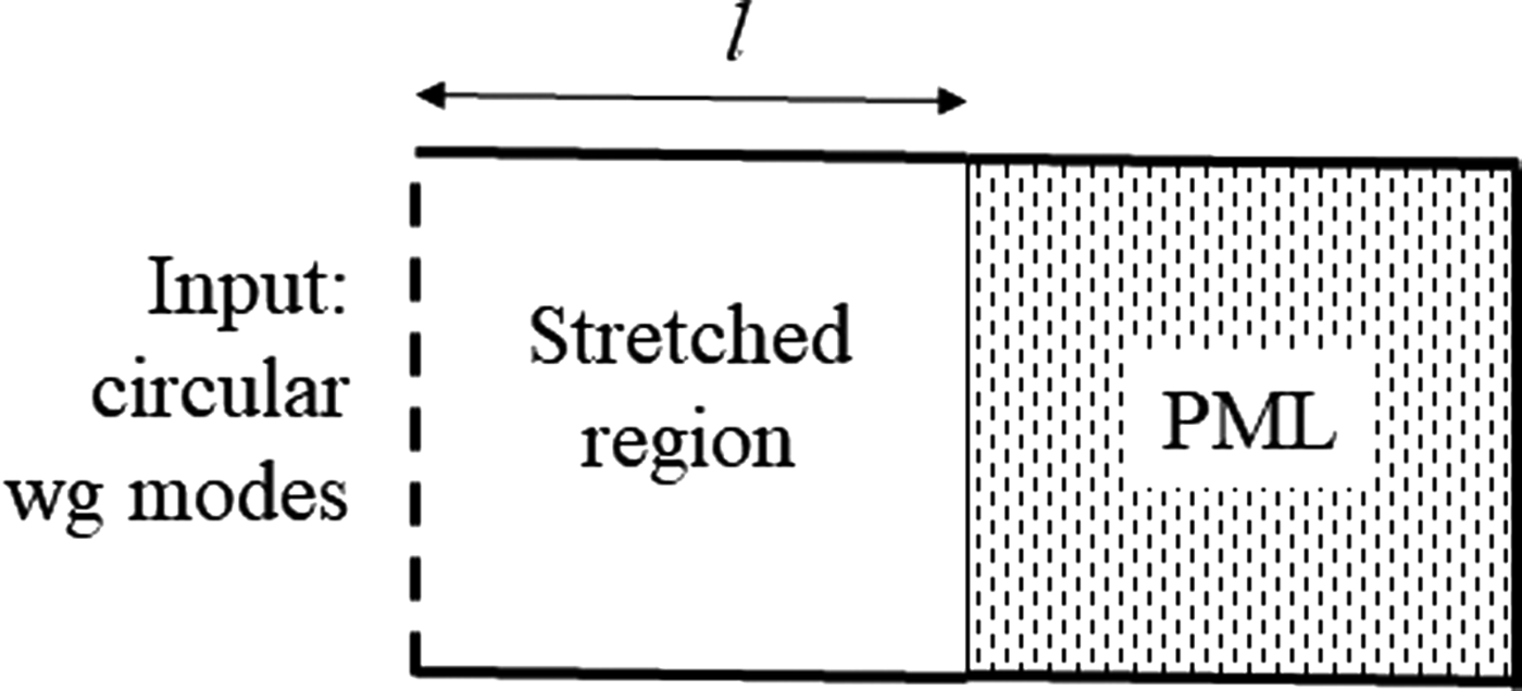
In this work we now describe this second possibility. Deembedding requires to compute the impedance matrix of a section of finite length l of non-reflecting elliptical waveguide (represented by its equivalent anisotropic CWG). This can be obtained by loading a straight waveguide section with PML (see Fig. 1). Let Zg be the impedance matrix for this structure computed for a set of isotropic CWG TE/TM modes. Zg is a full matrix with non-zero off diagonal elements representing coupling between isotropic CWG modes with varying azimuthal index m and radial index n. These modes form a base for the expansion of any field and they are therefore used to represent modes in the anisotropic CWG. The coefficients of these expansions are obtained as follows: since the impedance matrix of the same structure computed for the modes of the anisotropic CWG is diagonal (being a non-reflecting structure), one finds the expansion coefficients by diagonalizing matrix Zg. Doing so, one obtains a set of eigenvalues and eigenvectors and these latter contain the coefficients of the expansion of each mode of the anisotropic CWG into modes of the isotropic CWG. This same expansion is then used to convert the multimode impedance matrix of the original horn/structure, obtained with (40), to that of the anisotropic CWG and finally to obtain the multimode scattering matrix for the anisotropic CWG. In more detail, starting from
 $${\bf V} = {\bf Z}_g{\bf I}$$
we look for a linear combination of the voltages and currents
 $${\bf V}' = {\bf M}{\bf V}, \quad{\bf I}'={\bf M}{\bf I}$$
such that the new impedance matrix is diagonal
 $${\bf V}' = {\bf Z}'_g{\bf I}'.$$
By substitution we get
 $${\bf Z}'_g = {\bf M}{\bf Z}_g{\bf M}^{-1},$$
obtained by the eigenvalues/eigenvectors decomposition of Zg. The columns of matrix M contain the coefficients of the expansion of each mode in the anisotropic CWG into modes of the isotropic CWG. The final result, i.e. the generalized scattering matrix S for the set of anisotropic CWG modes (S of “voltage” type) is obtained as
 $${\bf S} = {\bf Z}'_g({\bf Z}'+ {\bf Z}'_g)^{-1}({\bf Z}' - {\bf Z}'_g){\bf Y}'_g$$
where Y′g = (Z′g)−1 and
 $${\bf Z}' = {\bf M}{\bf Z}{\bf M}^{-1}.$$
After some simplifications one finds
 $${\bf S} = {\bf M}{\bf Z}_g({\bf Z}+ {\bf Z}_g)^{-1}({\bf Z} - {\bf Z}_g){\bf Y}_g{\bf M}^{-1}$$
being  ${\bf Y}_g = {\bf Z}_g^{-1}$.
Structure analyzed for deembedding purposes.

Radiation
Open structures require the computation of the radiated fields. These can be obtained for the structure by the equivalence theorem [Reference Love19]. Letting e, h be the fields obtained by solving the BoR-FEM problem and letting e′, h′ the fields in the original structure, we have
 $$ {\bf e}' = {\bf J}^{\rm T}{\bf e}$$
 $$ {\bf h}' = {\bf J}^{\rm T}{\bf h}$$
whereas points in the transformed domain x, y, z correspond to x′ = s x, y′ = y, z′ = z. The equivalent electric and magnetic surface currents j′s and m′s in the original frame are therefore
 $$ {\bf j}'_s = {\bf n}'\times{\bf h}'$$
 $$ {\bf m}'_s = -{\bf n}'\times{\bf e}',$$
where we have introduced the normal unit vector in the original domain, n′, defined as
 $${\bf n}' = \displaystyle{{{\bf J}^{\rm T}{\bf n}}\over{\vert{\bf J}^{\rm T}{\bf n}\vert}}.$$
Results
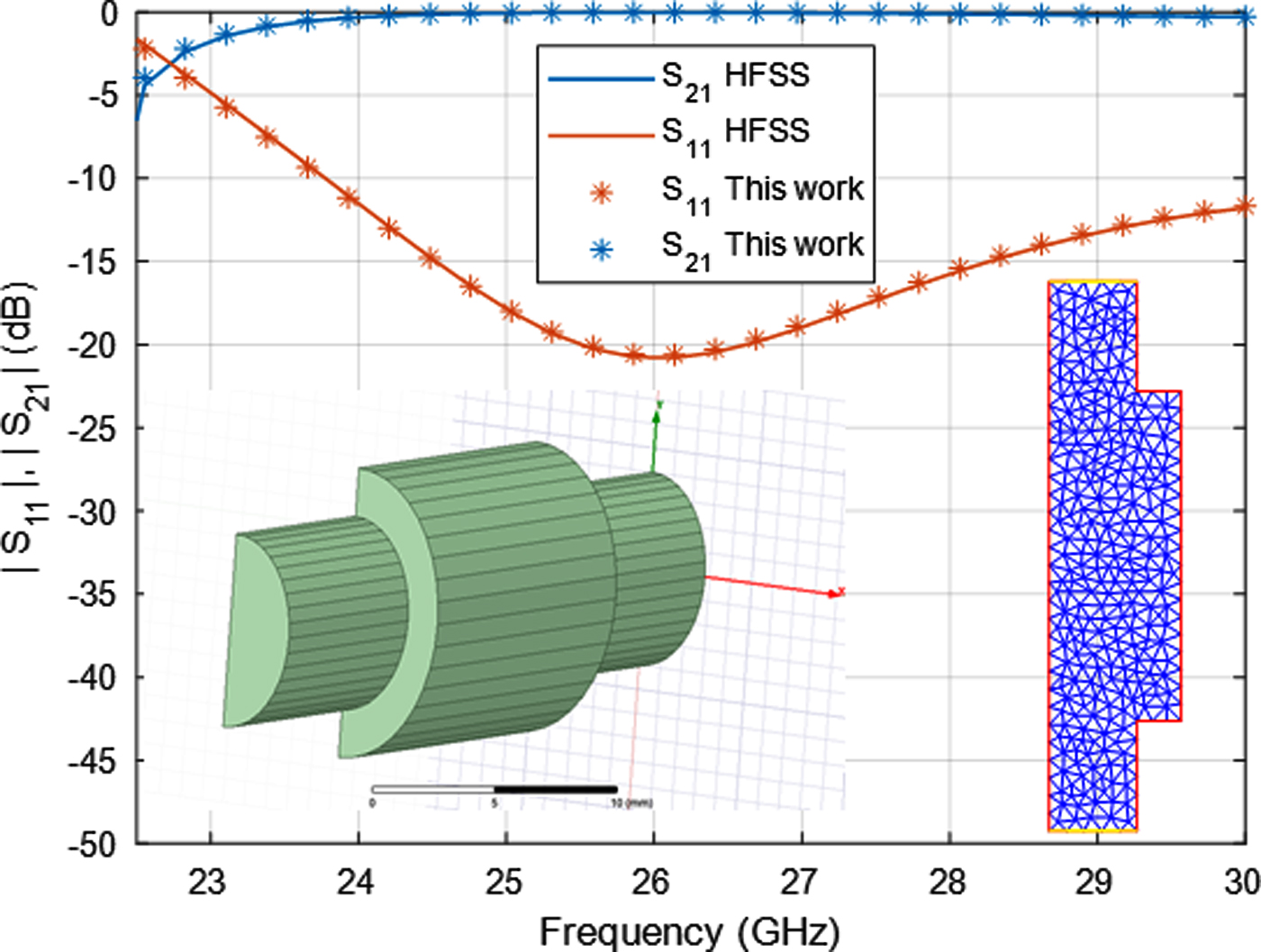
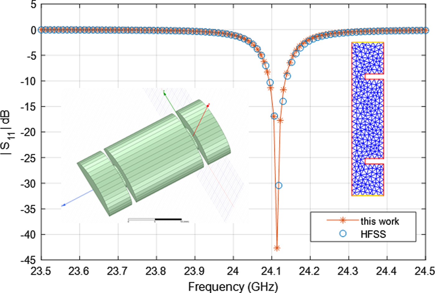
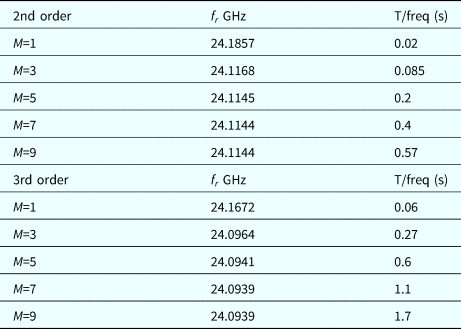
We show now some results on the application of the method described in this paper. The numerical performance of the BoR-FEM depends mainly on the mesh density, the polynomial degree of the elements and the maximum harmonic index M. As first examples we show two closed structures. The first one is a cascaded double step with a larger internal waveguide (Fig. 2, the physical dimensions are described in the caption). For this structure we made a comparison with HFSS, and an excellent agreement is observed. The 2D mesh used for the analysis is also shown in the figure. Using M=3, the analysis took 0.1 s/freq. The second structure is a resonator, defined by two irises in elliptical waveguide (Fig. 3). Also in this case the physical dimensions are given in the figure caption. This can be the basis for a filter in elliptical waveguide and is also a good benchmark for accuracy and efficiency computation. Also in this case the comparison with HFSS is excellent, but it was necessary to push the accuracy of HFSS to very high levels. We also had to use many segments to describe the ellipses. In order to test the performance of the method, we show in Table 1 the effect of the maximum harmonic index M on both the resonant frequency and the CPU time. About this latter, times refer to a Matlab implementation and great improvements are possible using parallelization and a compiled code. Times refer to a PC with Intel i7 processor. In the table, both 2nd order and 3rd order BoR-FEM elements results are shown and the mesh did not change in all computations (the mesh is also shown in the figure). Note that 2nd order elements with M=3 provide a very good accuracy with just 0.085 s/freq. For comparison, using HFSS we obtained a value f r = 24.0955 GHz with about 4 s/freq. As a comparison, a similar accuracy with the proposed technique is obtained with M=3 and 3rd order elements, with about 0.3 s/freq.
Scattering parameters of cascaded step discontinuities in elliptical waveguide. Input waveguide: b = 4 mm4, a=2.8 mm (s=0.7), internal waveguide :b=6 mm4, a = 4.2 mm, internal length 15 mm. In the figure the 2D mesh used in the analysis is also shown.

Scattering parameters of resonator in elliptical waveguide. Input waveguide: b = 6 mm, a = 3 mm (s=0.5), internal waveguide: b = 2.5 mm, a = 1.25 mm, internal length 15 mm, iris thickness 1 mm.

CPU time and convergence of resonant frequency for the structure in Fig. 3. M = maximum harmonic index. BoR-FEM: 2nd order elements and 3rd order elements

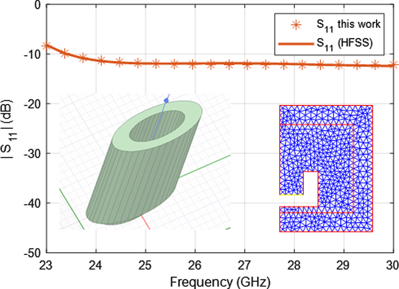
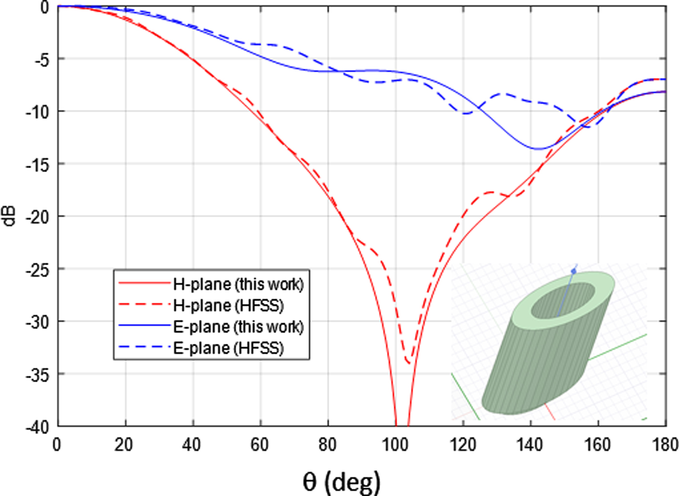
The next example is an open-ended elliptical waveguide and is shown in Fig. 4. The waveguide has b = 4 mm, a = 1.6 mm (s=0.4) and, because of the transformation, the metal around the opening is 2.5 mm thick in the y direction and 1 mm in the x direction. Again, we used HFSS for validation. As shown in the figure, there is an excellent agreement between our code and HFSS, but our simulation runs in few seconds. The radiation patterns of the structure in the principal planes are shown in Fig. 5. The reference curve by HFSS has some oscillations because of the imperfect behavior of radiation boundaries, but the agreement is good. These results have been obtained with M=5.
Reflection coefficient of a truncated elliptical waveguide of semiaxes b = 4 mm, a = 1.6 mm (s=0.4). The metal around the waveguide is 2.5 mm thick along y and 1 mm thick along x. In the figure the 2D mesh used in the analysis is also shown.

E- and H-plane radiation patterns of the truncated elliptical waveguide in Fig. 4 at 27 GHz.

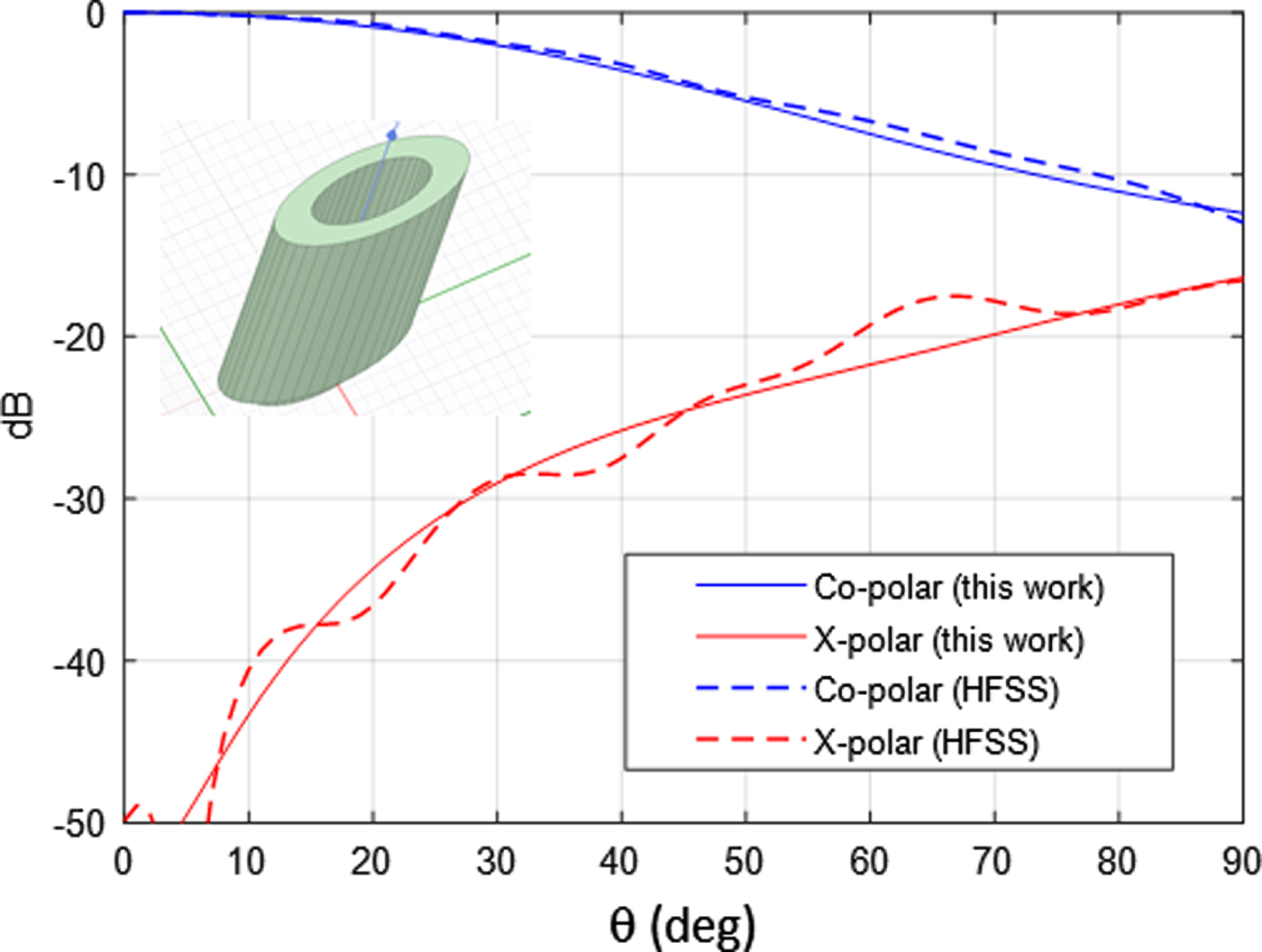
In Fig. 6 we show a comparison for Co-polar and X-polar patterns for the same structure in the ϕ = 45° plane. Also in this case the agreement is very good, indicating very good performance of the PML.
Co-polar and X-polar radiation patterns of the truncated elliptical waveguide in Fig. 4 in plane ϕ = 45° at 27 GHz.

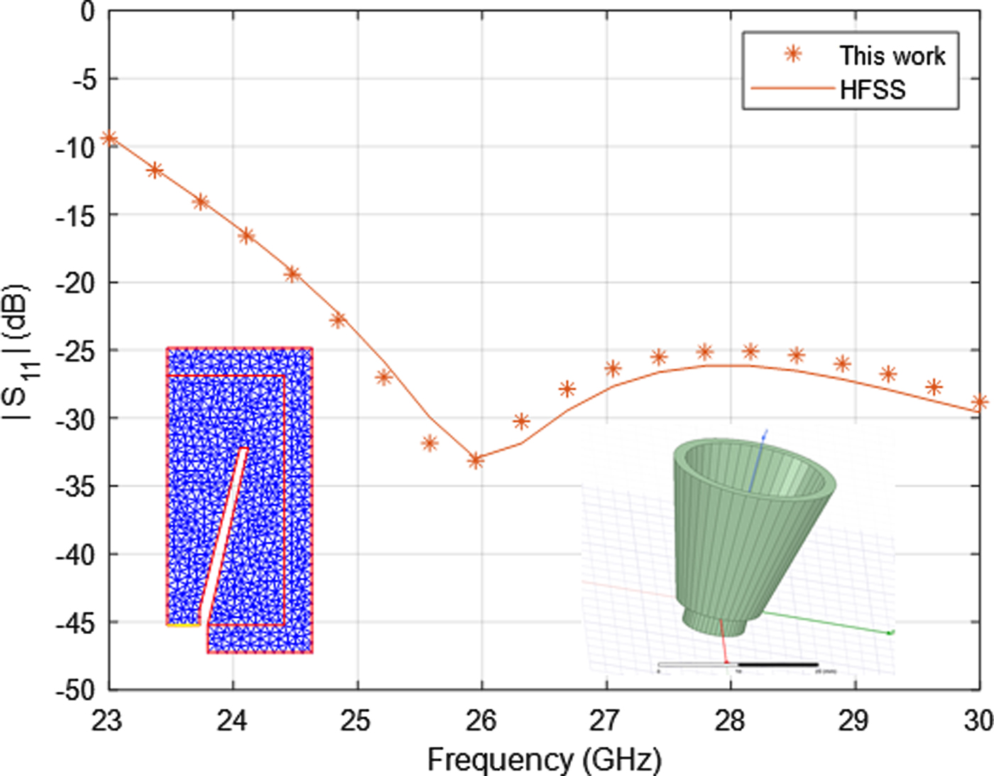
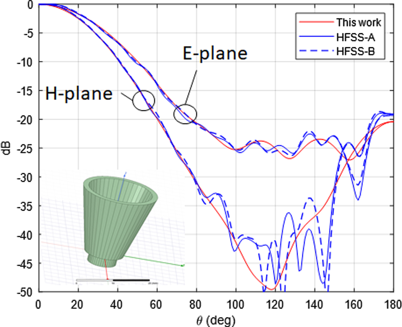
Finally, in Fig. 7–8 the results refer to an elliptical horn (physical dimensions in the caption). The axial ratio is 0.67 and the CPU time for this case is less than 1 s/freq with a maximum harmonic index M=5. In general, convergence of S 11 is obtained with rather low values of M, but the radiation patterns are more sensitive with respect to M. There is a clear dependence of M on the axial ratio, but even for ratios as high as 3 we got very good results with M=9. Note that as a result of the transformation, the outer wall thickness is not constant around the horn circumference. For the horn analyzed, it is t = 1 mm along y and t = 0.67 mm along x. The simulation with HFSS for this case is labeled as HFSS-A. In order to show that this effect is not of major concern, we also show the simulation with t = 1 mm constant along the horn circumference (HFSS-B). In general we obtained time savings ranging from 1 to 2 orders of magnitude with respect to HFSS and these are clearly due to the greatly improved representation of the electromagnetic field in the BoR-FEM analysis.
Reflection coefficient of an elliptical horn with axial ratio 0.67. Input waveguide a = 2.7 mm b = 4 mm. Output aperture a = 6.03 mm, b = 9 mm. Length 20 mm. Metal thickness along y 1 mm.

Radiation patterns at 25.8 GHz for the horn in Fig. 7. HFSS-A refers to the actual horn, HFSS-B to an identical horn except for the thickness of the outer wall, which is t = 1 mm constant around the horn circumference.

Conclusions
A new powerful method for the analysis of elliptical structures with constant axial ratio is shown. The method is based on 2.5D FEM and TO. Because of the particular sparse matrix structure, excellent efficiency and accuracy are obtained. Validation is shown for elliptical cascaded step discontinuities and radiation from elliptical horns.
Author ORCIDs
G. G. Gentili, 0000-0001-9533-8458 and S. Selleri, 0000-0003-3090-1451
 Gian Guido Gentili was born in Turin, Italy, in 1961. He received the Laurea degree in electronics engineering from the Politecnico di Milano, Milan, Italy, in 1987. He joined as a Researcher with the Dipartimento di Elettronica ed Informazione, National Research Council (CNR), Center for Space Telecommunications, Politecnico di Milano, in 1989. In 2001, he became a Senior CNR Researcher. He became an Associate Professor with the Politecnico di Milano in 2002. He wasa VisitingScholar at Politecnica de Madrid in 1993 and 1995. He is responsible for the Electromagnetics Laboratory of Politecnico di Milano ‘Wavelab’. His research interests include numerical method for electromagnetics (finite elements, method of moments, and mode-matching), antennas and feed systems for terrestrial and space applications, microwave passive devices and filters, plasmonics, and terahertz radiation.
 Misagh Khosronejad was born in Ghorveh, Iran, in 1989. He received the B.Sc. degree in electrical engineering-telecommunication from Khajeh Nasir Toosi University of Technology, Tehran, Iran, in 2011, and the M.Sc. and Ph.D. degrees in telecommunication engineering from Politecnico di Milano, Milan, Italy, in 2014 and 2017, respectively. From 2009 to 2012, he was with Advanced Electromagnetic Laboratory at KNTU, Tehran, Iran. Since 2013, he has been a Research Fellow in applied electromagnetic group at Politecnico di Milano. His research interests includeantennas, microwave circuits, radar communication, numerical andcomputational electromagnetic (CEM).
 Giuseppe Pelosi (M'8-SM'91-F'00) was born in Pisa, Italy, in 1952. He received the Laurea (Doctor) degree in physics (summa cum laude) from the University of Florence, Florence, Italy, in 1976. He is currently with the Department of Information Engineering of the same university, where he isa Full Professor of Electromagnetic Fields. He was a Visiting Scientist at McGill University, Montreal, Quebec, Canada, from 1993 to 1995, and a Professor at the University of Nice-Sophie Antipolis, France, in 2001. He wasa coauthor of several scientific publications on the aforementioned topics, appeared in international refereed journals, and national and international conferences. He has beena guest editor of several special issues of international journals: IEEE Antennas and Propagation Magazine, 2013 (with Y. Rahmat-Samii and J.L. Volakis); IEEE Transactions on Antennas and Propagation, 2001 (with V. Grikunov and J.L. Volakis); International Journal of Numerical Modelling: Electronic Networks, Devices and Fields, 2000 (with P. Guillon and T. Itoh); Electromagnetics, 1998 (with J.L. Volakis); Annales des Telecommunications (with J.L. Bernard and P.Y. Ufimtsev), 1995; COMPEL, 1994 (with P.P. Silvester); COMPEL, 2002; Alta Frequenza-Rivista di Elettronica, 1992. He is alsoa coauthor of three books: Finite Elements for Wave Electromagnetics (with P.P. Silvester, IEEE Press, 1994), Finite Element Software for Microwave Engineering (with T. Itoh and P.P. Silvester, Wiley, 1996), and Quick Finite Elements for Electromagnetic Fields (with R. Coccioli and S. Selleri, Artech House, 1998 and 2009). With P.P. Silvester (McGill University), he wasa promoter of the International Workshop on Finite Elements for Microwave Engineering. This workshop is held every 2 years, and is the meeting point for finite-element researchers from all over the world. He is also active in the history of the telecommunications engineering field. He has been an Associate Editor for the Historical Corner of the IEEE Antennas and Propagation Magazine since 2006. Among his latest publications in this field is the book, A Wireless World. One Hundred Years Since the Nobel Prize to Guglielmo Marconi (series contribution to the History of the Royal Swedish Academy of Sciences, 2012). His research activity is mainly focused on numerical techniques for applied electromagnetics (antennas, circuits, microwave and millimeter-wave devices, scattering problems). Dr. Pelosi has been a member of the Board of Directors of the Applied Computational Electromagnetics Society (ACES) (1999–2001), of the Board of Directors of the IEEE Central and South Italy Section (1992–1995 and 1995–1998), and Chair of the IEEE Magnetics Chapter of the same Section (1996–1999).
 Stefano Selleri (S'92-M'96-SM'03) was born in Viareggio, Italy, on December 9, 1968. He received the Laurea degree (with honors) in electronic engineering and the Ph.D. degree in computer science and telecommunications from the University of Florence, Florence, Italy, in 1992 and 1997, respectively. In 1992 he was a Visiting Scholar at the University of Michigan, Ann Arbor, MI; in 1994 at the McGill University, Montreal, Canada; in 1997 at the Laboratoire d'Electronique of the University of Nice-Sophia Antipolis. From February to July 1998 he was a Research Engineer at the Centre National d'Etudes Telecommunications (CNET) France Telecom. He is currently an Associate Professor at the University of Florence, where he conducts research on numerical modeling of microwave, devices, and circuits with particular attention to numerical optimization. Since September 2006, he is an Associate Editor of the International Journal of Antennas and Propagation.