I. INTRODUCTION
With great success in portable electric devices, lithium ion batteries (LIBs) have been considered as the most promising energy storage devices.Reference Scrosati1–Reference Chung, Bloking and Chiang3 However, there are persistent demands for batteries with higher power density and longer cycling life to power newly emerging devices. Among the various cathode materials being evaluated for high-power, high-performance LIBs such as lithium-cobalt oxide (LCO), lithium-manganese oxide (LMO), lithium-iron phosphate (LFP), lithium-nickel-manganese-cobalt oxide (NMC), and lithium nickel-cobalt-aluminum oxide (LCA), the cathode material lithium manganese oxide (LiMn2O4), also known as LMO, is one of the most promising candidates due to its low cost, environmental friendliness, and abundant availability.Reference Li, Dahn and Wainwright4–Reference Thackeray, Johnson, Depicciotto, Bruce and Goodenough6 In spite of LiMn2O4 having many merits, its power performance and cycling stability are often hampered by problems of large polarization and capacity decay especially under large currents.Reference Thackeray7–Reference Tang, Tian, Liu, Li, Zhang, Yue, Bai, Wu and Zhu9 The large polarization is generally considered to be due to sluggish Li+ diffusion in bulk electrode, and the capacity decay often results from manganese (Mn) dissolution or structure transformation.Reference Wang and Cao10–Reference Ding, Xie, Cao, Zhu, Yu and Zhao12 To overcome the demerits, various strategies have been implemented such as: (i) decreasing the particle size to nanoscale, (ii) resorting to surface coating and (iii) cations doping. However, surface coating and cations doping are at the expense of yieldable capacity.Reference Fu, Zhang, Cao, Zhang and Wu13,Reference Lytle, Yan, Ergang, Smyrl and Stein14 Compared with the bulk counterpart, the nanoscaled electrode materials can shorten Li+ diffusion distance and facilitate faster Li+ migration, resulting in better high-rate performance.Reference Hosono, Kudo, Honma, Matsuda and Zhou15,Reference Ding, Xie, Cao, Zhu, Yu and Zhao16 Hence, design and synthesis of nanosized cathodes can be a very efficient solution.
Recently, great attention has been paid to the electrode materials with secondary architecture built by primary nanoblocks. The hierarchical structure will enhance the electrode/electrolyte contact area, shorten the Li+ diffusion length; the void space between neighboring nanoblocks allows easy diffusion of the electrolyte; and secondary architecture built by primary nanoblocks can buffer strain from volume variation during Li insertion/extraction.Reference Hu, Zhong, Zheng, Huang, Zhang and Chen17 For example, the composite of Sn/C (tin nanoparticles as encapsulated in elastic hollow carbon spheres) exhibits a capacity of over 550 mAh/g after 100 cycles.Reference Zhang, Hu, Guo, Zheng, Zhong, Song and Wan18 Lee et al.Reference Lee, Kim and Song19 reported the hollow sphere built upon by lithium iron phosphate, also known as LFP, nanoparticles (C/LiFePO4) with a secondary architecture built by primary nanoblocks and improved electrochemical performance. Deng et al.Reference Deng and Lee20 have reported that core-shelled mesospheres of SnO2 nanoparticles could exhibit a high Li-storage capacity.
In this work, we prepared LiMn2O4 microspheres secondary structure of nanoparticles/plates via a facile template-support reaction. To our knowledge, there are no reports on the synthesis of the LiMn2O4 with this secondary structure as cathodes for LIBs. The material may have some structural advantages for the application in LIBs. First, primary nanoblocks in this structure can process fast Li+ insertion/extraction due to reduced diffusion distance, which may result in improved rate capability. Additionally, the secondary structure can buffer the volume changes and keep in tact structural stability during cycling, displaying improved cycling performance. As expected, compared with the solid counterpart, the sample with secondary structure displays remarkably improved performance in terms of high discharge capacity, excellent rate capability and long cycling life.
II. EXPERIMENTAL
All the chemicals were used without further purification. Manganese carbonate (MnCO3) microspheres were prepared by the precipitation method.Reference Fei, Cui, Yan, Qi, Yang, Wang, He and Li21 Manganese sulfate (MnSO4) (4 mmol) was dissolved in 200 mL of distilled water. Then, 40 mL of ethanol was added in the above solution under stirring. In the successive step, 200 mL of ammonium bicarbonate (NH4HCO3) solution (0.2 M) was slowly dropped into the mixed solution under stirring. After the reaction, the white precipitate was collected, washed with distilled water and ethanol repeatedly and dried at 50 °C under vacuum for 12 h. The LiMn2O4 microspheres secondary structure of nanoparticles/plates (CSPMS-LMO) was prepared as follows: first, the obtained MnCO3 microspheres were precalcined at 500 °C for 4 h to form hierarchical Mn2O3; second, MnO2 microspheres secondary structure of nanoparticles/plates (CSPMS-MO) were obtained by etching Mn2O3 with 0.45 M HCl; finally, CSPMS-LMO was prepared by calcining CSPMS-MO with LiOH at 700 °C for 8 h in air. For comparison, solid LiMn2O4 microspheres (SM-LMO) were also prepared by the same solid-state reaction using the prepared MnCO3 and LiOH as precursors.
The crystalline structure of the samples was characterized by x-ray diffraction on (XRD; Rigaku model No. D/Max-2550pc, Rigaku Industrial Corporation, Osaka, Japan) powder diffractometer. The chemical compositions of the product were determined by inductively coupled plasma-atomic emission spectrometry (ICP-AES; IRIS Intrepid II XSP, Thermo Electron Corporation, Waltham, MA). The morphologies were observed by on (FESEM; FEI-sirion microscope) and transmission electron microscopy on a microscope (TEM; model No. JEM 2100F, JEOL Ltd., Tokyo, Japan). The specific surface area of the products was determined by the Brunauer-Emmett-Teller (BET) method.
The electrochemical properties of the samples were evaluated with CR2025-type coin cells. The electrode slurry was made by blending 80 wt% active materials, 10 wt% acetylene black (AB) and 10 wt% polyvinylidene fluoride (PVDF) in N-methyl pyrrolidone (NMP). The slurry was then coated onto Al foil to make the working electrodes followed by drying at 80 °C under vacuum for 12 h. The cells were assembled in an argon-filled glove box using metallic Li foil as the counter electrode, 1 M lithium hexafluorophosphate (LiPF6) in ethylene carbonate (EC)-dimethyl carbonate (DMC) (1:1 in volume) as the electrolyte, and polypropylene microporous film (Celgard 2300, Celgard LLC Corporate, Charlotte, NC) as the separator. Galvanostatic charge/discharge was performed on a BTS battery tester (Neware, Shenzhen, China) in the voltage range of ∼3.5–4.3 V at various current densities. Cycle voltammetry (CV) tests were carried out on a CHI 660C electrochemistry workstation (Chenhua Instrument Co, Shanghai, China) at 0.1 mV/s.
III. RESULTS AND DISCUSSION
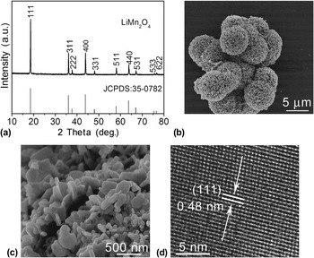
In Fig. 1(a), all the diffraction peaks of the product can be indexed to a cubic spinel phase of LiMn2O4 [Joint Committee on Powder Diffraction Standards (JCPDS) No. 35-0782]. No other additional peaks of possible impurities of Mn2O3 or Li2MnO3 are observed. Chemical composition of the product was further analyzed by ICP-AES. The result shows the atomic ratio of Li/Mn is 1.06:2. It displays the formation of lithium-rich spinel-type lithium manganese oxide phase and lithium may occupy some manganese sites (16c) in the spinel lattice.Reference Ding, Xie, Cao, Zhu, Yu and Zhao16 The microspheres have a diameter of around 7 μm [Fig. 1(b)]. Figure 1(c) displays further magnification image of the broken microsphere. We can observe that nanoparticles/plates are used as nanoblocks to assemble secondary microspheres. The product may have some structure advantages for LIBs. First, the secondary structure may provide a facile route of Li+ moving. Besides, the primary nanoplates/particles can short the distance of Li+ diffusion. Finally, the secondary microspheres may buffer volume variation and exhibit superior structure stability. From high-resolution transmission electron microscopy (HRTEM) image in Fig. 1(d), the measured d-spacing of 0.48 nm is consistent with that of (111) plane of LiMn2O4, confirming a good crystallization of the product.
(a) XRD pattern of as-synthesized LiMn2O4; morphology of the product: (b) low-magnification SEM image, (c) high-magnification SEM images of a broken microsphere, (d) HRTEM image of a nanoplate.

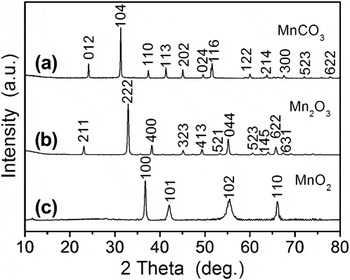
The formation of spinel LiMn2O4 includes four steps: the preparation of the precursor MnCO3, suitable precalcination, washing with HCl and high-temperature lithiation. From the XRD pattern in Fig. 2(a), the product obtained by the precipitation method can be indexed to single phase MnCO3 (JCPDS No. 44-1472). After precalcination at 500 °C for 4 h, all the diffraction peaks can be indexed to single Mn2O3, and no peaks of other phases such as MnCO3 or MnO2 are observed [Fig. 2(b)]. After washing Mn2O3 with 0.45 M HCl, typical peaks of hexagonal MnO2 are detected obviously, such as (100), (101), (110) and (102) peaks, consistent with JCPDS No. 30-0820 [Fig. 2(c)]. There are other obvious diffraction peaks that can be observed. From Figs. 2(b) and 2(c), we can see that the transformation from Mn2O3 into MnO2 occur by washing Mn2O3 with HCl. It is suggested that the disproportionation reaction (2Mn3+→Mn2+ + Mn4+) may take place during washing with HCl. The product MnO may preferentially dissolve into HCl. But it is very difficult for MnO2 to dissolve into dilute HCl at room temperature. Therefore, the remaining solid product is MnO2 after washing Mn2O3 with HCl. Besides, to further confirm whether the transformation from Mn2O3 to MnO2 takes place, we calculated the weight loss of the solid after HCl etching. The weight loss of the solid is calculated to be 46%, related to the dissolution of MnO (45%). This can also confirm that the transformation from Mn2O3 to MnO2, in fact, did take place.
XRD patterns of (a) MnCO3 prepared by the precipitation method, (b) hierarchical Mn2O3 obtained after precalcination of MnCO3 at 500 °C for 4 h, (c) MnO2 obtained after etching Mn2O3 using 0.45 M HCl.

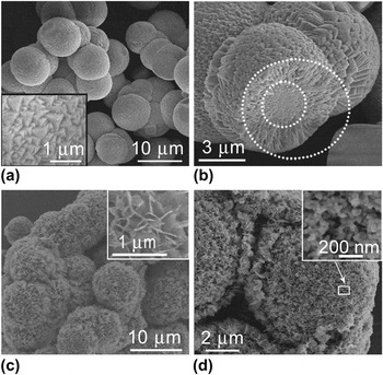
The uniform MnCO3 microspheres with the diameter of about 9 μm are formed during the precipitation reaction [Fig. 3(a)]. The surface of microspheres consists of nanopyramids [the inset in Fig. 3(a)]. In Fig. 3(b), solid microsphere exhibits different structures between inner core and outer shell. The inner core displays a closed-packed structure marked by an inner dotted circle, while the outer shell presents a radial structure marked by an outer dotted circle. Interestingly, after precalcination and washing, a three-dimensional microarchitecture is formed with nanoparticles/plates as primary nanoblocks. In Figs. 3(c) and 3(d), the diameter of MnO2 microspheres is around 7 μm, composed of nanoplates and nanoparticles. Upon precalcination, MnCO3 is oxidized to Mn2O3. In the successive step, we use diluted HCl to wash Mn2O3 microspheres. Mn3+ takes part in a disproportionation reaction (2Mn3+→Mn2+ + Mn4+). According to “Kirkendall effect,” movement of interface between diffusion couples (Mn2+/Mn4+) can contribute to the formation of primary nanoblocks.Reference Cao, Zhu, Shi, Zhu, Bao, Liu and Qian22 At the same time, MnO preferentially dissolves into HCl, while MnO2 forms the solid interface because it is difficult for MnO2 to dissolve into diluted HCl at room temperature. Therefore, we prepare the CSPMS-MO with nanoparticles/plates as primary nanoblocks. In the successive step, CSPMS-MO is used as self-support template and calcined with LiOH to obtain the target product LiMn2O4.
Morphology of (a) MnCO3 microspheres prepared by the precipitation method, the inset shows the outer surface of a microsphere, (b) a cross-sectional view of the broken MnCO3 microsphere, (c) MnO2 obtained after etching Mn2O3 with 0.45 M HCl, the inset shows the surface of the microsphere, (d) broken microspheres of MnO2, the inset shows the magnifying image of the section as marked by white pane.

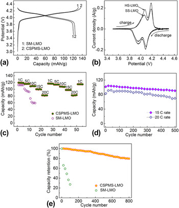
Coin-type cells were used to evaluate the electrochemical performance of LiMn2O4 samples (CSPMS-LMO and SM-LMO). Figure 4(a) displays the first charge/discharge curves of two samples at C/10 rate (1 C = 148 mA/g). Two plateaus are clearly seen in both samples, corresponding to the two-step Li-insertion/extraction mechanism.Reference Xia and Yoshio23 But CSPMS-LMO/Li cell displays the first discharge capacity of 126 mAh/g, slightly higher than that of SM-LMO/Li cell (119 mAh/g). It may be due to that the microspheres with secondary structure have larger surface area (18.3 m2/g), more than that of solid microspheres (3.8 m2/g). The large surface area can enhance active-material/electrolyte contact area and facilitate the redox reactions. From CV curves [Fig. 4(b)], two pairs of redox peaks are well defined, which agree well with the two pairs of potential plateaus in the charge/discharge curves. Remarkably, the peaks of CSPMS-LMO electrode are sharper than those of SM-LMO. This reveals higher crystalline of CSPMS-LMO. It also indicates superior reversibility of Li+ transport in its bulk and through its interface with the electrolyte.Reference Ding, Xie, Cao, Zhu, Yu and Zhao16
(a) The first charge/discharge curves of CSPMS-LMO and SM-LMO, (b) CV plots at 0.1 mV/s between 3.4 and 4.6 V, (c) the comparison of rate capability between CSPMS-LMO and SM-LMO, (d) discharge capacity as a function of cycle number for CSPMS-LMO electrode at different rates, (e) the comparison of cycling stability between CSPMS-LMO and SM-LMO at 10 C.

To explore power performance of the samples, rate capabilities of two samples were compared [Fig. 4(c)]. Obviously, CSPMS-LMO electrode displays rather better rate capability than SM-LMO electrode. The discharge capacity of CSPMS-LMO/Li cell can be recovered to 118 mAh/g when the current decreases from 20 to 1 C, indicating good reversibility. Although the discharge capacity decreases with increasing current density, the discharge capacities of 115 and 84 mAh/g are still retained at 10 and 20 C. Near 71% of its capacity can be preserved when the current increases from 1 to 20 C rate. The capacity loss can be explained by the ohmic drop and increased cell polarization at high current densities.Reference Hosono, Kudo, Honma, Matsuda and Zhou15 It is also suggested that the capacity loss observed on the increased rate is due to kinetic limitations, but not due to some structural changes of electrode materials. Our values are also higher than those of LiMn2O4 nanotubes (80 mAh/g at 10 C)Reference Ding, Xie, Cao, Zhu, Yu and Zhao16 and LiMn2O4 hollow microspheres (60 mAh/g at 3.4 C).Reference Xiao, Lu and Li24 It is hypothesized that the secondary microspheres may have more structural advantages when compared with that of nanotubes and hollow microspheres, such as higher electrochemical activity, easier penetration of the electrolyte and fast Li+ moving. The superior power performance of CSPMS-LMO can be attributed to its unique structure. First, the CSPMS-LMO can supply a large surface area due to assembled microarchitecture, which facilitates the redox reactions. Second, primary nanoblocks can shorten Li+ diffusion distance. It is beneficial for fast Li+ insertion/extraction and can result in good rate capability. When electrode material is discharged at 1, 5, and 10 C, the discharge capacities are 120, 115, and 110 mAh/g. Our values are higher than those of LiMn2O4 electrodes obtained by coprecipitation method (63 mAh/g at 3 C),Reference Naghash and Lee25 combustion reaction (73 mAh/g at 1 C),Reference Kovacheva, Gadjov, Petrov, Mandal, Lazarraga, Pascual, Amarilla, Rojas, Herrero and Rojo26 and hydrothermal method (117 mAh/g at 0.5 C).Reference Wu, Tu, Yuan, Chen, Xiang, Zhao and Cao27 The better electrochemical properties can be ascribed to template-engaged synthesis method, which can prepare the product with high crystallinity and secondary structure.
To investigate the high-rate cycleability of CSPMS-LMO, the material was discharged at 15 and 20 C after charging at 1 C rate [Fig. 4(e)]. The initial discharge capacities are 102 and 84 mAh/g. CSPMS-LMO electrode can still maintain discharge capacities of 91 and 70 mAh/g at 15 and 20 C after 500 cycles, revealing superior high-rate cycleability. It is suggested that microarchitecture built by nanoblocks can buffer the volume changes of the material upon repeated cycling, which is beneficial for sustaining structural stability and keeping high capacities even after 500 cycles.Reference Lee, Kim and Song19,Reference Zhou, Wu, Zhu and Lou28 To further distinguish this secondary-structure electrode and solid counterpart, the cycleability was further investigated both CSPMS-LMO and SM-LMO electrodes at 10 C discharge rate. It is apparent that the CSPMS-LMO electrode displays much better cycling stability compared with the SM-LMO electrode [Fig. 4(e)]. The capacity retention of 80% can be obtained after 800 cycles for CSPMS-LMO electrode. By contrast, the SM-LMO electrode can keep only 20% of its initial capacity after 100 cycles. Notably, CSPMS-LMO electrodes supply a better cycleablity in contrast with their solid counterpart. This is due to the fact that primary nanoblocks can shorten Li+ diffusion distance and facilitate rapid Li+ moving in the actives. This can decrease polarization during charge/discharge and result in superior cycling behavior.
IV. CONCLUSIONS
In summary, we succeeded in designing and synthesizing LiMn2O4 microspheres secondary structure of nanoparticles/plates by a template-engaged method. As cathodes for LIBs, the product shows much improved rate capability and cycling life in contrast to their solid counterpart. The remarkably enhanced performance can be ascribed to the secondary structure of the product, which is beneficial for fast Li-insertion/extraction and buffering the volume expansion/contraction upon cycling. In view of facile fabrication and improved performance, this material shows a promising application as cathodes for LIBs aiming for high-power applications.
ACKNOWLEDGMENTS
The authors appreciate the support from National Basic Research Program of China (Grant No. 2013CB934001), the National Natural Science Foundation of China (Grant No. 51101139), the Ph.D. Programs Foundation of Ministry of Education of China (Grant No. 20100101120024), the Qianjiang Talents Project of Science Technology Department of Zhejiang Province (Grant No. 2011R10021), and Key Science and Technology Innovation Team of Zhejiang Province under Grant No. 2010R50013.