1. Introduction
The basic method of accumulation and heating of a high-temperature plasma confined in a magnetic field is the injection of powerful beams of neutral atoms. Thus, the development of highly efficient sources of such beams is an integral part of the fusion problem. In order to form atomic beams with energy exceeding 0.5 MeV, it is necessary to accelerate negative ions up to a specified energy and pass them through a neutralizing target. High neutralization efficiency is required to increase the ratio of the energy yielded in a reactor to that consumed. This is of particular importance for reactions with a low energy yield. At the Budker Institute of Nuclear Physics (BINP), a low-temperature plasma was proposed as a neutralizing target (Dimov & Roslyakov Reference Dimov and Roslyakov1975). The relative yield of atoms in a plasma target is much higher than that in gas targets: up to 85 % as compared with 55 %.
In this paper a plasma target trap under development at the BINP is considered. For a detailed study of plasma dynamics and its confinement efficiency, both laboratory experiments and numerical simulation are necessary.
2. Plasma target trap
For neutralization of the round beam of negative ions, the target plasma should be shaped as a long cylinder about 10 cm in diameter. This column of plasma must be confined within a magnetic trap having wide-aperture holes at its ends for the passage of a neutralized beam. Plasma confinement is complicated, because the magnetic field should suppress plasma instabilities but allow only small plasma loss. Prevention of significant plasma outflow through the holes is especially important, for otherwise an extremely productive pumping system will be required. Loss of plasma at the walls of the trap is less significant since it causes only an increase in gas ionization power, due to plasma reflection from the chamber walls as a gas.
At the BINP an axisymmetric magnetic trap has been proposed (Dimov & Ivanov Reference Dimov and Ivanov2013), with a weak longitudinal field in the main volume of the trap and inverse mirrors in the holes (with the opposite direction of the longitudinal field). If, for particles of charge
 $q$
in inverse mirrors, the second term of the generalized momentum
 $$\begin{eqnarray}p_{{\it\varphi}}=mr^{2}\dot{{\it\varphi}}+\frac{q}{2{\rm\pi}c}{\it\Phi}\end{eqnarray}$$
is much bigger than the first term, longitudinal confinement of particles will be very hard because of conservation of generalized momentum in an axially symmetric system. It is possible to limit plasma loss at the trap walls with multipole magnetic walls, which are formed by a sequence of annular magnets with variable magnetization.
There is neither an azimuthal component of the magnetic field nor a stationary azimuthal electric field in the axisymmetric trap with annular magnetic surfaces. As a result, a stationary plasma drift in crossed fields that is normal to the walls cannot arise in such a trap. Consequently, and because of the natural magnetohydrodynamic stability of the plasma surrounded by multipole walls, plasma electrons are well confined. As a result, the plasma potential is reduced and plasma ions are better confined.
The effectiveness of the proposed magnetic system was confirmed by testing the prototype trap (Dimov & Emelev Reference Dimov and Emelev2014). A hard restriction of plasma outflow through an end hole with an inverse mirror has been experimentally demonstrated and the mechanism of this restriction has been shown. It is proved that electrons are confined within the trap predominantly by magnetic fields. A stepwise decrease of plasma density in the region of an inverse mirror was observed, along with a sharp decrease along the radius. This confirms high efficiency plasma confinement in the trap.
At present a plasma target trap for neutralization of negative ion beams is being developed at the BINP. The trap is a cylindrical system with a vacuum chamber of inner diameter 199 mm (figure 1). The total length of the trap is 1355 mm. The trap consists of a central cathode block and two mirror-symmetric cylindrical sections and end holes. Additional separation of each of the cylindrical sections into two halves is due to mechanical resistance.
Sketch of the target trap: 1, wide aperture holes for the passage of a neutralized beam; 2, cathode block; 3, one of the six cathodes; 4, permanent magnets; 5, magnetic yoke.

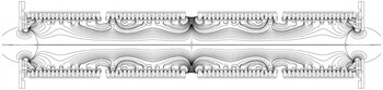
Sketch of the trap’s magnetic system and magnetic field lines.

Figure 2 shows a sketch of the trap’s magnetic system and magnetic field lines. The magnetic system consists of two mirror-symmetric halves. Radially and azimuthally magnetized NdFeB permanent magnets are placed alternately on the outer surface of a vacuum chamber with a wall thickness of 2.5 mm. This provides a sufficiently large field (up to 7 kG) near the surface of the chamber to ensure effective particle reflection. Magnetic yokes are placed above the magnets. The end magnetic assemblies, together with ring-shaped yokes, form inverse mirrors in the end holes, which are 10 cm in diameter. The system is cooled with distilled water flowing in four spiral channels.
Gas ionization is realized by electrons with energies of 100–150 eV. These electrons can be injected directly into the plasma from cathodes through the Debye layer. A central cathode block consists of six cathode packs that are installed uniformly along the circumference of the trap. Each unit has an 18 mm diameter
 $\text{LaB}_{6}$
cathode. The average density of the target plasma is assumed to reach
 $2\times 10^{13}~\text{cm}^{-3}$
particles at 70 % ionization. At these parameters the maximal yield of atoms is achieved (Dimov & Roslyakov Reference Dimov and Roslyakov1975). The composition of the hydrogen ions will be as follows:
 $\text{H}^{+}$
– 40 %,
 $\text{H}_{2}^{+}$
– 30 %,
 $\text{H}_{3}^{+}$
– 30 %. The electron temperature is assumed to reach 5 eV.
The trap has now been completely assembled. A set of devices for plasma diagnostics has been developed and constructed, including a diagnostic injector of hydrogen atoms and the diagnostic beam analyser. The ignition of the plasma in the trap has been implemented. For a more detailed analysis of plasma dynamics in the trap, the validation of measurements and optimization of the operating parameters of the trap, it is necessary to conduct mathematical modelling with the use of a suitable numerical model.
3. The mathematical model
Electrons are locked in the trap with a magnetic field, so in calculations it is important to take into account phase distribution, the region of loss and the region of confinement. Mathematical modelling is required to assess and minimize the loss of the plasma through the end holes (with inverse mirrors), as well as through the multipole magnetic walls of the trap to the surface of the vacuum chamber. Recall that the dynamics of plasma electrons can be described completely by the Boltzmann equation for distribution functions,
 $$\begin{eqnarray}\frac{\partial f_{{\it\alpha}}}{\partial t}+\boldsymbol{v}\frac{\partial f_{{\it\alpha}}}{\partial \boldsymbol{r}}+q_{{\it\alpha}}\left(\boldsymbol{E}+\frac{1}{c}[\boldsymbol{v},\boldsymbol{B}]\right)\frac{\partial f_{{\it\alpha}}}{\partial \boldsymbol{p}}=Stf_{{\it\alpha}},\end{eqnarray}$$
and the Maxwell equations with self-consistent electromagnetic fields (Vlasov Reference Vlasov1961),
 $$\begin{eqnarray}\displaystyle & \displaystyle \text{rot}\,\boldsymbol{B}=\frac{4{\rm\pi}}{c}\boldsymbol{j}+\frac{1}{c}\frac{\partial \boldsymbol{E}}{\partial t}=\frac{4{\rm\pi}}{c}\mathop{\sum }_{{\it\alpha}}q_{{\it\alpha}}\int f_{{\it\alpha}}\boldsymbol{v}\,\text{d}\boldsymbol{v}+\frac{1}{c}\frac{\partial \boldsymbol{E}}{\partial t}, & \displaystyle\end{eqnarray}$$
 $$\begin{eqnarray}\displaystyle & \displaystyle \text{rot}\,\boldsymbol{E}=-\frac{1}{c}\frac{\partial \boldsymbol{B}}{\partial t}, & \displaystyle\end{eqnarray}$$
 $$\begin{eqnarray}\displaystyle & \displaystyle \text{div}\,\boldsymbol{E}=4{\rm\pi}{\it\rho}=4{\rm\pi}\int f_{{\it\alpha}}\,\text{d}\boldsymbol{v}, & \displaystyle\end{eqnarray}$$
 $$\begin{eqnarray}\displaystyle & \displaystyle \text{div}\,\boldsymbol{B}=0. & \displaystyle\end{eqnarray}$$
 ${\it\alpha}$
denotes the type of particles (ions and electrons), whereas
 $Stf_{{\it\alpha}}$
is the function describing the following physical processes:
-
(i) ionization of the hydrogen atoms of the cathode electrons
 $\text{H}+\text{e}^{-}\rightarrow \text{H}^{+}+2\text{e}^{-}$
;
-
(ii) ionization of the hydrogen molecules of the cathode electrons
$\text{H}_{2}+\text{e}^{-}\rightarrow \text{H}_{2}^{+}+2\text{e}^{-}$
; -
(iii) ionization of the
$\text{H}^{+}$
ions and hydrogen atoms
$\text{H}_{2}+\text{H}^{+}\rightarrow \text{H}_{3}^{+}+\text{H}$
.


To solve this set of equations, a combination of the particle-in-cell method (Birdsall & Langdon Reference Birdsall and Langdon1985) and the Monte Carlo method is used. In order to describe the physical effects occurring in the entire trap volume with the accuracy required, it is necessary to use at least
 $10^{9}$
model particles and at least
 $10^{6}$
mesh nodes. Efficient equipment is required. Such demands on the model are caused by a complex configuration of the magnetic field, a multicomponent plasma, and, further, the necessity of taking into account the ionization of gas and plasma outflow from the trap.
Based on the splitting method, the solution of the Boltzmann equation is reduced to the solution of the Vlasov equation with the corresponding corrections of the particle trajectories with allowance for physical processes using the Monte Carlo method (Birdsall Reference Birdsall1991).
Since the target is cylindrical, we consider a two-dimensional formulation in cylindrical coordinates
 $R$
and
 $Z$
. Further, all three components of the fields and velocities of the particles (2D3V production) are taken into account. The motion of the particles takes place according to the characteristics of the Vlasov equation of the leapfrog scheme, for second-order accuracy. A local transformation from Cartesian to cylindrical coordinates is used to avoid singularities at the target axis; this is the scheme of Boris (Reference Boris1970).
The probability of collision of charged particles with neutral atoms is used to simulate ionization. Particles with the required parameters are added in the computational domain if a collision occurs.
The collision probability for the
 $j$
th particle possessing velocity
 $v_{j}$
for time
 ${\rm\Delta}t$
can be calculated on the basis of
 $$\begin{eqnarray}P_{j}=1-\text{exp}(-{\rm\Delta}s_{j}{\it\sigma}({\it\varepsilon}_{j})n_{j}(\boldsymbol{r}_{j})),\end{eqnarray}$$
(Vahedi & Surendra Reference Vahedi and Surendra1995), where
 ${\rm\Delta}s_{j}=v_{j}{\rm\Delta}t$
,
 ${\it\sigma}({\it\varepsilon}_{j})$
is the collision cross-section,
 ${\it\varepsilon}_{j}$
is the kinetic energy of the
 $j$
th particle, and
 $n_{j}$
is the local particle density of the corresponding type.
Obviously, collisions can be neglected until some time
 $T$
if
 $TN\max _{j}P_{j}\ll 1$
, where
 $N$
is the model number of electrons starting from the cathode in a single time step.
Thus the modelling process consists of two stages. In the first stage, up to time
 $T$
, the distribution of cathode electrons takes place in the trap; in the second stage of computing, from time
 $T$
, the effect of the collisions is recorded in full in accordance with (3.6). Variables
 $T$
and
 $N$
are chosen experimentally to distribute electrons across the entire target.
The initial conditions are as follows.
-
(i) Initial electron velocities are chosen according to the current from the cathode 150 A. The particles begin a radial movement towards the centre of the trap.
-
(ii) The particles are divided into five types: cathode electrons and plasma electrons with the corresponding energy and density, and ions
$\text{H}^{+}$
,
$\text{H}_{2}^{+}$
,
$\text{H}_{3}^{+}$
. -
(iii) The energy of the ions after collision corresponds to a temperature of 0.5 eV.
-
(iv) The electric field is zero; the magnetic field is equal to a predetermined magnetic field of the trap.


Boundary conditions: a particle crossing the border is considered to have left the trap.
To study the dynamics of some
 $10^{9}$
model particles, a parallel algorithm using a message passing interface (MPI) is used, based on the mixed Eulerian–Lagrangian decomposition (Berendeev et al.
Reference Berendeev, Ivanov, Lazareva and Snytnikov2013). The region of the solution is divided along the axis into several subregions. Then, particles in each subregion are uniformly distributed between processors of an individual group. The calculations were conducted using the following supercomputers: Lomonosov (Moscow State University), NKS-30T (Siberian Supercomputer Center, SB RAS) and the Cluster of Novosibirsk State University.
4. Results of the simulation
A spatial grid stepsize
 $h$
equal to or less than 0.1 mm is required in order to reproduce a magnetic field of the trap adequately. Thus, with a region size of
 $1355~\text{mm}\times 99.6~\text{mm}$
, a grid of
 $13\,550\times 996$
packs was chosen.
To reproduce a statistically correct process of ionization, up to
 $5\times 10^{9}$
model particles were used in calculations.
An important requirement for a chosen ionization method is the distribution of cathode electrons along the entire trap length. It is necessary to produce plasma having the required length. The cathode electron density was calculated (figure 3). It is seen that electrons are distributed up to the inverse mirrors. Waves of density, formed in the centre of the trap, are associated with the geometry of the magnetic field, since with a spiral motion the superposition of particle trajectories arises.
Density of cathode electrons at different time points after the start of ionization: (a)
 $2\times 10^{-7}~\text{s}$
, (b)
 $4\times 10^{-7}~\text{s}$
, (c)
 $8\times 10^{-7}~\text{s}$
, (d)
 $16\times 10^{-7}~\text{s}$
, (e)
 $24\times 10^{-7}~\text{s}$
;
 $n_{ek}=1.625\times 10^{10}~\text{cm}^{-3}$
.

Based on an obtained density of cathode electrons, the ion dynamics and the equilibrium density of plasma ions were calculated (figure 4). In order to provide efficient neutralization, the integral of the density of the plasma ions along the axial coordinate should be of a specified value regardless of the radial coordinate. The figure shows that the ions fill almost the entire target. The calculated value of this integral at the axis of the trap turns to be 25 % lower than its maximal value (at
 $R=35~\text{mm}$
). This degree of homogeneity is quite acceptable. The main plasma stream falls on the walls, with a small percentage going into the end holes.
Density of hydrogen ions
 $\text{H}^{+}$
in plasma,
 $n_{i}=572\times 10^{10}~\text{cm}^{-3}$
.

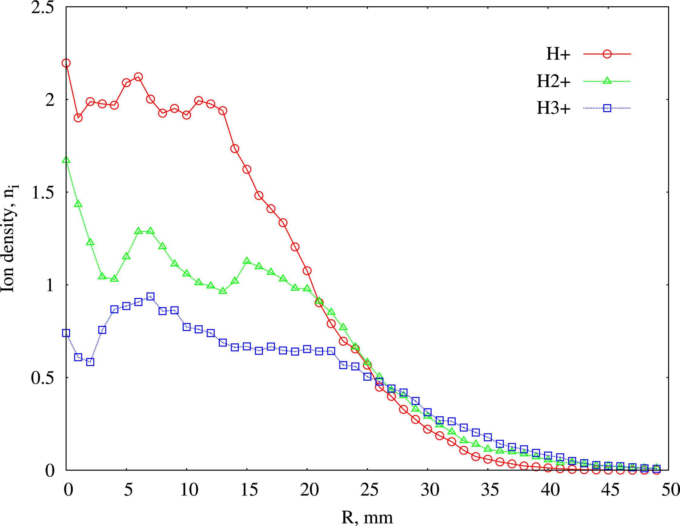
The radial distribution of ion density in the field of magnetic mirrors
 $(Z=1296~\text{mm})$
is shown in figure 5. As the figure shows, the ion density rapidly decreases along the radius, while the ions
 $\text{H}_{2}^{+}$
and
 $\text{H}_{3}^{+}$
are more spread out along the radius. However, with a radius of 25 mm the concentration of ions of different types is aligned and falls rapidly. This means that only particles with high transverse energy escape. A similar result was obtained experimentally by Dimov & Emelev (Reference Dimov and Emelev2014).
The radial ion density
 $\text{H}^{+}$
,
 $\text{H}_{2}^{+}$
,
 $\text{H}_{3}^{+}$
,
 $n_{i}=572\times 10^{10}~\text{cm}^{-3}$
(
 $Z=1296~\text{mm}$
).

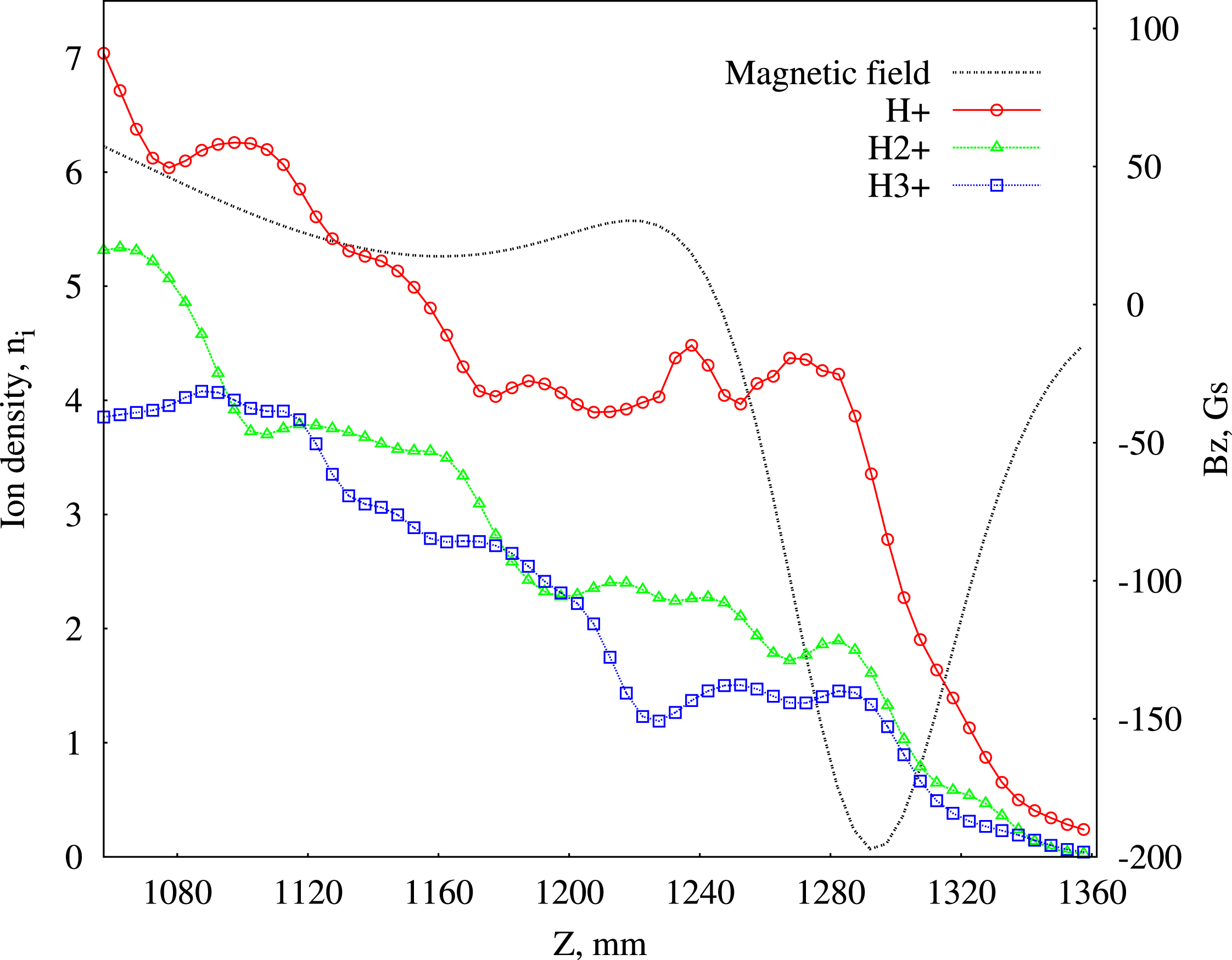
The results of calculations of plasma density on the axis in the field of a magnetic mirror are shown in figure 6. There is a stepwise decrease in the density of all of the ion components of the plasma along the axis in the region of the inverse magnetic mirror. This result is also fully consistent with the observations of Dimov & Emelev (Reference Dimov and Emelev2014). The estimated total ion current in an end hole was at most 0.5 A. Thus fairly good plasma confinement has been achieved. The plasma density achieved in the calculations amounted to more than
 $2\times 10^{13}~\text{cm}^{-3}$
as assumed to be achieved in the trap under development. This value of density was obtained at 150 A current of cathode electrons, which is quite possible in practice.
The density of the ions
 $\text{H}^{+}$
,
 $\text{H}_{2}^{+}$
,
 $\text{H}_{3}^{+}$
on the axis,
 $n_{i}=572\times 10^{10}~\text{cm}^{-3}$
and the distribution of the
 $Z$
-component of the magnetic field.

5. Conclusion
A plasma trap for highly efficient neutralization of powerful beams of negative ions has been developed and constructed; the plasma in the trap has been obtained. A magnetic system with a weak longitudinal field and inverse mirrors in end holes allows us to achieve sufficiently small plasma outflow from the trap.
For a detailed study of the trap, a mathematical model of the plasma has been developed, on the basis of a combination of the particle-in-cell method (Birdsall & Langdon Reference Birdsall and Langdon1985) and the Monte Carlo method. The model describes the confinement of a long plasma column in a magnetic field of complex geometry. The use of modern supercomputers has allowed us to calculate plasma dynamics, and to determine plasma streams both on the walls of the trap and through end holes. According to the results of the calculations, the generated plasma fills almost the entire length of the trap, has a diameter of about 10 cm and a density of about
 $10^{13}~\text{cm}^{-3}$
. The plasma outflow at the end holes is sufficiently small, and the plasma loss on the walls of the trap is negligible. Introducing the recombination cross-sections into the mathematical model will allow us to determine the plasma lifetime and the energy balance of the trap.
Before laboratory experiments, on the basis of a developed mathematical model, it was possible to make significant appraisals concerning the characteristics of the plasma trap. Mutual clarification of the results of simulation and the experiment, together with the optimization of the parameters of the trap to achieve its objectives, is scheduled in the future.
Acknowledgements
The development of numerical algorithms was supported by the Russian Scientific Fund, project 14-11-00485. Computational experiments were supported by the Russian Foundation for Basic Research, projects 14-01-31220, 14-01-00392, 15-01-00508.