I. INTRODUCTION
Micropillar compression, originally used for studying effects of size in metals,Reference Uchic, Dimiduk, Florando and Nix1–Reference Bei, Shim, George, Miller, Herbert and Pharr3 has the potential to be a technique for studying plastic flow in brittle materials at low temperatures as cracking may be suppressed without confining pressure or material.Reference Östlund, Howie, Ghisleni, Korte, Leifer, Clegg and Michler4–Reference Korte and Clegg7 Furthermore, by choosing the appropriate pillar orientation, individual slip systems can be interrogated,Reference Korte and Clegg7 whereas in indentation, multiple slip systems are always activated.Reference Lloyd, Molina-Aldareguia and Clegg8 This may not be important in metals where the deformation often requires only a single type of slip system, but in brittle materials with more complex structures, this is rarely the case.Reference Kelly, Groves and Kidd9 Here, the values of hardness tend to be associated with flow on the harder slip system.Reference Bouvier and Needleman10, Reference Gilman11 To make use of micropillar compression as a test technique, it is necessary to know how small a sample is required to suppress cracking. For this, the ways in which cracking can occur and the extent to which these are affected by scale need to be understood.
Although there have been a number of studies looking at micropillar compression of brittle crystalline materials,Reference Östlund, Howie, Ghisleni, Korte, Leifer, Clegg and Michler4–Reference Korte and Clegg7, Reference Korte and Clegg12, Reference Moser, Wasmer, Barbieri and Michler13 there have been few systematic studies of a size-dependent ductile–brittle transition. In studies of <100>-oriented micropillars of siliconReference Östlund, Rzepiejewska-Malyska, Leifer, Hale, Tang, Ballarini, Gerberich and Michler5 and gallium arsenide,Reference Östlund, Howie, Ghisleni, Korte, Leifer, Clegg and Michler4 cracking occurred predominantly by through-thickness axial splitting in pillars with diameters greater than about 0.3 and 2 μm for the silicon and gallium arsenide micropillars, respectively. At diameters less than these values, splitting was not observed, though Gerberich et al.Reference Deneen Nowak, Mook, Minor, Gerberich and Carter14–Reference Gerberich, Mook, Perrey, Carter, Baskes, Mukherjee, Gidwani, Heberlein, McMurry and Girshick16 have reported cracking in silicon spheres with diameters less than 100 nm, although there was extensive plastic flow even where cracking occurred in both the micropillarsReference Östlund, Howie, Ghisleni, Korte, Leifer, Clegg and Michler4, Reference Östlund, Rzepiejewska-Malyska, Leifer, Hale, Tang, Ballarini, Gerberich and Michler5 and the spheres.Reference Deneen, Mook, Minor, Gerberich and Carter15, Reference Gerberich, Mook, Perrey, Carter, Baskes, Mukherjee, Gidwani, Heberlein, McMurry and Girshick16
There are a number of ways in which size is known to influence cracking. For instance, as the size of the largest defect within a sample is limited by the sample size, decreasing this increases the strength in many geometries.Reference Griffith17 It has also been pointed out that there is a scale dependence, at least in certain loading situations, to the crack driving force itself.Reference Gurney and Hunt18–Reference Puttick20 Furthermore, there must also be a scale below which the K-field of the crack tip is larger than the sample size, so that one might expect such calculations to be invalid.
More recently, other work has indicated that the toughness, or fracture energy, may also increase with decreasing size.Reference Beaber, Nowak, Ugurlu, Mook, Girshick, Ballarini and Gerberich21, Reference Gerberich, Michler, Mook, Ghisleni, Östlund, Stauffer and Ballarini22 Based on pioneering work on grain-size effects in metals,Reference Huang and Gerberich23 it has been suggested that the increase in the yield stress at small scales allows an increase in the density of shielding dislocations at the crack tip and hence an increase in the material’s toughness.
Other effects are also possible. For instance, the leading partial of the glide dislocation in semiconductors tends to move more easily than the trailing partial.Reference Kelly, Groves and Kidd9 As the distance between these partials is less than the diameter of the micropillar, the possibility arises of a decrease in the flow stress and this has also been associated with a change in the fracture behavior.Reference Östlund, Rzepiejewska-Malyska, Leifer, Hale, Tang, Ballarini, Gerberich and Michler5
So far, cracking in micropillars has been observed to start at intersecting slip bands,Reference Östlund, Howie, Ghisleni, Korte, Leifer, Clegg and Michler4 as originally suggested by Cottrell.Reference Cottrell24 This gave the appearance of a sample being opened by the wedge of material initially above the slip plane.Reference Östlund, Howie, Ghisleni, Korte, Leifer, Clegg and Michler4, Reference Östlund, Rzepiejewska-Malyska, Leifer, Hale, Tang, Ballarini, Gerberich and Michler5 If a wedging geometry is assumed,Reference Östlund, Rzepiejewska-Malyska, Leifer, Hale, Tang, Ballarini, Gerberich and Michler5 then agreement with observations in silicon requires that the fracture toughness increases with decreasing sample size.Reference Östlund, Rzepiejewska-Malyska, Leifer, Hale, Tang, Ballarini, Gerberich and Michler5, Reference Beaber, Nowak, Ugurlu, Mook, Girshick, Ballarini and Gerberich21
In macroscopic experiments, brittle materials normally fail in compression by axial splittingReference Gordon25 and it has been suggested that a description on these lines might be more appropriate at the microscale as well. Such splitting is associated with preexisting defects where the compressive load causes the material on one side of the defect to shear over the other, nucleating an axial splitting crack from the tip of the preexisting defect.Reference Ashby and Sammis26 The slip plane may be considered as a defect as the effect of the compressive load is to shear the material on one side of the slip plane over the other, as in conventional splitting. By modifying a conventional splitting analysis, it was predicted that the stress intensity factor on the crack should decrease as the pillar size decreased, until, at a critical diameter, the stress intensity factor was less than the fracture toughness of the material so that cracking no longer occurred. Predictions of the theory were in good agreement with experiments on gallium arsenide.Reference Östlund, Howie, Ghisleni, Korte, Leifer, Clegg and Michler4
An increase in toughness might be considered as entirely equivalent to a decrease in the crack driving force. However the underlying mechanism, and therefore the scale dependence, may be very different. Furthermore, the suppression of one mode of cracking for whatever reason does not necessarily lead to all modes of cracking being suppressed. To investigate this in more detail, a range of materials—silicon, indium arsenide, magnesium oxide, and magnesium aluminate spinel—have been tested and compared with the previous observations on siliconReference Östlund, Rzepiejewska-Malyska, Leifer, Hale, Tang, Ballarini, Gerberich and Michler5 and gallium arsenide.Reference Östlund, Howie, Ghisleni, Korte, Leifer, Clegg and Michler4 The aim of this work is to see whether the splitting analysis holds for materials with different properties and slip crystallography and also what other modes of cracking occur and under what conditions each can take place.
II. EXPERIMENTAL
Micropillars were made by focused ion beam milling (Helios NanoLab, FEI Company, Eindhoven, Netherlands) with a final beam current of 100 pA from single crystals of silicon (Si) [B-doped, ρ > 1 Ω-cm], indium arsenide (InAs), magnesium oxide (MgO), and magnesium aluminate spinel (MgAl2O4). All were used in the as-received state: Si and InAs were in wafer form, whereas MgO and MgAl2O4 were epi-polished. All crystals had an <001> direction perpendicular to the polished surface except MgO which was <110>-oriented. The pillars were milled perpendicular to the polished surface, with diameters ranging from 0.3 to 5 μm for Si, InAs, and MgAl2O4 and 2 μm for MgO and aspect ratios of approximately 2.5. The taper angle, defined as the angle between the pillar walls and the compression axis, was typically around 2° for a pillar with a diameter of a few microns, increasing to around 4° for the 300 nm pillars, where there was also some additional rounding of the pillar top.
Compressions were carried out using a nanoindenter (NanoTest, Micro Materials Ltd., Wrexham, UK) with a diamond flat punch of 10 μm diameter under load control. The nominal strain rate in the elastic regime was in the order of 2 × 10⁻³ s−1; to keep this approximately constant, loading rates were scaled with pillar cross section. Note that this strain rate was calculated by dividing the displacement rate by the full height of the pillar; due to the changing cross section in the tapered pillar, the true elastic strain rate will vary locally. Stresses were calculated using the diameter of the top of the pillar.
Results for GaAs micropillars are also discussed in this article. Fabrication and compression of these are described fully in Östlund et al.Reference Östlund, Howie, Ghisleni, Korte, Leifer, Clegg and Michler4
III. RESULTS AND DISCUSSION
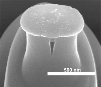
The “axial splitting” mode previously reportedReference Östlund, Howie, Ghisleni, Korte, Leifer, Clegg and Michler4, Reference Östlund, Rzepiejewska-Malyska, Leifer, Hale, Tang, Ballarini, Gerberich and Michler5, Reference Gerberich, Michler, Mook, Ghisleni, Östlund, Stauffer and Ballarini22 was observed in many of the compression experiments here (Fig. 1). Pillars of silicon, spinel, and indium arsenide oriented for duplex slip normally showed axial splitting above a critical diameter with a brittle-to-ductile transition below this diameter. Pillars of magnesium oxide were not observed to split by this mechanism at the diameter of 2 μm studied.
Si pillar of original top diameter 320 nm, after compression, showing an axial splitting crack.

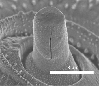
Some of the pillars studied slipped on only one plane, meaning that there was no intersection and no split nucleated. Several of these pillars were observed to crack in a hitherto unseen manner, where a crack grew in the upper portion of the pillar and from the side surface inward, termed “side splitting” here. This behavior was observed in indium arsenide micropillars (see Fig. 2).
InAs pillar of original top diameter 2 μm, after compression, showing a vertical crack in the slipped portion of the pillar. Beading on the surface of the pillar is an artifact from the focused ion beam milling process and is not thought to have any significant effect on the mechanical properties.

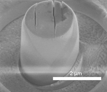
A number of compressed pillars showed arrays of cracks in the top surface, termed “top surface splitting” here. These cracks are typically parallel and oriented perpendicular to the horizontal projection of the slip direction. This type of behavior was observed in gallium arsenide and magnesium oxide micropillars (see Fig. 3).
MgO pillar of original top diameter 2 μm, after compression, showing an array of parallel cracks in the top surface.

Each of these fracture modes is discussed in more detail in the following.
A. Axial splitting
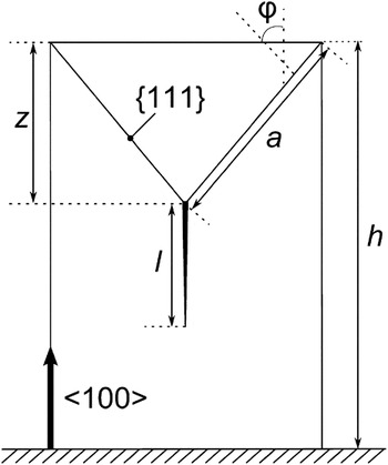
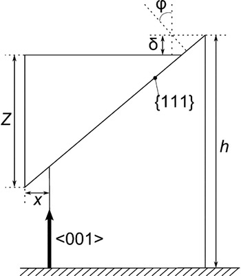
This model is described in detail elsewhereReference Östlund, Howie, Ghisleni, Korte, Leifer, Clegg and Michler4 and will only be summarized here. It was based on an analysis by Ashby and Sammis which considered the effect of compressive stress on a single defect at inclined angle to the loading axis.Reference Ashby and Sammis26 For simplicity, it was assumed that two opposing slip planes are activated and intersect, giving rise to dislocation pile-ups at a distance z below the top of the pillar causing a through-thickness axial splitting crack of length l (Fig. 4).
Geometry of the axial splitting mode. Schematic of a pillar having undergone slip on two intersecting systems, with definition of dimensions.

The stress intensity factor, K I, on the splitting crack of length l was estimated as
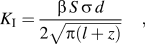
where β is some constant, S is the Schmid factor on the slip plane and in a direction from the top edge of the pillar to the line of intersection of the slip bands, as described in Östlund et al.,Reference Östlund, Howie, Ghisleni, Korte, Leifer, Clegg and Michler4σ is the stress applied to the top of the pillar, d is the pillar diameter, and z is the distance between the top of the pillar and the point where the slip planes intersect and scales with the pillar diameter. The stress intensity factor, K I,S, required to nucleate a split is found by setting l = 0. If it is assumed that the slip begins at the top edges of the pillar, an expression for z can be derived, giving the stress intensity factor, K I,S, required to nucleate the splitting crack

where k S is given by
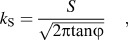
and φ is the angle between the slip plane normals and the compression axis.
The value of β was discussed briefly by Östlund et al.Reference Östlund, Howie, Ghisleni, Korte, Leifer, Clegg and Michler4 but will be treated in more detail here. It has two contributions: First, the analysis by Ashby and Sammis describes only one inclined plane.Reference Ashby and Sammis26 In the pillars studied here, two planes meet at the point of crack initiation; this doubles the energy release rate,Reference Lawn and Wilshaw27 introducing a factor of √2 into K I. Second, the model is essentially two-dimensional and treats the pillar as a cuboidal slab of material. In reality the pillars are cylindrical, and the slip planes that cut them elliptical rather than rectangular. This has the effect of reducing K I by the ratio of the area of an ellipse to that of the equivalent rectangle, i.e., π/4. These factors are collected together in the constant β, which has the value
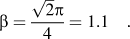
Crack growth can start when K I,S = K Ic, so that the applied compressive stress required to cause the split to grow from the intersection between the two slip bands is given by
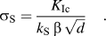
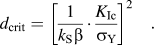
This stress increases as the pillar width is decreased. However, since slip is a prerequisite for crack nucleation, splitting can only occur when σ Y > σ S, and as σ S increases as the pillar diameter decreases, there is a minimum pillar width, d crit, below which K I,S < K Ic so that axial splitting cannot occur, given by
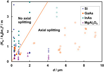
To account for the different material properties and slip geometries in the various materials, the experimental data has been plotted in the form (K Ic/k Sβσ Y)2 against d, using the data given in Table I and the value for β of 1.1 (Fig. 5). Samples where axial splitting was observed are plotted as open points on Fig. 5 and are filled if axial splitting was not observed. Data from Östlund et al.Reference Östlund, Howie, Ghisleni, Korte, Leifer, Clegg and Michler4, Reference Östlund, Rzepiejewska-Malyska, Leifer, Hale, Tang, Ballarini, Gerberich and Michler5 are included.
Experimental data, from this study and from Östlund et al.,Reference Östlund, Howie, Ghisleni, Korte, Leifer, Clegg and Michler4, Reference Östlund, Rzepiejewska-Malyska, Leifer, Hale, Tang, Ballarini, Gerberich and Michler5 plotted in the form (K Ic/k Sβσ Y)2 against d. Open symbols represent pillars that split axially; closed symbols represent pillars that deformed without axial splitting. The solid line is the transition defined by Eq. (6). Note that only axial splitting has been considered here; other cracks may be present in either regime.

Material properties and constants used in calculations.

Slip planes are those consistent with angles measured on deformed pillars; crack planes are then calculated according to the intersection between slip planes. φ is the angle between the slip plane normal and the compression axis, S is the Schmid factor as described in Östlund et al.,Reference Östlund, Howie, Ghisleni, Korte, Leifer, Clegg and Michler4 and k S is defined in Eq. (3).
The predicted boundary between regimes where through-thickness axial splitting can and cannot occur is a straight line of unit gradient, passing through the origin. Overall, a good agreement between the onset of splitting and the predictions of Eq. (6) is found, although a number of pillars (two of gallium arsenide and six of spinel) lie above the critical diameter for splitting but were not observed to crack. Furthermore, the absence of splitting in the magnesium oxide pillars is also consistent with these ideas as the ratio K Ic/σ Y is so much larger than in the other materials. A number of silicon pillars fall outside the predicted splitting regime but were observed to split. Note that the yield stresses and diameters plotted for these pillars are taken directly from Ref. Reference Östlund, Rzepiejewska-Malyska, Leifer, Hale, Tang, Ballarini, Gerberich and Michler5. The diameters quoted and used to calculate the yield stresses in Ref. Reference Östlund, Rzepiejewska-Malyska, Leifer, Hale, Tang, Ballarini, Gerberich and Michler5 were those at the mid-height of the pillar; the smaller diameters at the top of the pillar—where plastic flow occurs—give a yield stress higher than that reported and hence a smaller value of (K Ic/k Sβσ Y)2.
1. Effect of taper on the micropillar
None of the micropillars of interest here had perfectly straight sides; all had some taper. For pillars with a diameter of a few microns this was typically about 2°, but increased with decreasing pillar size to about 4° for the 300 nm pillars.Reference Östlund, Rzepiejewska-Malyska, Leifer, Hale, Tang, Ballarini, Gerberich and Michler5 The effect of the taper is to cause each ligament on either side of the crack to be loaded asymmetrically, so that it bends as described by Kendall.Reference Kendall19 This allows the compressive force to do work as the crack grows, giving rise to a crack driving force. Following Kendall and using strain energy release rates, rather than stress intensity factors, it is shown in Appendix A that the ratio of the crack driving force associated with the taper, G taper, as a fraction of the driving force for uniaxial splitting, G split, is given by

where α is the taper, c is the crack length and d is the diameter of the pillar at the crack tip. Substituting in the values of β = 1.1, S = 0.47 and φ = 54.7° for silicon gives
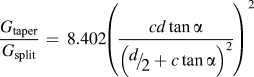
Taking c = z ≈ 0.7 d at the onset of splitting gives 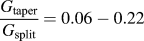 for α between 2 and 4°. The additional driving force due to the taper is therefore considered to be a secondary effect, at least where crack nucleation is concerned.
2. Extent of cracking
So far only the conditions for the onset of axial splitting have been considered. If loading is continued, it is expected that the crack would be further opened by the wedge formed by the intersecting slip bands.Reference Östlund, Rzepiejewska-Malyska, Leifer, Hale, Tang, Ballarini, Gerberich and Michler5 For a wedge of constant thickness 2b, the equilibrium crack length ahead of the wedge 7 is given byReference Lawn and Wilshaw27
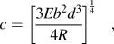
where R is the fracture energy.
If it is assumed that the wedge thickness scales linearly with the pillar size, then the equilibrium crack length should vary with pillar size according to c ∝ d 5/4. However, it has been foundReference Östlund, Rzepiejewska-Malyska, Leifer, Hale, Tang, Ballarini, Gerberich and Michler5 that increasing the diameter of silicon micropillars from 400 to 940 nm increases the measured crack length from 250 to 1250 nm, much greater than predicted by the above argument. It has, therefore, been suggested that there is an increase in the fracture toughness with decreasing pillar size and that this increase is associated with the observed brittle-to-ductile transition.
For axial splitting, cracking cannot start until a crack is nucleated by glide, so that for d > d crit, σ Y > σ S. The onset of cracking is, therefore, predicted to be followed by a burst of cracking to the stable crack length l*. Rearranging Eq. (1) gives
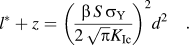
That is, (l* + z) ∝ d 2. Using the values for the pillars above gives the ratio of the two pillar diameters squared as 5.5, and the ratio of the final crack lengths seen by Östlund et al.Reference Östlund, Rzepiejewska-Malyska, Leifer, Hale, Tang, Ballarini, Gerberich and Michler5 is 5, consistent with the idea that the difference in crack lengths is caused by the burst of cracking that occurs immediately after the onset of cracking. Unfortunately, the axial splitting analysis predicted that pillars of this diameter and yield stress would not crack, so that estimates of the values of l* + z are less than the values of z predicted from the intersection of the two slip planes.
However, as mentioned previously, the diameters given for these pillars are those at mid-point of the pillar, but, as here, flow was observed to occur at the top of the pillar. Direct measurement of the larger pillar from the image given before testing by Fig. 2(b) of Ref. Reference Östlund, Rzepiejewska-Malyska, Leifer, Hale, Tang, Ballarini, Gerberich and Michler5, yields a diameter of the top of approximately 620 nm, consistent with the aspect ratio of 4 and pillar height given. The load at which a first deviation from linear loading can be seen in the same reference, Fig. 2(b) of Östlund et al.,Reference Östlund, Rzepiejewska-Malyska, Leifer, Hale, Tang, Ballarini, Gerberich and Michler5 is approximately 3.1 mN, so that the yield stress, based on this load and the top diameter measured is 10.3 GPa. A similar estimate for the smaller (400 nm) pillar is more difficult as there is no image prior to deformation, but assuming the same ratio between middle and top diameter, the latter might be estimated as 264 nm. The load at yield, determined as before, Fig. 2(c) of Ref. Reference Östlund, Rzepiejewska-Malyska, Leifer, Hale, Tang, Ballarini, Gerberich and Michler5, is approximately 0.57 mN, which gives a yield stress of 10.4 GPa. The constant level of these yield stresses is consistent with those calculated by Fig. 1 of Ref. Reference Östlund, Rzepiejewska-Malyska, Leifer, Hale, Tang, Ballarini, Gerberich and Michler5 for the middle diameters and supports the assumption of a similar taper in both pillars.
Substituting these values for d and σ Y into Eq. (10) gives predicted crack lengths of 1070 and 198 nm, somewhat less than the values observed. Subsequent loading would increase the crack length, but the displacements beyond the initial burst in the load–displacement curvesReference Östlund, Rzepiejewska-Malyska, Leifer, Hale, Tang, Ballarini, Gerberich and Michler5 are only of the order of 30 nm, indicating that there is relatively little subsequent cracking.
The good agreement between this simple estimate and the observed crack lengths is certainly partly fortuitous. The main uncertainty associated with this estimate is the measurement of the pillar diameter. Inclusion of an error in measurement of the top diameter of 10% results in predicted crack lengths before additional loading of 880–1314 nm for the large pillar and 164–245 nm for the smaller pillar. A more detailed analysis should also include the effect of changing diameter and stress level along the pillar axis during propagation of the crack, which would lead to a reduction in final crack length, although the relative lengths of cracks in pillars of different diameters would remain approximately the same for pillars with similar taper.
B. Side splitting of slipped material
Some of the indium arsenide pillars slipped predominantly on one plane, so that there were no pronounced intersections of glide planes and no axial splitting was observed. However, in several of these pillars, a vertical crack was observed to grow in the part of the pillar above the glide plane and inward from the side surface (see Fig. 2).
Compression of the pillar along its axis causes Poisson expansion in perpendicular directions. As the pillar slips in a single direction, the outer layer of material overhangs the base of the pillar, so that the axial load in the overhanging material is relaxed and with it, the original Poisson expansion. However, this layer is constrained by the underlying material, so that it is thrown into tension.
To see if a sufficient driving force might exist to cause cracking, consider a pillar that has slipped on just one plane (Fig. 6). If the square pillar, of side length d, is compressed axially through a distance, δ, slip gives rise to an overhang of maximum height Z and width x, given by

Geometry of the side splitting mode. Schematic of a pillar having undergone slip on a single system, with definition of dimensions. The extent of plastic deformation has been exaggerated.

where φ is the angle between the slip plan normal and the compression axis. The axial strain, ε, and transverse strain, ε t, in the pillar are then

where ν is Poisson’s ratio.
Assuming that the width of the overhanging layer is small, the elastic strain energy stored in the free layer is
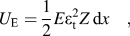
where Z dx is the volume of material.
If a crack is allowed to grow by dc from the free surface toward the bulk of the pillar, the elastic energy change is

The factor (1 − c/x) arises because of the constraint applied to the remainder of the pillar; at the edge of the free layer, i.e., where c = x, no elastic energy can be released, and it is assumed to vary linearly between here and the free surface, as in a constrained film on a substrate.Reference Beuth37
The increase in surface energy, dU S, is given by

where R is the fracture energy.
This leads to an equilibrium crack length
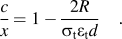
Substituting in expressions for σ t and ε t from above we obtain

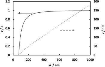
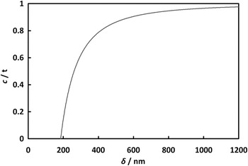
This relationship, along with the absolute crack length, c, is plotted on Fig. 7 for an indium arsenide pillar with d = 2 μm, h = 5 μm, and the material properties taken from Table I.
Equilibrium length of a side crack in an InAs pillar with d = 2 μm, h = 5 μm, in terms of the lateral displacement, x, (solid line, left axis) and as an absolute length (dashed line, right axis).

It can be seen that a compressive displacement of approximately 70 nm is required before cracking is energetically favorable, but that after a few hundred nanometers of displacement, virtually the whole depth of the overhanging layer is cracked. The displacement in this sample was measured to be approximately 500 nm from the load–displacement curve. It can be seen in Fig. 2 that the crack has indeed not penetrated beyond the overhanging layer into the body of the pillar.
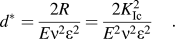
The conditions required to nucleate a crack may be investigated by setting c = 0 in Eq. (17). This leads to a relationship between strain and pillar diameter and thence to size-dependent cracking and a threshold diameter given by
Alternatively, for a pillar of a given diameter, the threshold value of strain, ε*, required before cracking starts is given by
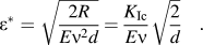
Using the material properties in Table I, the values of ε* for a 1 μm pillar vary from approximately 2% for the compound semiconductors and spinel to about 7% for magnesium oxide. This is consistent with the observations of side splitting in indium arsenide but not in magnesium oxide. That this form of cracking does not occur in spinel is consistent with the observation that plastic flow takes place over wide bands rather than single planes as assumed in the analysis, so that the overhang, x, of any one plane is not as large as that given in Fig. 6, decreasing the driving force for cracking.
C. Top surface splitting
A number of compressed pillars showed arrays of cracks in the top surface. Examples of this type of behavior were seen in gallium arsenide and magnesium oxide (Fig. 3). The cracks were parallel to one another and oriented perpendicular to the projection of the slip direction, suggesting that these are directly associated with the change in shape of the sample, rather than, for example, hard particles trapped between the pillar and the punch.
It is normally observed that the top of the pillar is circular, whereas the pillar body has a more oval cross-section caused by duplex slip on intersecting slip planes. This presumably arises from constraint of the top surface due to the friction between the pillar and the punch. As the material in the pillar as a whole deforms, a tensile strain is imposed on the constrained surface which can be relaxed when the punch is removed, giving rise to the observed cracking.
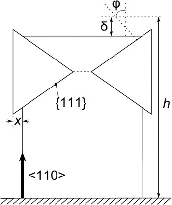
When duplex slip occurs, the sideways displacement, see Fig. 8, is given by

Geometry of the top surface splitting mode. Schematic of a pillar having undergone duplex slip, with definition of dimensions. The extent of plastic deformation has been exaggerated.

This represents an increase in the size of the bulk of the pillar relative to a constrained top layer. When the punch is removed, the top layer will strain to conform to the rest of the pillar.
The transverse strain in the top surface of the pillar is given by approximately

The elastic strain energy stored in the constrained top layer is
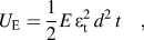
where t is the thickness of this layer and d 2t is the volume of material, assuming again a square pillar cross-section. If a crack is allowed to grow from the top surface down into the pillar, this energy will be released. The elastic energy change as this crack is extended a distance dc is

The factor (1 − c/t) arises because of the constraint applied by the remainder of the pillar; at the boundary between constrained top layer and the rest of the pillar, i.e., where c = t, no elastic energy can be released and it is assumed to vary linearly between here and the free surface.
The surface energy term is

which leads to an equilibrium crack length given by
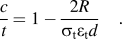
Substituting in expressions for σ t and ε t from above we obtain
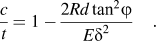
This relationship is plotted on Fig. 9 for a <110>-oriented magnesium oxide pillar with d = 2 μm and h = 5 μm.
Equilibrium crack length as a function of maximum displacement z for an MgO pillar with d = 2 μm, h = 5 μm.

The pillars studied here have approximately the same aspect ratio, ξ, so that the longitudinal strain, ε, can be expressed as
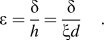
Using this to substitute for δ in Eq. (26) gives
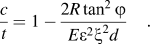
The depth of the crack is, therefore, predicted to again increase with pillar size.
The critical diameter, d*, below which cracking will not occur can be found by setting c = 0.

Alternatively, for a given pillar diameter, there is a minimum plastic strain required for cracking to occur.
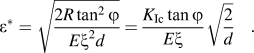
Perhaps the most important feature of this form of cracking is that the cracks should not be able to propagate further than the thickness of the constrained surface layer. This is consistent with the observation that the maximum depth of such cracks is limited to a few tens of nanometers.
Using the material properties in Table I the predicted threshold strains for a 1 μm pillar vary from 0.3% in spinel to 0.8% in magnesium oxide. These strains are small compared with the strains imposed on most pillars. The explanation above assumes that the top surface of the pillar is fully constrained, presumably by friction, when pressed against the diamond punch. This may not be the case particularly in silicon, where the coefficient of friction between the diamond punch and the pillar is relatively low: 0.05,Reference Çağin, Che, Gardos, Fijany and Goddard38 compared with 0.17 for magnesium oxide.Reference Bowden and Brookes39 Such cracking would also require that the underlying material be as stiff as possible, so that the driving force could be reduced by the presence of axial splitting that would increase the compliance of the pillar as a whole. The magnitude of this effect is not understood at present and requires further analysis.
IV. OCCURRENCE OF DIFFERENT FRACTURE MODES
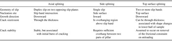
The basic features of each of the three mechanisms described here are summarized in Table II. These are the mechanisms that were observed in the single crystals tested. It is not intended to be a complete list of possible fracture processes; in polycrystals for instance, one might envisage failure occurring by some sort of grain boundary failure. The final step here is to see under what conditions the different fracture modes are preferred and whether one might map out different regimes of fracture behavior. Expressions for the crack driving forces have been obtained for all three of the failure mechanisms observed, giving the conditions under which each is energetically favorable. Each of these analyses assumes that plastic deformation occurs in a particular way. For instance, axial splitting requires intersecting slip bands, whereas the driving force for side splitting depends on the magnitude of the overhang.
Summary of the main characteristics of the different cracking modes.

Furthermore, the different modes occur in different parts of the pillar. Axial splitting below the initial slip bands, side splitting above the slip bands, but in the overhanging side, and top surface cracking in the top surface, above the intact region of the pillar. It is suggested that top surface cracks occur on unloading. One uncertainty is whether the driving force for top surface splitting is modified by changes in the pillar compliance, for instance, due to axial splitting. Other than this, it is believed that the different modes of cracking observed operate relatively independently and that the observed mechanism is determined primarily by the nature of plastic deformation in the pillar. Distinct regimes in which different modes of cracking operate are therefore difficult to define.
However, experiments show that the most damaging form of cracking is axial splitting, which can lead to complete fragmentation of the pillar. It is, therefore, this form of cracking which should be used to determine the onset of the brittle-to-ductile transition that has been observed with decreasing size.
V. CONCLUSIONS
Cracking was studied in single-crystal micropillars of silicon, indium arsenide, magnesium oxide, and magnesium aluminate spinel and compared with existing observations in silicon and gallium arsenide micropillars. The most common mode of failure was through-thickness axial splitting with the split being nucleated at intersecting slip bands. Provided intersecting slip bands were formed, this was observed in all pillars above a critical size. This critical size is consistent with the predictions of an analysis in all of the materials tested, despite the differences in material properties and slip crystallography. It has also been shown that as intersecting slip bands can only be formed once the pillar has started to yield, the yield stress of the pillar will be greater than that required for splitting above the critical size. This leads to a burst of crack growth, whose magnitude is consistent with observations elsewhere.Reference Östlund, Rzepiejewska-Malyska, Leifer, Hale, Tang, Ballarini, Gerberich and Michler5
Cracking can also occur by cracking in the side and in the top surface of the pillar. Both occur in the portion of the pillar above the glide bands. The former has been associated with the Poisson relaxation that occurs when an overhanging region of material is formed above a glide band. The latter has been attributed to the surface of the pillar being under a frictional constraint, as the pillar underneath deforms, and the surface being thrown into tension as the sample is unloaded. Both ideas are consistent with the observed mode of cracking and with the observations that such a cracking is relatively limited and gives magnitudes of cracking consistent with what is observed, and expressions for the crack driving forces for these mechanisms have been derived. Unlike these two mechanisms, through-thickness axial splitting can lead to complete failure of the pillar at relatively low strains. It is, therefore, suggested that this form of cracking is most important in determining the brittle-to-ductile transition that has been observed and that this arises due to a reduction in the stress intensity factor with decreasing pillar size.
ACKNOWLEDGMENTS
The authors acknowledge J. Michler, R. Ghisleni, and W. W. Gerberich for helpful discussions. This work was supported by the Engineering and Physical Sciences Research Council [EP/F033605/1] (PRH) and [EP/C518012/1] (SK).
APPENDIX A
Kendall describes, in terms of global energy changes, the formation of splitting cracks in columns compressed using a punch with a width smaller than that of the column itself.Reference Kendall19 Each half-column is then loaded asymmetrically and bends, allowing the compressive force to move downward and do work. In the absence of frictional effects, this driving force goes to zero as the punch width approaches the pillar width. In micropillar compression, where the punch is typically much larger than the pillar top, one might expect no effect. However, an effect arises because the pillar tapers, so that the centroid of each half pillar is closer to the axis at the top of the pillar than it is at the bottom. Kendall’s calculation has been adapted to estimate the magnitude of this effect on the driving force due to through-thickness axial splitting.
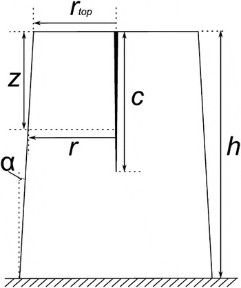
Consider the pillar shown in Fig. A1, the centroid of each semicylindrical slice is at a distance y′ from the center of the pillar, where

Schematic of a tapered pillar containing an axial split, with definition of dimensions used in this appendix.

r is the radius of the pillar at some depth in the pillar and depends on the vertical position within the pillar and on the taper angle, α

where r top is the radius of the top of the pillar and z is the distance from the top of the pillar. The second moment of area with respect to the centroid axis is

The bending moment in each slice through the pillar is produced by the difference in centroid position

where

The bending strain energy in the two beams taken together is given by
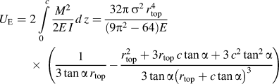
so that the contribution to the driving force from the taper is
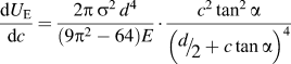
where d is taken to be equal to 2r top. Expressing the stress intensity factor of the crack derived for uniaxial splitting, Equation (2), in terms of a crack driving force gives

The relative value of the two driving forces is therefore given by

Taking typical values for silicon micropillars of β = 1.1, S = 0.47 and φ = 54.7° and taking c = z ≈ 0.7 d at the onset of splitting gives 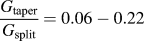 for α between 2 and 4°. The additional driving force due to the taper is therefore considered to be a secondary effect, at least where crack nucleation is concerned.