

Implications
Porcine coronary procedures are widely performed worldwide to investigate novel cardiovascular therapies. The acceptable mortality rate in the literature for these procedures is far higher than that for humans; some of these deaths are almost certainly related to poor technique, and therefore avoidable. Despite this, no detailed description of the procedure has been published to guide investigators performing this procedure. We hope that by providing a systematic review of the technique the safety of pig coronary procedures can be improved and animal mortality minimised.
Introduction
Assessment of safety and efficacy within the porcine coronary artery model remains a standard requirement for new therapies intended for delivery to the coronary arteries before proceeding to clinical testing. Although the model is well established for new stent-based technologies, novel gene and stem cell therapies are increasingly being investigated.
Some aspects of the procedure are similar to human coronary angiography and percutaneous coronary intervention (PCI). However, there are important differences between the two species in terms of responses to anaesthesia, pharmacotherapy, vascular access, catheter selection and angiographic views. Although guidelines exist (Schwartz et al., Reference Schwartz, Edelman, Carter, Chronos, Rogers, Robinson, Waksman, Weinberger, Wilensky, Jensen, Zuckerman and Virmani2002; Lowe et al., Reference Lowe, Schwartz, Mac Neill, Jang, Hayase, Rogers and Oesterle2003), there is no systematic description of the procedure in the literature, and most published reports only briefly summarise the methodology, thus providing insufficient detail for a researcher wishing to set up this model de novo, even if they have experience in human catheter-based coronary procedures.
There is an international consensus on best practice for human PCI, and the mortality associated with the procedure has steadily fallen as techniques have evolved, with current rates substantially less than 1% (Hannan et al., Reference Hannan, Racz, Holmes, Walford, Sharma, Katz, Jones and King2008). However, the methodology in published reports of the porcine coronary model varies markedly, and early mortality rates as high as 15% have been considered acceptable, despite these animals being healthy and without overt coronary disease (Schwartz et al., Reference Schwartz, Edelman, Carter, Chronos, Rogers, Robinson, Waksman, Weinberger, Wilensky, Jensen, Zuckerman and Virmani2002). Although some of these deaths may relate to the experimental nature of new technologies, it is likely that a large proportion are related to poor technique or inexperienced operators.
This review will discuss the procedure of porcine coronary angiography and stent implantation as performed in our institution (Appleby et al., Reference Appleby, Kingston, David, Gerdes, Umana, Castro, Lowenstein and Heagerty2003; Kingston et al., Reference Kingston, Sinha, Appleby, David, Verakis, Castro, Lowenstein and Heagerty2003; Salem et al., Reference Salem, Ranjzad, Driessen, Appleby, Heagerty and Kingston2006). The similarities and differences with the human procedure are highlighted, and the variations in the technique that have been described are included. The level of detail should be sufficient for researchers who are not already experienced at coronary procedures. Although other forms of experimental coronary intervention are beyond the scope of this article, the steps leading up to guide catheter placement are still pertinent. If the procedure is performed correctly, the early mortality should be very low and is less than 1% in our institution with the technique as described.
General considerations
The porcine model of instent restenosis was first described in 1990, with the reliable development of neointima at 28 days following stent implantation in undiseased coronary arteries (Schwartz et al., Reference Schwartz, Murphy, Edwards, Camrud, Vliestra and Holmes1990). Current guidelines recommend the juvenile normocholesterolaemic domestic cross-bred farm pig or adult miniature pig as the porcine models of choice for studies of new stent technologies (Schwartz et al., Reference Schwartz, Edelman, Carter, Chronos, Rogers, Robinson, Waksman, Weinberger, Wilensky, Jensen, Zuckerman and Virmani2002). Although swine with familial and diet-induced hypercholesterolaemia do develop advanced atherosclerosis, this model is impractical for most pre-clinical studies as the process can take several years by which time the pigs often weigh in excess of 200 kg (Granada et al., Reference Granada, Kaluza, Wilensky, Biedermann, Schwartz and Falk2009). Injury models are interesting and may result in atherosclerotic lesions that resemble those in humans, with a necrotic core and thin fibrous cap (Thim et al., Reference Thim, Hagensen, Drouet, Bal Dit Sollier, Bonneau, Granada, Nielsen, Paaske, Botker and Falk2010). However, there is significant biological variability within these models, and it is unclear how closely they mirror chronic atherosclerosis in humans. Porcine models of atherosclerosis have recently been reviewed and will not be discussed further in this article (Granada et al., Reference Granada, Kaluza, Wilensky, Biedermann, Schwartz and Falk2009).
For pigs weighing approximately 30 to 50 kg, the heart and coronary arteries are approximately the same size as in the adult human. In our institution, we use juvenile Large White pigs that are between 8 and 12 weeks old and weigh between 18 and 25 kg.
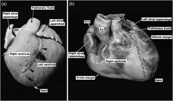
Pig and human hearts are very similar structurally, although minor differences exist (Figure 1; Crick et al., Reference Crick, Sheppard, Ho, Gebstein and Anderson1998). Porcine coronary artery anatomy and distribution is also analogous to that in humans (Weaver et al., Reference Weaver, Pantely, Bristow and Ladley1986). The left coronary artery (LCA) arises from the left coronary cusp and bifurcates shortly after its origin into the left anterior descending coronary artery (LAD), which runs anteriorly in the interventricular groove, and circumflex artery (Cx), which runs laterally and posteriorly in the atrioventricular groove. As in humans, the left main stem (LMS) of the LCA is of variable length and uncommonly may be non-existent with separate origins of the LAD and Cx from the left coronary cusp. The right coronary artery (RCA) arises from the right coronary cusp and is dominant in about 80% of cases (Weaver et al., Reference Weaver, Pantely, Bristow and Ladley1986), supplying the posterior descending coronary artery in the posterior interventricular groove. Unlike other mammalian models investigated, but similar to humans, there is minimal pre-existing coronary collateral flow (Maxwell et al., Reference Maxwell, Hearse and Yellon1987; White et al., Reference White, Carroll, Magnet and Bloor1992).
Differences in the orientation of pig and human hearts. Pig (a) and human (b) hearts in the anteroposterior plane. Arrowheads indicate the interventricular groove in which the left anterior descending coronary artery runs. AO = aorta; SCV = superior caval vein.

Despite the similarities between the two species, there are differences in the location and orientation of the heart within the thoracic cavity. The pig thorax is more oval in the anteroposterior (AP) direction than the human cavity, which is more oval laterally. The morphological apex of the porcine heart lies retrosternally in the midline and is composed almost entirely of left ventricular tissue. This contrasts with the human heart wherein the apex lies on the left side of the thoracic cavity, and consists of both right and left ventricular tissue as the interventricular groove extends to the apex (Figure 1; Crick et al., Reference Crick, Sheppard, Ho, Gebstein and Anderson1998). As a result of these differences, in the AP plane the LAD runs to the left in humans, whereas it runs to the right (and does not reach the apex) in pigs. Thus, the angiographic views are not directly comparable, and this will be discussed in more detail later on in this article.
Procedural technique
Operating theatre requirements
The procedure is performed in an operating theatre under sterile conditions. A mobile or fixed image intensifier with a C-arm is required for fluoroscopy, and an anaesthetic machine, electrocardiogram (ECG) monitoring and pulse oximetry should be available. Most of the other equipment required for the procedure is identical to that used in human coronary procedures.
Periprocedural pharmacotherapy
Humans undergoing PCI are routinely prescribed oral dual antiplatelet therapy, usually in the form of aspirin and the thienopyridine clopidogrel. This combination has also been recommended by a consensus group for use in pre-clinical animal studies of new stent technologies in order to prevent the catastrophic, and often fatal, complication of stent thrombosis (Schwartz et al., Reference Schwartz, Edelman, Carter, Chronos, Rogers, Robinson, Waksman, Weinberger, Wilensky, Jensen, Zuckerman and Virmani2002).
Given the lack of experimental animal data, antiplatelet agent dosing is to some extent empirical, and guidelines suggest that doses should be at the operator's discretion (Schwartz et al., Reference Schwartz, Edelman, Carter, Chronos, Rogers, Robinson, Waksman, Weinberger, Wilensky, Jensen, Zuckerman and Virmani2002). The majority of published studies have used total loading doses of aspirin and clopidogrel of approximately 300 mg, followed by maintenance daily doses of 75 to 100 mg of aspirin and 75 mg of clopidogrel (Seifert et al., Reference Seifert, Huibregtse, Polovick and Poff2007; Chung et al., Reference Chung, Kim, Pak, Jang, Yang, Han, Park, Park, Huh, Wight and Ueno2010; Posa et al., Reference Posa, Nyolczas, Hemetsberger, Pavo, Petnehazy, Petrasi, Sangiorgi and Gyongyosi2010; Tellez et al., Reference Tellez, Krueger, Seifert, Winsor-Hines, Piedrahita, Cheng, Milewski, Aboodi, Yi, McGregor, Crenshaw, Reed, Huibregtse, Kaluza and Granada2010). We use similar dosing schedules to those in humans undergoing stent deployment and load with 150 mg of aspirin and 150 mg of clopidogrel on both the day before and the day of the procedure, and then give 75 mg of each agent on a daily basis until the time of sacrifice. The tablets are crushed and mixed in with the chow of the animals. Although the maintenance dose is somewhat higher than that typically used in humans on a weight basis, the bleeding risk is very low in young healthy animals, and stent thrombosis represents a very serious potential complication. Cheaper generic formulations of clopidogrel have recently become available, which we have been using with no apparent increase in complications.
For interventional procedures, heparin is given once arterial access has been gained so as to reduce the risk of wire and stent thrombosis (Lowe et al., Reference Lowe, Schwartz, Mac Neill, Jang, Hayase, Rogers and Oesterle2003). Although some authors have used doses as high as 10 000 U (Frimerman et al., Reference Frimerman, Welch, Jin, Eigler, Yei, Forrester, Honda, Makkar, Barber and Litvack1999), we and others (Gunn et al., Reference Gunn, Arnold, Chan, Shepherd, Cumberland and Crossman2002), use a standard heparin dose of 2500 U for juvenile animals (which is approximately 100 U/kg) and have had no issues with acute stent thrombosis. In humans, heparin is not usually given if angiography alone is planned without coronary intervention, and we extend this practice to the porcine model.
In our institution, we do not administer antibiotics or antiarrhythmic drugs routinely. Some operators recommend routine antibiotics; however, there is no evidence for this practice and infection is rare if meticulous sterile procedure is followed. The antiarrhythmic drug bretylium (5 mg/kg) used to be commonly given prophylactically. However, this is not standard practice for human procedures; all antiarrhythmic agents have the potential to be proarrhythmic, and rhythm disturbances are rare if the procedure is performed carefully. An important observation is that in cases of ventricular arrhythmia in pigs, external direct current cardioversion is rarely successful because of the high impedance from the thick muscle overlying the thorax. Pharmacological cardioversion with antiarrhythmic agents such as amiodarone and lidocaine can be attempted, but in our experience it is rarely successful. As ventricular arrythmias most commonly arise because of inadvertent injection of air into the coronary arteries or prolonged coronary occlusion, this complication can be avoided in most cases with careful technique.
Intracoronary glyceryl trinitrate (GTN) can be administered to achieve maximal coronary dilatation before performing quantitative coronary angiography or to relieve coronary spasm induced by the catheter or stent deployment. It is typically given as a bolus dose of 100 to 200 μg directly into the coronary artery via a catheter.
Anaesthesia
Although human procedures are almost always performed under local anaesthesia, this is clearly not an option for animals in which general anaesthesia is required. Endotracheal intubation is highly recommended as deaths have occurred when the animal is left to breathe spontaneously with anaesthesia administered by a mask, and ventricular arrhythmias are more likely under such circumstances in our experience. ECG and pulse oximetry monitoring are routinely performed. Anaesthesia in swine has been reviewed recently (Smith and Swindle, Reference Smith and Swindle2008), and the reader is directed to this article for detailed information on this subject.
The method of induction will depend on local veterinary practice. Methods include varying doses and combinations of intramuscular agents (for instance, azaperone 12 mg/kg (Gunn et al., Reference Gunn, Arnold, Chan, Shepherd, Cumberland and Crossman2002), xylazine 1 to 2.2 mg/kg (Frimerman et al., Reference Frimerman, Welch, Jin, Eigler, Yei, Forrester, Honda, Makkar, Barber and Litvack1999), ketamine 10 to 20 mg/kg and acetylpromazine 0.22 mg/kg (Heldman et al., Reference Heldman, Cheng, Jenkins, Heller, Kim, Ware, Nater, Hruban, Rezai, Abella, Bunge, Kinsella, Sollott, Lakatta, Brinker, Hunter and Froehlich2001) and telazolol 6.6 mg/kg (Long et al., Reference Long, Bratz, Alloosh, Edwards and Sturek2010)) or gas induction (Appleby et al., Reference Appleby, Kingston, David, Gerdes, Umana, Castro, Lowenstein and Heagerty2003; Salem et al., Reference Salem, Ranjzad, Driessen, Appleby, Heagerty and Kingston2006). In our institution, we use gas induction with 4% isoflurane in oxygen (5 l/min) and nitrous oxide (2 l/min). Atropine (0.05 mg/kg) is sometimes given to reduce salivary flow; however, we do not find this agent particularly useful.
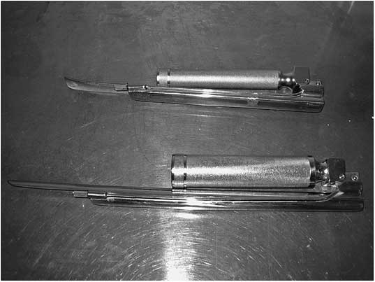
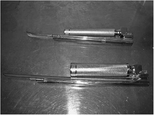
Pigs can be intubated either while supine or prone. A long straight-bladed Magill laryngoscope is generally required because of the length of the oral cavity and the pharynx (Figure 2). An assistant is required to hold open the pig's mouth. If the pig is supine, the assistant also needs to lift and apply traction to the tongue. If prone intubation is performed, a sling can be used to lift the pig's upper jaw, while the tongue is depressed with the laryngoscope.
Straight-bladed Magill laryngoscopes.
Once the vocal cords are visualised, local anaesthetic spray (lidocaine) is administered to reduce laryngospasm and the pig is re-oxygenated for 1 to 2 min. Standard lubricated human endotracheal tubes are suitable for intubation and are best placed with the insertion of a bougie to stiffen the tube. Usually, 6 French tubes will be suitable; however, 7.5 or 8.0 French tubes may be required for larger animals.
Gas maintenance of anaesthesia is routine. Isoflurane is currently considered the inhalational agent of choice in swine (Smith and Swindle, Reference Smith and Swindle2008), and we use isoflurane, 3% in oxygen, in our institution. Sevoflurane is an alternative agent that may offer some safety advantages, but is more expensive. Older agents such as halothane and enflurane are no longer recommended because of their side-effect profiles. Halothane in particular is no longer used as it may induce malignant hyperthermia. This genetic condition, also known as Porcine Stress Syndrome, is not uncommon in pigs as a result of inbreeding and is invariably fatal. Using the above anaesthetic regimens, the pig will usually spontaneously breathe throughout the procedure, and mechanical ventilation is infrequently required. This substantially reduces the post-operative recovery time.
Arterial access
In humans, the femoral and radial arteries are the most common routes of arterial access for coronary procedures. In pigs, the carotid artery is most often used, although the femoral artery approach has also been described (Edelman et al., Reference Edelman, Seifert, Groothuis, Morss, Bornstein and Rogers2001; Long et al., Reference Long, Bratz, Alloosh, Edwards and Sturek2010). The main blood supply to the brain in ungulates is from the carotid arteries and, unlike in man, there is minimal contribution from the vertebral system. However, porcine vertebral arteries are more developed than in ruminants, and the circle of Willis is well developed with minimal variation. This is distinct from the situation in humans, in which incomplete circles are common (Ashwini, Reference Ashwini, Shuba and Jayanthi2008). As a result, unilateral carotid artery ligation in the pig does not result in neurological sequalae.
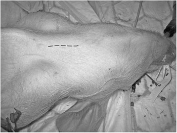
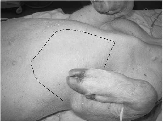
The following is a description of the left common carotid approach. The carotid pulse is not always externally palpable in the pig because of the thickness of the skin and subcutaneous tissues. Following cleansing of the skin, a sterile field is obtained with drapes. An approximately 8-cm long paratracheal incision is made bisecting a line between the manubrium and the angle of the jaw (Figure 3). A midline incision over the trachea offers an alternative approach. Blunt dissection through the subcutaneous tissues and platysma muscle is performed, at which point the carotid artery can be located by palpation. In the juvenile pig, the thymus gland lies adjacent to the neurovascular bundle and can obscure the view. The carotid artery lies in a neurovascular bundle along with the internal jugular vein and vagus nerve (Figure 4a). Inexperienced operators may inadvertently attempt to cannulate one of these two structures. The carotid artery is identifiable by its pulsatile nature, its size (being smaller than the jugular vein but larger than the vagus) and its colour (bright red as opposed to the darker red jugular vein and white vagus).
Left paratracheal incision for carotid artery access.

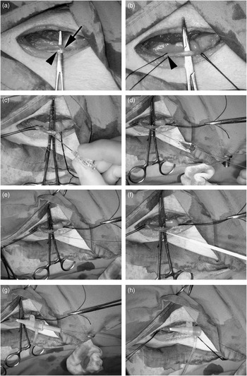
Sheath insertion into the left carotid artery using the modified Seldinger technique. Using blunt dissection, the carotid artery (a; arrow) is mobilised. The vagus nerve is in close proximity (arrowhead). The carotid artery is isolated (b), the distal vessel is ligated and a loose suture is placed around the proximal vessel (arrowhead). The introducer needle is inserted into the artery (c) and, when there is free flow of blood, a guidewire is passed, which should enter without resistance (d). The needle is withdrawn over the wire (e) and the sheath and dilator are threaded onto the wire (f) and into the artery (g). Finally, the dilator and wire are removed, leaving the sheath in place (h).

Once the carotid artery is freed from its surrounding fascia, two sutures are looped around the vessel. The cranial suture can be tied off at this point, if desired, and the caudal tie is secured in artery forceps so that haemostasis can be rapidly achieved if there is sheath dislodgement. An artery forceps placed under the carotid artery facilitates subsequent vascular access by immobilising the vessel. Arterial entry has historically been obtained via an arteriotomy; however, a modified Seldinger technique is quicker, safer and results in less bleeding. This technique is illustrated in Figure 4. We find that short sheaths designed for human radial access are preferable to femoral sheaths as they have a more tapered introducer tip and enter the vessel more smoothly. The sheath size depends on the interventional equipment being used, but most pig carotid arteries will comfortably accept sheaths up to 8 French in diameter (internal lumen diameter 2.66 mm).
If repeat angiography is required at the time of sacrifice, the contralateral carotid artery can be used.
The femoral artery can also be used as an access route via a surgical cut-down and sheath insertion using an arteriotomy or modified Seldinger technique (Long et al., Reference Long, Bratz, Alloosh, Edwards and Sturek2010) as described above. As with the carotid artery, femoral artery ligation appears to be well tolerated, and clinical complications are extremely rare.
Catheter selection
As a result of the anatomical differences, standard catheter shapes designed for human procedures (for instance, Judkins left and right, JL and JR, respectively) do not always reliably allow selective access to the porcine coronary arteries. Various catheters have been used to engage the porcine coronary ostia, with the choice dependent on which vascular access route has been utilised. Although diagnostic catheters can be used for angiography, stiffer guide catheters are required if intervention is to be performed.
For the carotid artery approach, Amplatz right (AR1) and left (AL1.75 or 2) and hockey stick catheters have been used to engage both coronary ostia (Frimerman et al., Reference Frimerman, Welch, Jin, Eigler, Yei, Forrester, Honda, Makkar, Barber and Litvack1999; Gunn et al., Reference Gunn, Arnold, Chan, Shepherd, Cumberland and Crossman2002; Russo et al., Reference Russo, Silva and Yeager2007). The JR4 catheter can also be used to engage both arteries (Heldman et al., Reference Heldman, Cheng, Jenkins, Heller, Kim, Ware, Nater, Hruban, Rezai, Abella, Bunge, Kinsella, Sollott, Lakatta, Brinker, Hunter and Froehlich2001) and is our first-line catheter, although it can paradoxically prove more difficult to engage the RCA than the LCA. Standard extra back-up and JL3.5 or JL4 catheters can also be useful for the LCA.
For the femoral approach, the AR1 or hockey stick catheters can be used to engage both coronaries and JL3.5 and AL0.75 to 2 can be used to engage the LCA.
Coronary angiographic projections
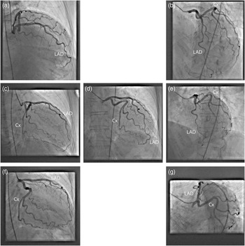
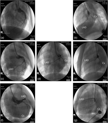
As discussed earlier, angiographic views in the pig differ from those in the human, as shown in Figures 5 and 6. In most cases, the AP and left anterior oblique (LAO) views are sufficient for delivery of stents to the proximal LAD and Cx and, in these views, the LAD lies to the left of the guide catheter tip and the Cx to the right (Figure 5d and e). If delivery to the ostia of the vessels is required, then a right anterior oblique (RAO) caudal view demonstrates the LMS bifurcation well and approximates the ‘spider’ LAO caudal view in humans.
Angiographic views of the human left coronary artery. Panels a–g show the same views as in Figure 5. All angulations are approximately 30°. Cx = circumflex artery; LAD = left anterior descending coronary artery.

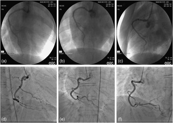
Imaging of the RCA is more straightforward than that of the LCA, and an AP view should provide satisfactory views, although the RAO and LAO are also useful (Figure 7).
Basic principles of coronary angiography
Coronary angiography following sheath insertion is similar to that in the human and will be discussed here only briefly for the interest of those unfamiliar with the technique. The reader is directed to one of the many excellent textbooks on human coronary procedures for more detail.
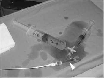
Briefly, the selected catheter is passed into the arterial sheath and connected to a Y connector with an O-ring valve (Figure 8, arrowhead), to allow introduction of equipment if intervention is planned, and a three-way tap. If arterial pressure transduction is available, a manifold can be connected to the three-way tap, which enables easy transition between contrast injection and pressure measurement. However, continuous arterial pressure measurement is not mandatory, as serious issues related to hypotension are exceptionally rare in healthy young animals. If a manifold system is not available, a simple injection system consisting of a 50 ml contrast reservoir syringe and a 10 ml luer lock injection syringe connected to the three-way tap can be used (Figure 8). This set-up reduces the number of syringe changes and minimises the possibility of air entry into the system compared with direct injection down the catheter.
Simplified injection system for coronary procedures. The arrowhead indicates a Y connector with an O-ring valve to facilitate entry of interventional equipment.

An important requirement of any coronary procedure is that air must not enter the catheter system as this can result in fatal ventricular arrhythmias. Before engagement of the coronary arteries, blood should be aspirated to ensure that there is no air trapped in the catheter. After each syringe change, the injection system must again be carefully re-examined to ensure no air has entered the system.
Following de-airing, the catheter is passed into the aortic root. Although in humans, catheters are advanced over a 0.035″ guidewire, this is not necessary when carotid access is used, as the catheter only has to travel a short distance: the arterial system is free of atherosclerosis and the arterial sheath sits very close to the aortic root. A guidewire will still be required from the femoral approach. When using the carotid approach, the catheter will occasionally pass into the descending aorta at first, but can usually be guided into the ascending aorta without difficulty. Although advancement of the catheters into the aortic root is usually performed in the AP view, an LAO projection may be useful if it proves difficult to avoid catheter advancement into the descending aorta.
Once in the aortic root, the catheter is directed into the desired coronary ostium. The best views for engagement are those at which the artery is orthogonal to the angiographic plane, which differs from those in the human. Although it is possible to engage both coronaries in the AP plane, the optimal views are usually the RAO for the LCA and LAO for the RCA (see Figures 5 and 7). The technique for engagement depends on the catheter shape selected and the access route.
Angiographic views of the porcine left coronary artery. Right anterior oblique (RAO) cranial (a), left anterior oblique (LAO) cranial (b), straight RAO (c), anteroposterior (d), straight LAO (e), RAO caudal (f) and LAO caudal (g). All angulations are approximately 30°. Cx = circumflex artery; LAD = left anterior descending coronary artery.

Angiographic views of the porcine and human right coronary artery. Panels a–c show the pig right coronary artery (RCA) in right anterior oblique (a), anteroposterior (b) and left anterior oblique (c) views. Panels d–f show the human RCA in identical views. All angulations are approximately 35°.

Once the catheter is sited in the coronary ostium, coronary angiography is performed by selective injection of iodinated contrast medium, for instance Omnipaque (iohexol; GE Healthcare, Bucks, UK). If quantitative coronary angiography is being performed, then it is customary to administer a bolus dose of GTN before angiography to ensure maximal vessel dilatation (as described earlier).
Coronary intervention and stent deployment
The procedure of balloon angioplasty or stent deployment is identical to that in humans, with the exception that the vessels being treated do not possess significant atherosclerotic disease, and will be discussed briefly for researchers not familiar with human coronary procedures. The description of other interventional techniques is beyond the scope of this article.
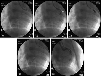
Heparin (for dosing see earlier section) is given either via the arterial sheath or down the catheter into the aortic root before engagement of the coronary arteries. Once the appropriate coronary ostium has been selected, a 0.014″ guidewire is passed to the distal portion of the vessel to be treated. The stent or balloon is passed to the region to be treated over the guidewire using an over-the-wire or monorail technique, and expanded using an indeflator to the desired pressure (typically 8 to 14 atm). Following deployment, all equipment is removed from the vessel and repeat angiography is performed to ensure that there have been no complications. The procedure is illustrated in Figure 9.
Stent deployment in the left anterior descending coronary artery (LAD). A guidewire is passed into the distal LAD (a) and the stent is placed in the proximal vessel. Radio-opaque markers show the edges of the stent (b; arrowheads). The balloon upon which the stent is delivered is inflated to deploy the stent (c) and is then withdrawn. The deployed stent can be clearly seen on fluoroscopy (d) and, following equipment withdrawal, a final angiogram reveals no complications (e). All views are right anterior oblique.

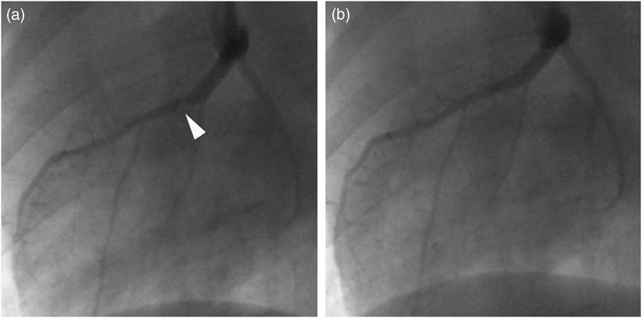
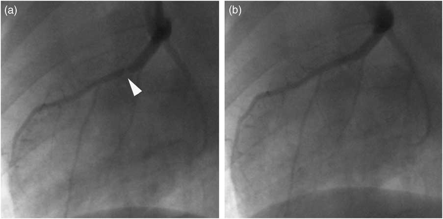
Spasm is quite common in pig coronaries following stent deployment and is generally responsive to GTN (Figure 10). Vessel dissection is rare in the juvenile pig model as the arteries are free of atherosclerosis and therefore more elastic and compliant than are human coronary arteries undergoing PCI typically.
Coronary artery spasm. Following stent deployment in the proximal left anterior descending coronary artery, there is a new apparent stenosis at the distal stent edge (a; arrowhead). This appearance disappears after intracoronary glyceryl trinitrate (b) confirming that this is due to vessel spasm. Both images are left anterior oblique.
Closure
The proximal carotid artery suture is tightened around the sheath, and following sheath withdrawal the artery is ligated. The wound is closed in layers using an absorbable suture. Subcutaneous continuous buried sutures are preferred to reduce the risk of wound infection or dehiscence. We administer an intramuscular opiod (buprenorphine) for post-operative analgesia, although this practice will obviously vary according to standard veterinary practice at individual institutions.
The animal is returned to its enclosure, extubated and allowed to recover from the anaesthetic.
Sacrifice
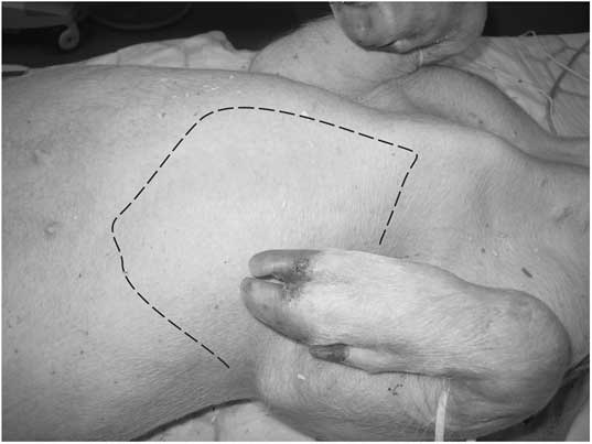
Following induction of anaesthesia, a cannula is placed in an ear vein and a bolus of pentobarbitone (100 mg/kg) is administered. Access to the thoracic cavity can be obtained either via a midline sternotomy using a bone cutter and retractors, or via a left thoracotomy using a scalpel. Figure 11 illustrates the left thoracotomy approach. An incision is made along the left parasternal border through the soft costosternal cartilage and is extended at each end via two intercostal incisions. The rib segment can then be everted to allow easy access to the thoracic cavity.
Left thoracotomy incision.
The visceral and parietal pericardium is stripped from the surface of the heart and the heart is mobilised. Intracoronary stents can be easily identified by gentle palpation. Traction is applied to the heart, avoiding the application of pressure to the stent(s), and the great vessels are cut with scissors allowing removal of the whole heart from the thoracic cavity. It is important, if pressure fixation of the stented vessel(s) is to be performed, that the ascending aorta be removed intact, so that a watertight seal can be created around the fixation catheter. Vessel processing and analysis are beyond the scope of this article, but have been discussed in detail elsewhere (Lowe et al., Reference Lowe, Schwartz, Mac Neill, Jang, Hayase, Rogers and Oesterle2003).
Conclusion
The porcine coronary model remains widely used for investigation of novel therapies before human studies. The systematic description of the techniques required for coronary angiography and intervention should aid investigators wishing to begin using this model, particularly if they have little experience of human coronary procedures, and should serve to minimise animal morbidity and mortality.
Acknowledgements
The authors thank Dr Robert Anderson for giving permission to use the images included in Figure 1.