I. INTRODUCTION
A goal of indentation characterization is to extract the elastic modulus and indentation hardness of materials from load-displacement curves. Given that the basic parameter measured in indentation testing to extract hardness and elasticity is the contact stiffness, the relationship between the contact stiffness and the elastic modulus is of key importance. On the basis of the Sneddon contact solutions without adhesion, Oliver and PharrReference Pharr, Oliver and Brotzen1, Reference Oliver and Pharr2 derived simple contact stiffness relations for a general axisymmetric indenter and hence developed an improved method to measure the hardness and elastic modulus of a material from indentation load-displacement data. The relations have been widely used in indentation characterization.
In the Oliver–Pharr analysis,Reference Pharr, Oliver and Brotzen1, Reference Oliver and Pharr2 the effect of adhesion between the indenter and the material surface is not taken into consideration. The influence of adhesion between contacting surfaces becomes important for smooth surfaces and for biological or soft materials.Reference Schwarz3–Reference Cao, Yang and Soboyejoy5 The incorporation of adhesion in elastic contact was addressed in the Johnson–Kendall–Roberts (JKR) model,Reference Johnson, Kendall and Roberts6 which is now generally used for contact problems with compliant materials. A review of JKR and other adhesive contact models can be found in Ref. Reference Barthel7. Subsequently, on the basis of physical relationships between the adhesive contact and the fracture mechanics, Maugis and BarquinsReference Maugis and Barquins8–Reference Maugis10 extended the JKR model using the Sneddon solutionsReference Sneddon11 to adhesive contacts of general axisymmetric indenters on an elastic half-space. The Maugis–Barquins (MB) solutions can be applied to obtain general relations including adhesive effects for indentation analysis, and results for some specific indenter geometriesReference Yang12, Reference Sirghi and Rossi13, Reference Vallet and Barquins17 have been obtained.
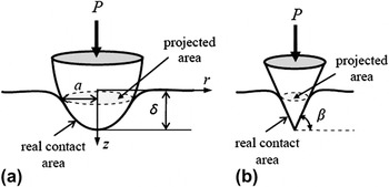
The adhesive contact surface in the MB solutionsReference Maugis and Barquins8–Reference Maugis10 is defined by the projected area of contact between the indenter and the surface (see Fig. 1), not the real area of contact between the surfaces. This difference is not a concern for a flat-ended indenter as in this case, the MB solutions are exact. The MB solutions are also a good approximation for a spherical indenter of large radius.Reference Johnson, Kendall and Roberts6 However, errors may arise for some types of indenter, for example, a sharp conical indenter, in which the difference between the real contact surface and the projected area could be considerable. Therefore, the MB solutions for an adhesive contact should be modified to consider real contact area in the definition of adhesive energy. Such corrections have been undertaken, but only for specific indenter geometries.Reference Yang12, Reference Sirghi and Rossi13 In this article, a more general solution is presented for the contact stiffness of any axisymmetric indenter, and it incorporates adhesion and the real area of interface contact.
(a) Schematic view of the profile formed between a rigid axisymmetric indenter and the surface of an elastic half-space. The real contact area usually differs from the projected contact area. (b) Definition of the angle β for a rigid conical indenter.

The article is arranged as follows. The SneddonReference Sneddon11 and MBReference Maugis and Barquins8–Reference Maugis10 solutions are briefly reviewed first, as these are the basis of the derivations. The MB solutions are then modified by introducing the interfacial energy defined by the real contact area. The modified MB solutions are then used to derive general relations for contact stiffness including adhesion. Finally, for application in indentation analysis, the results of contact stiffness for some specific geometries are obtained.
II. REVIEW OF PREVIOUS DESCRIPTIONS
A. Review of Sneddon solutions for the axisymmetric Boussinesq problem
Consider a normal frictionless contact with no adhesion between a rigid axisymmetric indenter with an arbitrary profile of z = f (r) and an elastic half-space as shown in Fig. 1(a). The shape function can also be written in the form  , in which a is the radius of the projected circular area of the contact surface. The mixed boundary conditions of the contact problem in a cylindrical coordinate system at z = 0 can be described asReference Maugis10, Reference Sneddon11:



where δ is the penetration depth of the indenter tip, σzz (r,0) the distribution of pressure, τrz (r,0) the distribution of shear stress, and uz(r,0) the vertical displacement. The indenter profile shape function should satisfy f (0) = 0. On the basis of the method of Hankel transforms, concise and elegant solutions for the problem were obtained by Sneddon.Reference Sneddon11 The main results of the solutions areReference Maugis10, Reference Sneddon11



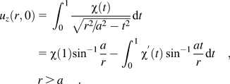
where P is the load, which must be applied to achieve the penetration δ, and the function χ(t) is defined by
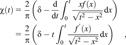
and  is the effective Young’s modulus.
In Sneddon solutions,Reference Sneddon11 the parameter χ(1) is set to be zero to eliminate the singular stress of σzz (r,0) at the edge of the contact, which gives the general solutions for the nonadhesion contact model (denoted by the subscript S) as
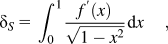

On the basis of the general solutions, the corresponding results for some specific indenter shapes can be obtained.Reference Sneddon11 In particular, Pharr et al.Reference Pharr, Oliver and Brotzen1 verified that the contact stiffness SS based on the nonadhesion contact model is independent of indenter geometry, that is,

where Ap = πa 2 is the projected circular area of the contact surface.
B. Review of MB solutions for adhesive contact
Johnson, Kendall, and RobertsReference Johnson, Kendall and Roberts6 (JKR) studied adhesive contact between a spherical indenter and an elastic half-space. It was shown by Maugis and BarquinsReference Maugis and Barquins8, Reference Maugis9 that the JKR solutionsReference Johnson, Kendall and Roberts6 can be viewed as a Griffith’s model of fracture with the edge of the contact being a crack tip. By applying Sneddon solutions,Reference Sneddon11 Maugis and Barquins successfully extended the JKR model to adhesive contacts of general axisymmetric indenters on an elastic half-space.
In the MB solutions, the total energy UT of the system is UT = UE + UM + US,Reference Johnson, Kendall and Roberts6, Reference Maugis and Barquins14 where UE and UM are the stored elastic energy and the mechanical potential energy change due to the applied load, respectively, and US is the interfacial energy, expressed as US = −γAp, where γ is the interfacial energy per unit area.Reference Maugis and Barquins14, Reference Tabor15 Solutions for adhesive contact can be obtained under the equilibrium condition dU T = (Gp−γ)dAp = 0, where
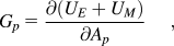
is the energy release rate with the dimensions of energy per unit projected area.Reference Maugis and Barquins8–Reference Maugis10 When adhesion is present, the parameter χ(1) in the Sneddon solutions can be nonzero, implying that singular contact stresses arise at the contact edge. Therefore, there is a connection between the parameter χ(1) and the stress intensity factor KI in fracture mechanics, which can be determined from Eq. (3) asReference Maugis and Barquins8–Reference Maugis10, Reference Vallet and Barquins17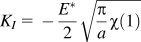 . Further, the relationship between the strain energy release rate Gp and the stress intensity factor KI is given byReference Lawn16
 . This establishes a link between Gp andχ(1). Let P 1 be the apparent load that, if χ(1) = 0, gives the same contact radius as that observed under load P with χ(1) ≠ 0 (P 1 > P).Reference Johnson, Kendall and Roberts6, Reference Maugis and Barquins8–Reference Maugis10 Using Eqs. (1) and (2),


The energy release rate Gp can thus be expressed as

and the load P in MB adhesive contact solutions can be obtained by the equilibrium condition Gp = γ.Reference Maugis and Barquins8–Reference Maugis10, Reference Maugis and Barquins14
III. MODIFICATION OF MB SOLUTIONS
A. Solutions incorporating real area of contact
The interfacial energy in both JKR and MB solutionsReference Johnson, Kendall and Roberts6, Reference Maugis and Barquins8–Reference Maugis10 is defined by the projected circular area Ap = πa 2 of the interfacial contact area as shown in Fig. 1. Below, the MB adhesive contact solutions are modified by incorporating the interfacial energy using the real interfacial contact area.
When real contact area is considered, the interfacial energy US is written as

where A is the real contact area of the two surfaces, rather than the projected circular area Ap. Solutions for adhesive contact can be obtained under the condition dUT = (G−γ)*dA = 0 , where  is the energy release rate per unit contact area. However, to make use of the formulas adopted in the Maugis and Barquins derivations,Reference Maugis and Barquins8–Reference Maugis10 the condition dUT = 0 can also be expressed as

where Gp is given in Eq. (9). For an axisymmetric indenter with profile shape function z = f(r), we have  and dAp = 2πrdr. The ratio
 at r = a thus can be expressed as
 . Therefore, the equilibrium condition [Eq. (14)] is equivalent to

where κa is the indenter geometry parameter given by

Therefore, for modeling real interfacial contact area, the balance condition to determine the adhesive contact solutions is modified to Eq. (15), rather than Gp = γ. It is noted that the relations reduce to the MB model if κa = 1, that is, if the projected circular area Ap is used in Eq.(13).
By substituting Eq. (12) into the new equilibrium condition [Eq. (15)], the modified MB relationship between P and a at equilibrium is given by

This relation can be simplified to

where

is the adhesion force, and P1 is given by Eq. (10).
By considering the real adhesive contact area, the value of the parameter χ(1) is modified by Eqs. (11) and (17) as 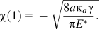 By substituting this value into the general solution Eq. (1), the modified penetration depth of the indenter is

with

where δ 1 is the indenter tip displacement in nonadhesion contact, and δγ is the indenter tip displacement due to adhesion effects.
Comparing the relations obtained in this section, we observe that the MB solutionsReference Maugis and Barquins8–Reference Maugis10 are modified by the parameter κa introduced into the interfacial energy related terms, that is, Pγ in Eq. (19) and δγ in Eq. (21). For κa = 1, the relations reduce to the MB solutions,Reference Maugis and Barquins8–Reference Maugis10 and with no adhesion (γ = 0), δ and P reduce to the Sneddon solutions Eqs. (6) and (7).
B. Solutions for contact stiffness including adhesion effects
In this section, the general relation of contact stiffness including adhesion is derived on the basis of the modified MB solutions. The contact stiffness in indentation is defined as  . Noting that the parameter κa in Eq. (16) is a function of the radius a of the projected circular area, Eq. (17) gives

in which  can be determined from Eq. (10). Following the treatment of Pharr et al.Reference Pharr, Oliver and Brotzen1
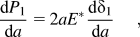
where
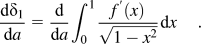
From Eqs. (20) and (21),  can also be expressed as

By substituting Eqs. (25) and (23) into Eq. (22), we obtain

Hence, the general relation of contact stiffness including adhesion effects can be found from Eqs. (26) and (25) as
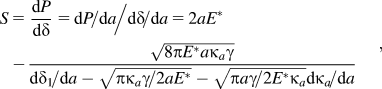
where  is given by Eq. (24). Note that both δ 1 and κa, and hence the contact stiffness, depend on the indenter geometry f(x). Eq. (27) can also be written as

with

Again, with no adhesion (Sγ = 0), Eq. (28) reduces to the Sneddon contact solution Eq. (8), and for κa = 1,  , which is the MB solution.Reference Maugis and Barquins8–Reference Maugis10
IV. RESULTS FOR SPECIAL CASES
In this section, we apply the general solutions obtained to some specific indenter geometries.
For a flat-ended cylindrical indenter with radius a, the contact area is the circular area πa 2. Since the shape function of the flat indenter is  , we have κa = 1 and P 1 = 0. The pull-off (adhesive) force and the corresponding displacement induced thus can be determined from Eqs. (17) and (20) as
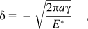

These results are identical to those calculated by Kendall.Reference Kendall18, Reference Yang19 Since the radius a is constant for a flat-ended cylindrical indenter, the contact stiffness  is

which is independent of the interfacial surface energy γ.
For a spherical indenter with a ≪ R, where R is the radius of the sphere, the shape function can be approximately expressed by an ellipsoidal function asReference Maugis10

Substituting Eq. (33) into Eq. (16) gives

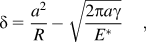
The penetration, contact force, and contact stiffness obtained from Eqs. (20), (17), and (27) give the well-known JKR solutions,Reference Johnson, Kendall and Roberts6, Reference Barthel7, Reference Yang20


With no adhesion (γ = 0), δ and P in Eqs. (35) and (37) reduce to the Hertz contact solutions.Reference Hertz, Jones and Schott21, Reference Barthel7
For a conical indenter with a semivertical angle β [see Fig. 1(b)], the surface profile isReference Maugis10

Substituting Eq. (38) into Eq. (16) gives

and inserting Eqs. (38) and (39) into Eqs. (20), (17), and (27) gives the penetration, contact force, and contact stiffness,
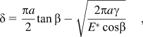
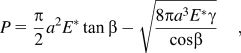

The results [Eqs. (40)–(42)] are identical to those obtained by YangReference Yang12 for the case of frictionless contact with a conical indenter, also using the real contact area for interfacial energy. The only difference here is that a simpler derivation is followed and the solutions are general for axisymmetric indenters.
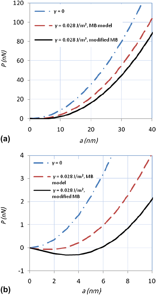
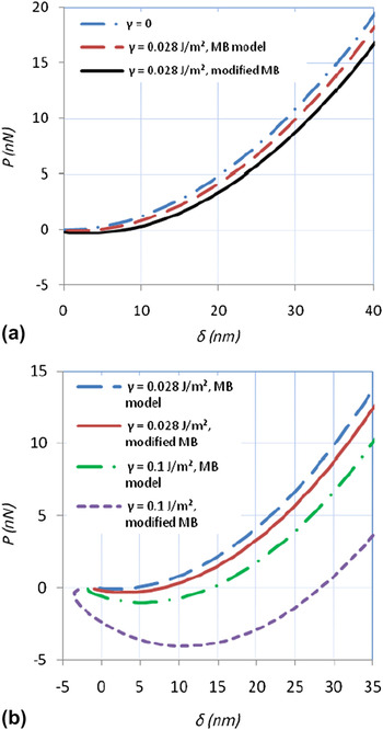
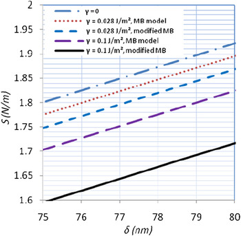
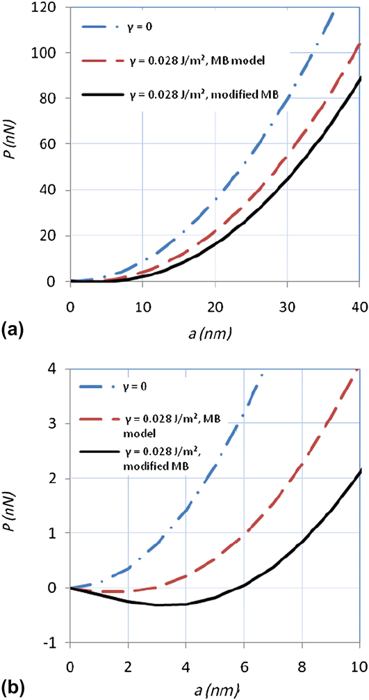
It is apparent from Eqs. (40)–(42) that for a sharp conical indenter, such as an atomic force microscopy (AFM) tip, cos β can be much smaller than one and the differences between model solutions may be significant. Figures 2–5 give an indication of the magnitude of such differences by showing numerical comparisons between the MB solutions and the newly modified MB solutions for a rigid conical indenter. To cross-check the results with those of Yang,Reference Yang12 in the examples chosen, the half-space material studied is poly-dimethyl-siloxane with material properties of E = 24.5 MPa, ν = 0.5, and yield stress is ∼2.5 MPa. Figure 2 compares load P versus radius of projected area by an indenter with β = 60° and γ = 0.028 J/m2 for the different models. There are two regimes of most interest. For indentation measurement of hardness and elasticity, the unloading response at high applied load [Fig. 2(a)] is required.Reference Fischer-Cripps22 For the modified MB solution, a larger radius evolves compared to the MB solution for the same peak load. The behavior at low loads [Fig. 2(b)] describes a regime of interest in AFM experiments, and here a large difference is observed between models, with a deeper and broader adhesion region for the modified MB solution. This is not surprising given that the area used in the interfacial energy term for the modified MB theory is larger in comparison to the projected area of the standard MB solution. The data can be plotted in the more familiar form of load versus indentation depth (Fig. 3), from which similar conclusions in the low- and high-load regimes can be drawn. Figure 3(b) highlights again the large influence of the interfacial energy term γ at low loads, with increasingly large differences between the models as γ increases from 0.028 to 0.1 J/m2; however, one should always note that the error in γ itself is uncertain because of the difficulty in determining γ experimentally.Reference Olah and Vancso23
(a) Variation of radius (a) of projected area with load (P) for a rigid conical indenter (β = 60°) for the Sneddon (γ = 0), the MB (γ = 0.028 J/m2), and the modified MB (γ = 0.028 J/m2) models. The half-space material parameters are E = 24.5 MPa and ν = 0.5, similar to poly-dimethyl-siloxane. (b) A close up of the low load region of (a).
(a) Variation of indentation depth (δ) with load (P) for a rigid conical indenter (β = 60°) for the Sneddon (γ = 0), the MB (γ = 0.028 J/m2), and the modified MB (γ =0.028 J/m2) models. The half-space material parameters are E = 24.5 MPa and ν = 0.5, similar to poly-dimethyl-siloxane. (b) A close up of the low-load region of (a) with additional data shown for the case γ = 0.1 J/m2.

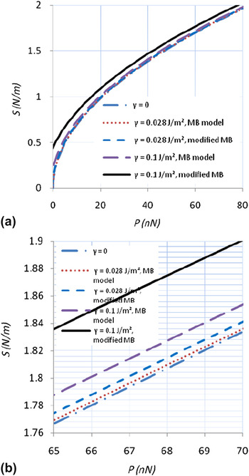
(a) Variation of contact stiffness (S) with load (P) for a rigid conical indenter (β = 60°) for the Sneddon (γ = 0), the MB, and the modified MB models. The half-space material parameters are E = 24.5 MPa and ν = 0.5, similar to poly-dimethyl-siloxane. Two values of interfacial energy are shown (γ =0.028 J/m2 and γ = 0.1 J/m2). (b) A close up of the high-load region of (a) showing differences in contact stiffness between the models, which, in turn, influence the calculation of material hardness and elasticity.

Variation of contact stiffness (S) with indentation depth (δ) in the high load regime for a rigid conical indenter (β = 60°) for the Sneddon (γ = 0), the MB, and the modified MB models. The half-space material parameters are E = 24.5 MPa and ν = 0.5, similar to poly-dimethyl-siloxane. Two values of interfacial energy are shown (γ = 0.028 J/m2 and γ = 0.1 J/m2).

The material elasticity and hardness are calculated from the measured stiffness at high load.Reference Fischer-Cripps22 Accordingly, Figures 4 and 5 compare the stiffness for the MB and modified MB models. The stiffness changes nonlinearly as a function of load [Fig. 4(a)] with the numerical difference between the two models increasing as the load decreases. At high load [Fig. 4(b)], the curves show approximately constant difference at fixed load between the MB and the modified MB models of ∼1.4% for γ = 0.028 J/m2 and ∼2.7% for γ = 0.1 J/m2. The corresponding high-load data for a fixed penetration depth (Fig. 5) shows differences between the models of ∼1.7% for γ = 0.028 J/m2 and ∼5.6% for γ = 0.1 J/m2.
Similar numerical calculations using E = 24.5 MPa and ν = 0.5 were undertaken for a shallower conical indenter with β = 19.7, that is, a Berkovich’s type analogue. As expected, as β becomes small, the difference between the MB and the modified MB results decreased to a negligibly small value at high applied load (a ∼0.15% difference in contact stiffness for γ = 0.1 J/m2). Large differences between the models can exist at loads near zero (a ∼5% difference in contact stiffness for γ = 0.1 J/m2), but in practice the Berkovich indenter would not be used in the low-load regime. Finally, simulations for a hard material with E = 20 GPa (data not presented) show the difference between the models, which is negligible, irrespective of the value of γ. Thus, for a conical indenter at fixed load or fixed penetration depth, the differences between the MB and modified MB models for high-load indentation experiments are only significant (within a few percent) if γ is large (∼0.1 J/m2), β is large (∼60°), and E is small (≤100 MPa).
V. CONCLUDING REMARKS
The MB solutionsReference Maugis and Barquins8–Reference Maugis10 for the adhesive contact between an axisymmetric indenter and an elastic half-space were modified to incorporate the interfacial energy defined by the real contact area. The solutions obtained are general for axisymmetric shaped indenters. Hence, the contact stiffness including adhesive effects was derived for use in indentation analysis and relations for some known indenter geometries (flat, sphere, and cone) shown. Numerical calculations showed that the difference in expected stiffness for the modified MB model compared to the standard MB results can be significant at low loads of interest in AFM measurements and is a ∼3% effect for conical indenters at high loads if γ is large (∼0.1 J/m2) and the material is soft (E ≤100 MPa).
The advantage of the general solutions given is that adhesive contact for any axisymmetric indenter can be analyzed. For comparison purposes, only known results for the flat, spherical, and conical indenter geometries have been presented. However, adhesive contact solutions for other axisymmetric indenters such as paraboloid or ellipsoid of revolution can be obtained in a similar manner. The general solutions may also be applied to study the importance of adhesion and indenter tip shape at low loadsReference Korsunsky24 and to extract mechanical properties of soft materials or nanostructures probed by AFM with different tip shapes.Reference Dimitriadis, Horkay, Maresca, Kachar and Chadwick25, Reference Withers and Aston26 Finally, the general solutions can be used to investigate the application range of various approximate solutions. For example, the JKR model for a spherical indenter is based on the assumption a ≪ R. However, when a is comparable to R, the exact shape function  should be used to obtain the general adhesive contact solutions. These applications will be studied in a subsequent paper.