I. INTRODUCTION
Weather radar is an important source of information for air traffic control and, in general, for meteorological services and research of the environment. For retrieval of parameters on the water content of clouds it is important to measure the full backscatter matrix (BSM) of clouds, with a highly detailed analysis of the Doppler shifts. Currently, various radars are capable of measuring the BSM, but the waveforms used mostly consist of transmitting sounding signals in two orthogonal basis directions alternating. So in order to measure the full BSM at least two consecutive transmissions are needed. By consequence, some time has passed in between the two transmissions and due to the decorrelation of the echoes of the hydrometeors the quality of the parameter retrieval is somewhat compromised. The NOAA/National Severe Storms Laboratory (NSSL) in the USA has done extensive experimental research on the benefits of polarimetry in weather radar. Scharfenberg et al. [Reference Scharfenberg1] provide a review of the results achieved. NSSL operates a research radar designated KOUN based on simultaneously transmitted horizontally and vertically polarized pulses to explore new frontiers in weather observation. Polarimetry is among these [Reference Zrnić, Zahrai, Torres, Ivic, Curtis and Melnikov2]. To the best knowledge of the authors, the current article is the first one addressing the use of orthogonal frequency division multiplexing (OFDM) for a fully polarimetric weather radar.
The research addressed in this article explores orthogonal signals, such that the sounding signals in the two orthogonal basis directions can be transmitted at the same time. As a result, the BSM can be measured using a single – though complicated – transmission. Also in [Reference Giuli, Fossi and Facheris3] the measurement of the BSM using orthogonal signals has been addressed.
IRCTR has developed a radar platform called PARSAX (polarimetric agile radar in S- and X-band; currently the radar is being set to work in S-band) supporting to do such analyses with a variety of waveforms [Reference Krasnov, Ligthart, Li, Lys and van der Zwan4]. In [Reference Babur5, Reference Babur, Krasnov and Ligthart6] the problem of simultaneous transmission of orthogonal signals has been addressed using various modes of frequency modulated continuous wave modulation. The current article explores a particular phase coded waveform, OFDM. It will be demonstrated that such waveforms can be used, albeit with a number of constraints.
OFDM is widely used in communication [Reference Prasad7]. It is being considered for application in radar only recently [Reference Levanon8], inspired by the availability of signal generators due to the application in communication. A typical property of OFDM is that the susceptibility to Doppler shift has to be considered with care. This susceptibility depends, among other parameters, on the spacing between the individual carriers composing the OFDM signal. An analysis of such susceptibility and also of other properties of OFDM in its application for radar can be found in [Reference Tigrek9]. Whereas Tigrek [Reference Tigrek9] addresses wideband signals, also ultra-wide band signals based on OFDM are explored, for instance in [Reference Garmatyuk and Brenneman10]. It should be noted that the parameters of these waveforms are chosen such that the (pulsed) signal is quite robust against Doppler shift.
The article is structured in the following way. Section II will detail the OFDM sounding signal both in a generic way and in the specific coding that is used for the benefit of the isolation of the two orthogonal components. Section III discusses a set of parameters applicable to this type of weather radar. Section IV addresses the effects of Doppler shift. Doppler shift is a parameter that is of vital relevance for the retrieval of the cloud parameters. However, in OFDM any Doppler shift can be the major cause of loss of orthogonality. Section V presents a brief discussion of the results, followed by the concluding Section VI.
II. SIGNAL DESCRIPTION
The OFDM signal is composed of a number of carriers at a mutual, constant spacing that is the inverse of the signals' duration. The complex baseband description is

where N is the number of carriers, a k is the complex amplitude of carrier k (also called the code of the carrier), and Δf is the frequency spacing between the carriers. T is the duration of the signal, T = 1/Δf.
All carriers composing this signal are orthogonal. This orthogonality follows from the fact that
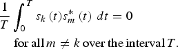
Here s m(t) represents the mth carrier and the asterisk denotes the complex conjugate. Orthogonality of the carriers includes that each of them can be modulated independently with its own carrier code ak as in equation (1).
In our case the duration T of the signal is quite long and therefore some type of pulse compression is applied in order to achieve an appropriate range resolution. Given the nature of the OFDM signal, the most widely known procedure is to transform the received signal to the frequency domain and multiply the carriers by the complex conjugate of the Fourier transformed transmitted signal. Then after this multiplication the time domain range profile is generated by the inverse Fourier transform. The level of the sidelobes in this range profile can be managed by any weighting technique.
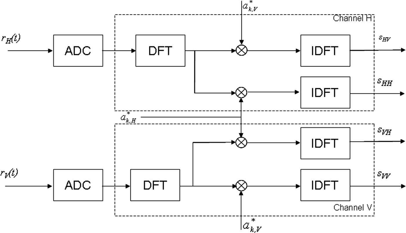
The signal processing for the OFDM signal in radar application consists basically of the matched filter processing to generate the range profiles. The range processing of the fully polarimetric radar can be decomposed into four processing branches; each processing branch is responsible for one element of the polarimetric BSM. The processing can conveniently be implemented in the frequency domain to reduce the computational complexity. The overall range processing scheme is illustrated in Fig. 1.
Processing Scheme for the OFDM signal.
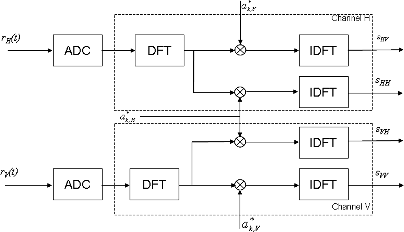
Each of the two received signals r V(t) and r H(t) from the two orthogonal vertical and horizontal polarization probes of the antenna, respectively, includes both cross-polar and co-polar information. These two analog signals are converted into discrete digital sequences by the analog-to-digital converter, as expressed in Fig. 1.
The first processing step after the analog-to-digital conversion can be considered as the demodulation of the OFDM signal by a discrete Fourier transform (DFT).
In the following step, the signals from the two receiving channels are each processed in two branches. Taking the processing channel of r H(t) as an example, the frequency domain discrete sequence is multiplied by the complex conjugates of the sequences of a k,V and a k,H, respectively. The discrete sequences a k,V, a k,H, k = 0,1, … , N − 1 and the modulated sequence a k, k = 0,1, … , N − 1 have the following relation:
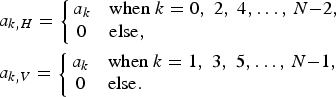
This waveform is further designated as “interleaved OFDM” (I-OFDM).
The range processing is completed by the inverse DFT operation; the overall four-channel outputs are the range profiles matrices for each sweep-to-sweep-based measurement. The estimation of the BSM can then be completed by the estimation of the target distance and the Doppler shift.
As can be seen from this description, in the receiver connected to the horizontally polarized probe of the antenna both the co-polarized and the cross-polarized signals will be present. The cross-polarized signal represents the cross-polarized elements of the BSM. Normally these cross-polarized signals have a significantly lower power than the co-polarized signals. Both signals are present simultaneously. In order to separate them, two range profiles are generated by using the carrier code sequences a k,H and a k,V, respectively, in separate processing branches. After the range profiling, the cross-compressed signal, i.e. the signal in one branch after application of the code of the signal of the other branch, will be noise-like. The resulting average signal power is called here the leakage of the codes (the isolation of the codes would be the inverse of the leakage).
The transmission scheme for the fully polarimetric radar is quite simple. The carrier code sequences are generated, modulated by using a DFT, and mixed to the carrier frequency. These operations are executed in two parallel tracts, one feeding the horizontally polarized and the other one the vertically polarized probe of the antenna.
According to this line of thinking, two signals used for the experiments for the fully polarimetric radar are defined:
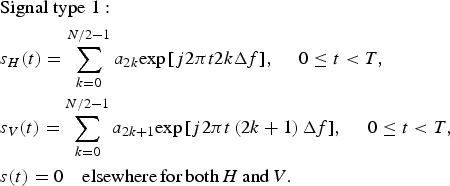
Here s V(t) represents the sounding signal exciting the vertical polarization and s H(t) the horizontal polarization.
This is the signal as discussed above. The carrier codes a 2k correspond with either a k,H or a k,V in equation (3). The codes a 2k+1 correspond with the other one.
The second signal is defined as
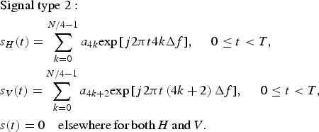
The difference between the signals type 1 and type 2 is in the sparsity of the spectrum occupancy of the signal. In type 1 the even frequencies are on the horizontal exciter of the antenna, whereas the odd frequencies are fed to the vertical exciter. The number of active carriers in each of the polarizations thus is N/2. So both sounding signals have a one-out-of-two frequency spectrum occupancy with respect to the regular fully populated OFDM power spectrum. In type 2 the spectrum occupancy is sparser, since there in each of the polarizations every one-out-of-four frequencies is active, while the frequencies fed to the horizontal exciter are shifted by two Δf intervals with respect to the vertical exciter.
An important side effect of this way of coding is that the unambiguous range is reduced compared to the value of the full set of carriers. This can be seen by rewriting the signal type 1 as
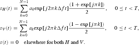
From this equation it can be seen that the horizontally polarized sounding signal is composed of two peaks. Both of them are at half the amplitude of the signal corresponding with the fully populated set of carriers, while one of them is shifted in range by half the unambiguous synthesized range interval. The same holds for the vertically polarized sounding signal, however with a 180° phase shift for the shifted peak compared with the horizontally polarized signal.
A similar expression can be developed for the signal type 2:
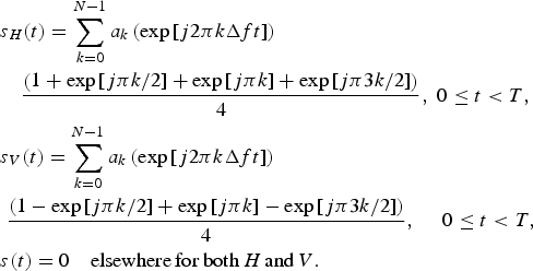
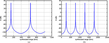
So the reduction of the unambiguous range interval is by a factor of two for the type 1 and by a factor of four for the type 2 signal. Figure 2 shows examples of the range profiles for both types of signal. In order to maintain the same unambiguous range, the carrier frequency spacing therefore should be reduced to 1/2 or 1/4 of the value for the fully populated spectrum. As a consequence the total duration of the signal will be extended by a factor of 2 and 4, respectively, thus also compensating for the otherwise reduced total power. In order to align the unambiguous range intervals in Figs 2(a) and 2(b), the carrier spacing used in Fig. 2(b) is half the value of the one used in Fig. 2(a).
Examples of the synthesized range profiles for the signals types 1 and 2. (a) Signal type 1, scenario: single target at 0.125 of the maximum range of 1024 bins. (b) Signal type 2: Single target at 0.125 of the maximum range of 2048 range bins.

The carrier codes a k have an important impact on the signal envelope in the time domain to the extent that the ratio between the peaks and the average of the power is affected. Certainly, the envelope is not constant and the transmitter cannot be driven into saturation as it is usual in radar. This could be a reason for radar engineers to be reluctant to apply this type of waveform. Special coding strategies have been devised to optimize the peak to average power ratio [Reference Levanon8, Reference Schroeder11].
One of the comments on the Doppler sensitivity of the OFDM signal is that as soon as the Doppler shift is no longer very small compared to the carrier frequency spacing, the sidelobes of the compressed signal come up rapidly and the orthogonality is lost. When the carrier codes are independent random variables, the variance of the sidelobes will be 1/N in the case of relatively large Doppler shifts. In the zero-Doppler case the sidelobes of the range profile after compression can be managed using any of the well-known weighting functions. The signal in the time domain before the compression will show a noise-like envelope, as extensively discussed in [Reference Levanon8]. When on the contrary, the carrier codes are chosen to be equal, the loss of the sidelobes will be negligible, but the peak to average power ratio of the signal before compression will be equal to N, so the signal envelope will be strongly peaked.
III. A SET OF PARAMETERS FOR WEATHER RADAR
In the application of weather radar as described in the introduction, a high resolution of the radial speed is needed, a typical value being Δv r = 0.1 m/s. For an X-band radar, this corresponds to a Doppler resolution of 6.6 Hz and thus on a time interval of evaluation of the phase of 0.15 s. In order to appreciate the significance of the Doppler resolution, let us develop a benchmark set of radar parameters compliant with this requirement.
A) Signal type 1
For the application of detailed weather measurements using the X-band radar, the maximum range should be not less than 10 km. Since in OFDM the maximum unambiguous range corresponds to R u,max = c/2Δf, and given the effect of the odd/even coding, this translates into a carrier frequency spacing Δf < 7500 Hz. Because the duration of this carrier spacing is directly linked to the time duration of the signal by T = 1/Δf = 1.33 × 10⁻⁴ s, also the pulse repetition frequency is an immediate consequence, PRF = 7500 Hz. Hence, using a Doppler filterbank, the number of pulses to be integrated in order to arrive at the required Doppler resolution is N p = 0.15 × 7500 = 1125.
The number of carriers affects two parameters at the same time: the bandwidth, B = N fΔf, and the sidelobes of the pulse compression in case of too high a Doppler shift, so in case of loss of orthogonality, SLL = 2/N f (the number of active carriers is N f/2 in both the odd and the even channels). The range resolution of weather radar is a compromise between sensitivity (given the number of rain droplets per resolution volume) and detail in finding the structure of clouds. A fair number is to assume that it should not be lower than 3 m, hence B = c/(2ΔR) = 50 MHz and the corresponding number of carriers is N f = B/Δf = 50 × 106/7500 = 6667. The correlation noise floor, which is the mean value of the sidelobes of the pulse compression in the case of total loss of orthogonality is SLL ≈ −35.2 dB.
B) Signal type 2
Along the same line of reasoning as in Section III.A, the frequency spacing should be Δf < 3750 Hz, in order to maintain the unambiguous range longer than 10 km. The corresponding duration of the signal is 0.2667 ms. During the time interval of evaluation of the phase of 0.15 s (refer to the introduction of this section) the number of transmitted pulses is N p = 0.15/0.2667 × 10−3 ≅ 562. The number of carriers follows from N f = B/Δf = 13333. The number of active carriers in both the vertical and horizontal polarization is N f/4 = 3333, leading to the same value of the correlation noise floor as for the signal type 1.
IV. THE EFFECTS OF DOPPLER SHIFT
The concept of orthogonality of the various carriers in the OFDM waveform is compromised if the carriers are shifted due to Doppler. In communications this effect is called inter carrier interference. Effectively the impact of Doppler shift depends on the ratio of the Doppler shift to the frequency spacing between the carriers. In case of randomly phase coded carriers, the pulse compression in the receiver will fully fail as soon as the Doppler shift equals the carrier spacing.
Because of the same reason of loss of orthogonality, also the code leakage is affected by Doppler shift and it is getting higher the higher the ratio between Doppler shift and carrier spacing is.
In the case of fully random carrier phase coding, the correlation noise floor is described by [Reference Tigrek9]

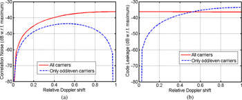
Here υ = f d/Δf is the ratio between the Doppler shift and the carrier spacing. This expression is valid for the fully occupied set of carriers. A graphical representation is in Fig. 3(a), while in Fig. 3(b) the code leakage is presented as a function of the relative Doppler shift υ. In these graphs also the corresponding graphs are shown for the odd/even carriers waveform.
Comparison of the correlation noise and the code leakage of the two full sets of carriers (solid lines) and the signal type 1 (dashed lines): (a) correlation noise and (b) code leakage.

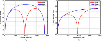
In order to compare the signal types 1 and 2 Fig. 4 shows the code leakage and the correlation noise level, however as a function of the absolute Doppler shift.
Illustration of the correlation noise and the code leakage prevailing at the signals type 1 and type 2. (a) Level of the correlation noise w.r.t. the maximum found in the compressed co-polar channel. (b) Code Leakage in the cross-polar channel w.r.t. the maximum in the co-polar channel.

It can be seen that for low Doppler shifts, the difference between the figures of merit is not significant, while for bigger shifts the correlation noise for type 2 is lower and the code leakage as well. The maximum of the compressed pulse is affected by the Doppler shift as well, in particular for the signal type 2.
These graphs demonstrate two major effects: the correlation noise and the code leakage.
A) Effects on the correlation noise floor
The correlation noise, consisting of the range sidelobes in the co-polar channel due to the Doppler shift, is very low for low Doppler shift. More precisely, if the Doppler shift would be exactly zero, the profile of the range sidelobes would correspond to the weighting function used in the pulse compression. Just off the zero Doppler values, the waveform using all carriers has a slightly lower correlation noise floor than the odd/even carriers waveform (type 1), as a consequence of the higher number of carriers. In all other cases, composing the greater part of the span of Doppler values, the odd/even waveform is superior.
B) The code leakage
Regarding the code leakage, consisting of the signal of one tract (the “source”) leaking into the other tract (the “victim”) and there compressed using the code of the victim tract, the odd/even waveform is superior to the waveform with all carriers used for the Doppler shifts of interest. Obviously, this was the reason why this waveform was devised. Such a property is extremely important. It supports to effectively filter away the strong echoes from stationary ground objects, that otherwise might clutter the meteorological echoes.
It should be reminded though that at system level the total leaked power from one channel into the other channel is not just due to code leakage, but also due to other system components, e.g. the antenna. A typical number for co-/cross-polar antenna isolation is 25–30 dB for parabolic antennas. Calling I A the antenna co-/cross-polar isolation and I C the code leakage, preferably the inequality S max + G p − I A − I C < Nt should hold (all values in dB). Here S max is the maximum signal that is within the linear dynamic range of the receiver, Gp is the gain due to the processing, and Nt is the level of the thermal noise. Using for instance S max = 70 dB with respect to thermal noise, G p = 10log(1125) = 30.5 dB (for signal type 1), I A = 30 dB then it follows I C < 70.5 dB. Such a value is achieved for Doppler shifts close to zero for both the signals of type 1 and type 2, but not for |f d| > 100 Hz ∝ 1.5 m/s. Thus stationary discrete objects, also if some internal motion is present, do not pose a problem. Hydrometeor echoes themselves will be much weaker than the discretes and do not pose a problem either.
V. DISCUSSION
Using OFDM-coded waveforms tailored to minimize the leakage of signals from one channel out of two orthogonally polarized channels into the other one is considered to be very promising. Such coding outperforms any other type of coding identified so far on the figure of merit for the codes. Apart from the straightforward coding as shown by the two types of signal in this paper, also other codes can be devised, always based on the orthogonality of the carriers in the waveform.
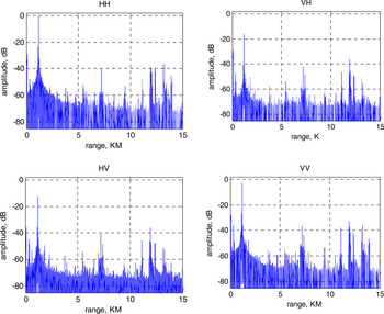
A recent experimental result obtained using the PARSAX radar for the simultaneous transmission of an odd/even coded pair of OFDM signals as in equation (3) is shown in Fig. 5. It shows the range profiles of each of the four elements of the BSM for a single OFDM sweep. The number of carriers is N = 50 000 and the total bandwidth is B = 50 MHz. The carriers are random QPSK coded. The antenna is pointing at the horizon while the weather was clear. The reflections in this example therefore only concern ground objects. The vertical scale is adjusted to have the highest value (actually the object concerned is a tall chimney) at 0 dB. The floor of the signal level is close to the dynamic range of the receiver, approx. 70 dB. More details are in [Reference Wang, Tigrek, Krasnov, van der Zwan, van Genderen and Yarovoy12].
Range profiles of the four elements of the BSM. The polarization basis is linear, V/H.

The limit of applicability of the coding comes from the loss of orthogonality, as it can be caused for instance by the Doppler effect. Waveforms such as linear frequency modulation are far more tolerant to Doppler, but cannot provide the isolation between the codes as discussed here unless the orthogonal signals are timed in a partially overlapping order, like proposed in [Reference Babur, Krasnov and Ligthart6].
An effect that has not been addressed in this paper, but that is highly important for keeping the carriers orthogonal while receiving echoes with an unknown delay, is the necessity to introduce a cyclic prefix as an extension to the duration T of a single pulse. This effect has been discussed in detail in [Reference Tigrek9]. It does not invalidate the conclusions.
In this article the orthogonality of codes was exploited for the benefit of measurement of the BSM in fully polarimetric radar. The concept of orthogonality might also be used in different applications, for instance for the benefit of retrieving the echoes from multiple beams generated by phased array antennas.
VI. CONCLUSIONS
The waveform based on I-OFDM with a sparsity of one-out-of-two carriers per polarization channel offers interesting opportunities for a fully polarimetric radar. The parameters of such a waveform for acquisition of parameters of weather have been explored, and an initial experiment with real-life data has shown that the waveform seems a credible candidate for this application. Maybe other applications can benefit from such a waveform as well, but these are outside the scope of this article.
 Piet van Genderen graduated from the University of Twente in Enschede, The Netherlands in 1971. He worked with the National Aerospace Laboratory in Amsterdam until 1979. He then moved to Hollandse Signaalapparaten, now Thales Nederland, where he held several positions in R&D. In 1994 he was also appointed as full professor at the Delft University of Technology. He holds several patents and (co-)authored about 200 publications. He was three times awarded with the prize for the paper that best advances the state-of-the-art in radar at the European Radar Conference. He holds an honorary doctorate of the MTA of Bucharest, Romania. His main research interests are in the design of waveforms and associated algorithms for extracting object features.
 Oleg Krasnov received the M.S. degree in radio physics from Voronezh State University, Russia, in 1982, and the Ph.D. degree from National Aerospace University “Kharkov Aviation Institute,” Ukraine, in 1994. In 1999, he jointed in the International Research Center for Telecommunications and Radar (IRCTR), TU Delft. His interests are in the field of algorithms development for polarimetric radar signal and data processing, multi-sensor atmospheric remote sensing.
 Zongbo Wang was born in Shandong, China, in 1982. He received the B.S. and Ph.D. degrees in electronic engineering from Beijing Institute of Technology, Beijing, China, in 2004 and 2009, respectively. In 2007, he joined Group of Microwave and Radar, Universidad Politécnica de Madrid, Madrid, Spain, where he is engaged in high-resolution LFM-CW radar image processing. In 2009, he joined the International Research Centre for Telecommunications and Radar, the Delft University of Technology, Delft, Netherlands, for the research of polarimetric remote sensing. His interests are in the field of radar signal processing, real-time digital signal processing, sub-band theory, and filter bank.
 Recep Fırat Tigrek was born in Antalya, Turkey, in 1981. He received his B.Sc. and M.Sc. degrees from Middle East Technical University in Ankara, Turkey in June 2002 and August 2005, respectively. In 2006 he joined Thales Nederland as Marie Curie Fellow, and became a Ph.D. candidate at the International Research Center for Telecommunications and Radar (IRCTR) at the Delft University of Technology in Delft, the Netherlands, where he received the Ph.D. degree in 2010. His research interests are focused on radar waveform design and signal processing.