Introduction
Substrate integrated waveguide (SIW) is a simplest and new type of transmission line technology that permits to incorporate traditional non-planar rectangular waveguide components in a planar form. A SIW consists of a piece of the printed circuit board (PCB), bounded by closely spaced metallic posts so that nourishing fields can be controlled inside the substrate [Reference Xu, Bosisio and Wu1, Reference Deslandes and Wu2]. It has good shielding between outside and inside, hence avoiding radiation loss and parasite radiation due to feeding assembly [Reference Bozzi, Georgiadis and Wu3]. PCB and low-temperature co-fired ceramic are compatible with SIW technology [Reference Wu and Kishk4]. This technology also allows integration of antennas with active as well as passive components in a solitary substrate. Limited researches based on SIW fed antenna are available in the literature; however, most of the available designs are either bulky or suffering from low gain [Reference Kumar, Dwari, Singh and Agrawal5–Reference Cheng, Yao, Yu and Chen8]. Thus, the compact antenna with high gain for multiband applications is still very inspiring. Dielectric resonator antenna (DRA) can be a suitable candidate for such applications or modern wireless communication systems. DRA is commonly made of high permittivity (3 < εr < 30) lossless ceramic materials, which is called dielectric resonators (DRs). It has the low-temperature coefficient of frequency and zero conductor loss which is the main foundation for the high radiation efficiency. Due to the 3D structure, DRs provide more degree of freedom during the optimization and analysis of antenna characteristics.
In our previously published work [Reference Kumar, Dwari, Singh and Agrawal5], a technique to achieve the triple band has been demonstrated by using SIW resonator feed DRA. The gain of an antenna element can be increased by using an electromagnetic band gap (EBG) structure, by the loading of metamaterial or by integration of horn reflector. The main drawback of EBG and metamaterial structures is their dependency on frequency-selective mechanism, which restricts to design a high gain antenna with better gain flatness over the wideband and multiband.
In this paper, horn-mounted cylindrical DRA is analyzed for high gain with triple band applications, fed by SIW resonator. Plastic-based conical horn is developed using the additive 3D printing technique and taped it sticks with copper strips (adhesive tape). The same horn is used to enhance the gain of DRA. Selective bands are achieved at resonant frequencies 9.74, 10.58, and 11.84 GHz with ~9 dBi average gain with good flatness for the complete operating band. Such an antenna is a very suitable candidate for multipurpose as well as multiband applications.
Antenna design and specifications
The approximate size of the SIW cavity is obtained by using the designing formula of resonant frequency [Reference Marcatili9]:
 $$f_r{\rm \;}={\rm \;} \displaystyle{c \over {{\rm 2}\pi \sqrt {\mu _r\varepsilon _r}}} \sqrt {{\left( {\displaystyle{{m\pi} \over {W_{SIW}}}} \right)}^{\rm 2}{\rm}+{\rm } {\left( {\displaystyle{{n\pi} \over t}} \right)}^{\rm 2}{\rm}+{\rm } {\left( {\displaystyle{{\,p\pi} \over {L_{SIW}}}} \right)}^{\rm 2}}, $$
where m, p, and n are half-wave filed variations in X-, Y-, and Z-directions, respectively. This clarifies that the dimension and material of DR directly affect the resonant frequency of the antenna.
The dimensional configuration of the proposed DRA is shown in Fig. 1. Rogers TMM10i (εr = 9.8, tanδ = 0.002) dielectric material is used to fabricate and analyze the cylindrical DR having radius r = 2.5 mm and height h = 3 mm. This cylindrical DR is excited by two longitudinal coupling slots constructed in an upper conducting wall for multiband operation. A single slot is not sufficient to achieve triple resonating bands so longitudinal slots of equal length and unequal width is used to create the same bands (triple frequency bands).
Proposed DRA geometry: (a) isometric view, (b) front view.

Two higher order bands are originated by the coupling of power via a single slot to CDR on SIW resonator, whereas mutual coupling between closely spaced slots creates the lower order band. The length (L) and width (W) of conducting wall (or substrate of Arlon Cu clad) are 42 and 36 mm, respectively, whereas the length of coupling slots (L Slot) is 6 mm with a gap (g) of 0.8 mm. The effective width (W SIW) and length (L SIW) of the SIW cavity are 15.1 and 26 mm, which are coupled by the probe. The diameter of the via (d) is 1.4 mm and the pitch distance (p) between two via is 2.17 mm. To virtualize SIW as perfect conducting wall, i.e. to reduce the leakage (radiation loss), the following two conditions are considered: d < λg/5 and p < 2d. Design complexity is a major issue for modern broadband communication systems. Horn integration technique is very easy to enhance the gain in wide/multiband compared with EBG or metamaterial techniques. Hence, DRA mounted with a light-weight copper-taped plastic horn is used to enhance the gain of the antenna. The plastic horn has been developed by using the additive 3D printing technique. Final dimensional details of the proposed DRA with the expansion of their abbreviations are described in Table 1.
Antenna parameters with their abbreviation and value

Results and discussion
The effect of variations of lower radius, upper radius, and height on reflection coefficient and on the gain of the antenna can be analyzed by basic antenna theory of horn as a reflector. Horn dimensions are optimized for appropriate flare angle, which can be controlled by variations of radius and height of the horn. Flare angle is an important factor to match the antenna impedance with the free space impedance for better directive radiation. Optimized flared horn avoids standing wave and provides greater directivity with narrower beamwidth. If flaring is too small, then high impedance mismatching occurs. Therefore, the resulting wave will be spherical instead of a plane and the radiated beam will be non-directive. Horn with small flared mouth acts as an active reflector, which makes it frequency-dependent. Hence, the flare angle should have an optimum value and is closely related to its length.
 $${\rm Sin}\lpar \theta \rpar = \; \displaystyle{{3\lambda _0} \over {2d}},$$
where d = 2 × R U is the diameter of the cylindrical horn aperture, θ is a flare angle, and λ 0 is the free space wavelength. The bulkiness of the structure can be avoided by using the limited height of the horn made of copper-taped plastic material. DRA is a 3D structure that is why integration of the horn is justified. The variation in the position of coupling slots influences the behavior of the return loss and adjusts the space among operating bands [Reference Kumar, Dwari, Singh and Agrawal5].
The rigorous parametric study is carried out to achieve multi-band selective antenna with improved gain, and influences of horn's parameters (R U, R L, and H) on impedance bandwidth as a function of frequency are shown in Fig. 2. Finite Integration Technique (FIT)-based 3D full-wave solver is used for the electromagnetic simulations. Reflection coefficient versus frequency (|S 11| <−10 dB) for variation of the lower radius of horn (R L) from 4.2 to 7.2 mm is shown in Fig. 2(a), while a variation of the upper radius of horn (R U) from 8.2 to 20.2 mm is shown in Fig. 2(b). The dimensions of the horn are optimized in such a way that the height of the horn is nearly similar to the height of DR with maintaining the same resonant frequencies as DRA without horn. The effect of the horn's height (H) variation from 2 to 4 mm is shown in Fig. 2(c). It is observed that at a lower flare angle, antenna impedance mismatched to feed line due to the generation of the standing wave. Whereas by increasing radius (lower and upper) and height of the horn, the flare angle is increased, and at an optimum value, the good matching condition is achieved with increased gain. By the further increase of flare angle, minimal effect on the reflection coefficient of the antenna is observed, but the gain of the antenna starts decreasing. Thus, by considering the feasibility of fabrication, the best-optimized value of upper radius (R U) and lower radius (R L) of the horn is 16.2 and 7.2 mm, respectively, while height (H) is only 3.5 mm.
Variation of reflection coefficient for different parameters: (a) lower radius of horn “R L” when R U = 8.2 mm, (b) upper radius of horn “R U” when R L = 7.2 mm, (c) height of horn “H” when R U = 8.2 mm and R L = 16.2 mm.

To confirm the gain enhancement, simulation is carried out by considering the various heights of the horn. The effect of height variation on peak gain is shown in Fig. 3. It is perceived that as the horn's height increases, the gain of antenna also increases, but after H = 3.5 mm, gain starts to decrease. Hence, at H = 3.5 mm, the antenna provides the best gain as compared with other heights. Conical horn is usually fabricated to deliver the best gain. The gain of a conical horn antenna that radiates similarly in all directions can also be derived from the standard formula.
Variation of peak gain for various heights of horn.

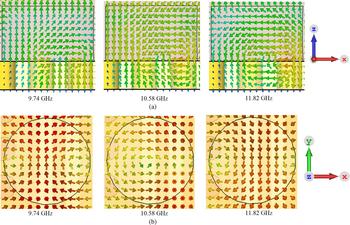
E- and H-field distribution at resonant frequencies (9.74, 10.58, and 11.82 GHz) is shown in Fig. 4. The cutting planes for E- and H-fields are XZ and XY planes, respectively. It is observed that in a cylindrical-shaped DRA, the direction of field distribution is changed by changing the frequency which verifies the presence of hybrid mode, i.e. EH11δ mode.
Field distribution in cylindrical DR: (a) electric field, (b) magnetic field.

The comparison of the simulated radiation efficiency for the proposed DRA with horn and without horn is shown in Fig. 5. It is observed that the radiation efficiency is nearly similar and more than 90% in most of the operating band for both DRAs, i.e. DRA with and without focusing horn. In general case, with addition/integration of the horn to DRA, the antenna system is expected to be lossy in nature which will always result in the reduction of the radiation efficiency. In the case of the proposed DRA, the radiation efficiency is not altered due to proper optimization of frequency-independent horn and simultaneously enhancing the gain as well as directivity. This aspect in itself is an important achievement. The values of simulated radiation efficiencies are 91, 92, and 95% at resonant frequencies 9.75, 10.58, and 11.82 GHz, respectively. Alike, polar radiation plot of total gain at their resonating frequencies (9.74, 10.58, and 11.82 GHz) are plotted in Fig. 6. This plot also distinguishes the DRA with horn to DRA without horn. The enchantment of gain is clearly justified in the main radiation (lobe) direction for horn-mounted DRA condition. The deviation in main radiating lobe from boresight direction also verifies the presence of hybrid mode. First analyzed at φ = 0°: for DRA without horn, the main lobe direction is at an angle of 27°, −41°, and −31° with the angular width (3 dB) of 123.4°, 146.5°, and 117.4° at resonating frequencies 9.74, 10.58, and 11.82 GHz, respectively. Likewise, in case of DRA with horn, the main lobe direction is at an angle of 5°, −21°, and −6° with the angular width (3 dB) of 51.5°, 50.3°, and 60.5° at resonating frequencies 9.74, 10.58, and 11.82 GHz, respectively. Then analyzed at φ = 90°: for DRA without horn, the main lobe direction is at an angle of 1°, 31°, and 14° with the angular width (3 dB) of 83.9°, 127.2°, and 108.2° at resonating frequencies 9.74, 10.58, and 11.82 GHz, respectively. Correspondingly, in case of DRA with horn, the main lobe direction is at an angle of 0°, 1°, and 14° with the angular width (3 dB) of 62.3°, 95.6°, and 61.7° at resonating frequencies 9.74, 10.58, and 11.82 GHz, respectively.
Efficiency plot of proposed DRA with and without horn.

Gain radiation pattern of proposed DRA with and without horn at 9.74, 10.58, and 11.82 GHz: (a) φ = 0°, (b) φ = 90°.

To authenticate the outcomes, a prototype of DRA is developed and verified experimentally. The photograph of fabricated DRA is shown in Fig. 7. Proposed antenna is very light in weight and compact in size, as horn is made up of copper-taped plastic material having the density of ~1.3 g/cm3, which is much lesser than other conducting materials like copper having density ~8.9 g/cm3. This justifies the light weight of antenna. The volume of the horn is 2.14 cm3, while the overall volume of the antenna is 4.44 cm3 only. The reflection coefficient is measured using the E8364B PNA Network Analyzer, while the radiation characteristics are measured using an antenna measurement setup. Measured and simulated variation of the reflection coefficient is illustrated in Fig. 8. Feed element, i.e. SIW resonator without horn and DR, shows the non-resonating characteristics in X-band having an average reflection coefficient of −0.2 dB only. The measured impedance bandwidths of the proposed DRA are 65 MHz for 9.78 GHz resonance, 180 MHz for 10.58 GHz resonance, and 240 MHz for 11.84 GHz resonance. The resonant frequency and impedance bandwidth of the proposed DRA with and without horn are nearly identical. It is observed that DRA with and without focusing horn shows the purely non-resonating characteristics outside the operating frequency bands as displayed in Fig. 8. Since the proposed DRA is multiband/triple-band with narrow bandwidth, therefore the stopband behavior of the proposed antenna system is not analyzed separately for other cases in the outer range of frequencies and found it to be less informative.
Fabricated model of proposed SIW feed DRA mounted with horn.

Simulated and measured reflection coefficient of proposed feed and DRA with as well as without horn.

The variations of peak gain versus frequency for proposed DRA with and without horn are shown in Fig. 9. The peak gain without horn is 6 dBi at 9.76 GHz, 6.5 dBi at 10.54 GHz, and 7 dBi at 11.8 GHz, while with horn is 8.9 dBi at 9.74 GHz, 8.4 dBi at 10.58 GHz, and 9.7 dBi at 11.82 GHz. It is clearly observed that mounted horn enhances the average gain by ~3 dB in the first band, ~1.7 dB in the second band, and ~2.5 dB in the third operating region. Thus, enhancement of the gain in all three operating bands simultaneously verifies the great feature of the proposed antenna. Generally, it is not possible by any other gain enhancement techniques, e.g. EBG and metamaterial structures as these structures are frequency-dependent or resonating characteristics. The achieved gain flatness is very impressive for first and third operating bands, i.e. ±0.05 and ±0.13 dB, respectively, while ±1.58 dB for the second band. The comparison of the antenna outcomes with horn and without horn is presented in Table 2. The simulated impedance bandwidths for DRA with horn are 70, 175, and 240 MHz at resonant frequencies 9.74, 10.58, and 11.82 GHz, respectively. Similarly, impedance bandwidths for DRA without horn are 60, 170, and 240 MHz at resonant frequencies 9.76, 10.54, and 11.8 GHz, respectively.
Peak gain of proposed DRA with and without horn.

Comparison of results for with horn and without horn DRA

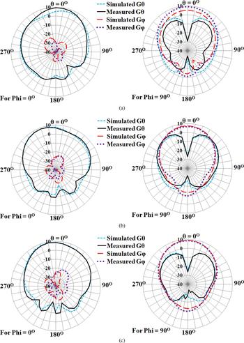
The simulated and measured radiation patterns of the proposed DRA at resonant frequencies are shown in Fig. 10. It is observed that the difference between gain θ (Gθ) and gain φ (Gφ) level is more than 25 dB for φ = 0° and this difference is lesser for φ = 90°. Thus, proposed DRA has linear polarization. Prototype antenna has an asymmetry structure, and due to that, radiation pattern is disproportionate for φ = 0° plane and has minor tilt from the boresight. The summary of the simulated and experimentally achieved results for proposed DRA is presented in Table 3, which is good in the agreement. Table 4 validates the achievement of the proposed DRA by comparing with the best cases of other published references. Proposed DRA provides gain enhancement with compact size compared with others.
Simulated and measured radiation pattern for proposed DRA: (a) 9.78 GHz, (b) 10.58 GHz, (c) 11.84 GHz.

Comparison between simulated and measured outcomes

Sim., simulated; Meas., measured; fr, resonant frequency; BW, impedance bandwidth for |S 11| <−10 dB.
Comparison of proposed DRA with other published DRA mounted with horn.

Conclusion
A light-weight horn-mounted DRA excited by SIW resonator feed is successfully implemented. This simple and interesting structure of the proposed antenna enhances the average gain by ~3 dB in the first operating band, ~1.7 dB in the second operational band, and ~2.5 dB in the third operating region. The measured peak gain of horn-mounted DRA is 9.3 dBi at 11.84 GHz within all triple band of operation. The important achievement of the novel structure is to enhance the gain of all three operating bands simultaneously without affecting the radiation efficiency. Enhancing the gain of the multiband antenna by EBG, metamaterial, etc., is not possible as they are frequency-selective in nature. This is an incredible feature of the proposed antenna. Proposed DRA offers triple band characteristics with dignified bandwidths that are 65 MHz at 9.78 GHz, 180 MHz at 10.58 GHz, and 240 MHz at 11.84 GHz for |S 11| <−10 dB. As antenna offers high gain and multi-band with narrow bandwidth, this makes it highly selective and suitable for secure military communication beyond LOS. Proposed antenna can also be used as a highly selective antenna for multiband utility such as medical treatment, defense applications, and X-band applications. To the best of our knowledge, such simple geometry of compact antenna for triple band applications has not been explored so far.
Author ORCIDs
Jitendra Kumar, 0000-0002-8480-6276
Acknowledgement
The authors would like to acknowledge Amitesh Kumar, Scientist, Society for Applied Microwave Electronics Engineering and Research (SAMEER), Kolkata, India for providing measurement support.
 Pramod Kumar received his B.Tech. degree from Sant Longwal Institute of Engineering and Technology, Longwal, Punjab, India in 2004 and M.Tech. degree in Microwave Electronics from University of Delhi, New Delhi, India, in year 2008. Currently, he is working toward his Ph.D. degree in Electronics Engineering from Indian Institute of Technology (formerly Indian School of Mines), Dhanbad, India. He is also working as an Assistant Professor with the Department of Electronics & Communication Engineering, Inderprastha Engineering College (IPEC), Ghaziabad, Uttar Pradesh, India. He is a life member of the Institution of Electronics and Telecommunication Engineers (IETE), New Delhi, India. His recent research includes design and characterization of dielectric resonator antenna.
 Jitendra Kumar is currently working as a Post-Doctoral Fellow (PDF) in Microwave Plasma Group, Institute for Plasma Research, Gandhinagar, Gujarat, India. He received the Associate degree in Electronics and Telecommunication from The Institution of Electronics and Telecommunication Engineers (IETE), New Delhi, India, in 2008 and M.Tech. degree in Microwave Electronics from the University of Delhi, New Delhi, India, in 2010. He received his Ph.D. degree from the Department of Electrical and Electronics Engineering, Birla Institute of Technology and Science, Pilani, (BITS-Pilani) Rajasthan, India in 2016. He is also the life member of IETE. His research interests include antenna design and microwave engineering.
 Shailendra Singh received his M.Tech. degree in Microwave Electronics from the University of Delhi South Campus, New Delhi, India, in year 2013 and B.Tech. degree from Galgotia College of Engineering and Technology, Gr. Noida, India. He is currently working as a Deputy Engineer in Bharat Electronics Limited Bangalore, India. His research interest includes antenna design, microwave wireless communication, digital board testing, and real time system integration and testing. He has also worked in the Institute for Plasma Research and CEERI-Pilani, India. He has published more than 15 research papers in international and national journal and conference proceeding papers.
 Utkarsh has studied from the Department of Electronics and Communication Engineering, Inderprastha Engineering College (IPEC), Ghaziabad, Uttar Pradesh, India. He has published several research papers in reputed national and international journals as well as conferences. His research interests include electromagnetic field theory, dielectric resonator antenna (DRA) design, and development for broadband and ultra-wide band applications using biodegradable materials by utilizing additive manufacturing process.
 Santanu Dwari was born in Howrah, West Bengal, India. He received his B.Tech. and M.Tech. degree in Radio Physics and Electronics from the University of Calcutta, Kolkata, West Bengal, India in the year of 2000 and 2002, respectively, and Ph.D. degree from Indian Institute of Technology, Kharagpur, West Bengal, India in the year of 2009. He joined Indian Institute of Technology (Indian School of Mines), Dhanbad, Jharkhand, India in 2008 where he is currently an Assistant Professor in the Department of Electronics Engineering. He has published several research papers in referred international journals. His research interest includes antennas, RF planar circuits, computational electromagnetics.