Introduction
Antenna serves an important part of the communication system, and its performance directly affects the quality and reliability of communication. Circularly polarized (CP) antennas have strong anti-interference ability and good anti-multipath fading performance, providing stable and reliable communication services in complex communication environments [Reference Bertrand, Ettorre, Valerio, Albani and Casaletti1–Reference Kun, Li, Zhao, Han, Han and Liu3].
At present, there are many methods to achieve circular polarization, which are mainly divided into single-point feeding [Reference Birwal, Patel and Singh4, Reference Han, Zheng, Su, Yuan and Zhang5] and multi-point feeding [Reference Wei, He, Zeng, Fei and Liu6, Reference Li, Xue, Li, Chung and Huang7]. Specifically, in order to improve the axial ratio bandwidth (ARBW), several methods have been proposed, such as the use of multilayer structure [Reference Cheng, Zhou, Yang, Wu and Huang8, Reference Muntoni, Casula, Traversari and Montisci9], metasurface antenna with periodic structure [Reference Shi, Chai, Chen, Li, Zhang and Tang10, Reference Li, Wu, Liang and Su11], and the use of sequential rotation phase (SRP) feeding network [Reference Wu, Yang, Gu, Xue and Che12, Reference Chen, Zhang, He, Fan, Zhu, Zhang, Li and Zhao13]. The multilayer structure improves the bandwidth by introducing additional resonant properties. In [Reference Cheng, Huang, Huang and Yang14], a double-layer radiating patch is proposed, where the lower patch consists of a square outer loop and a three-quarter ring inner loop, and the upper layer is used for impedance matching, achieving a −10-dB impedance bandwidth (IBW) of 15.2% and a 3-dB ARBW of 8.2%, as well as a peak gain of 7 dBi. Metasurface antenna achieves bandwidth expansion by changing the surface impedance distribution by adjusting the size, shape, and arrangement of the periodic elements. In [Reference Yousfi, Lamkaddem, Abdalmalak and Segovia-Vargas15], a low-profile coplanar waveguide metasurface antenna is proposed, which is excited by a coplanar waveguide (CPW) feeding with a certain rotation angle at the bottom, and achieves a −10-dB IBW of 25%, a 3-dB ARBW of 19%, and a peak gain of 8 dBi. Compared with the previous two methods, the CP array antenna implemented by SRP technology can improve CP characteristics by introducing phase differences between different subarrays [Reference Ma, Ma and Zhang16], it is easier to achieve higher gain and wider bandwidth. In [Reference Liu, Zhang and Zhao17], a wideband CP antenna array is proposed based on SRP using crossed-dipole elements, achieving a −10-dB IBW of 44%, a 3-dB ARBW of 34.6%, a peak gain of 11 dBic, and its overall size is  $1.89\lambda_0\times1.65\lambda_0\times0.11\lambda_0$. In [Reference Bai, Wang and Zou18], a substrate integrated waveguide cavity antenna array based on metasurface is achieved, with a −10-dB IBW of 38%, a 3-dB ARBW of 24.9%, a peak gain of 12.1 dBic, and an overall size of
 $2.18\lambda_0\times2.18\lambda_0\times0.06\lambda_0$. However, array antennas based on SRP generally suffer from the issues of large design size and low gain, which is not suitable for the current development trend of communication systems. Additionally, for space-limited scenarios, such as satellite communications, achieving high gain and high polarization purity (low cross-polarization) remains a challenge.
To solve the above issues, a compact wideband and high-gain  $2\times2$ CP array antenna is achieved using SRP feeding network based on substrate integrated gap waveguide (SIGW). SIGW is a novel waveguide structure that has been proposed in recent years [Reference Zhang, Zhang and Kishk19, Reference Attia, Sorkherizi and Kishk20]. It merits advantages such as low radiation loss and easy integration, making it widely used in the design of various microwave devices, such as filters [Reference Lin, Shen, Wang and Luo21] and antennas [Reference Wang, Shen, Lin, Luo, Wang, Chen, Gao and Zhang22]. Compared to traditional SRP feeding network, the SIGW-SRP feeding network structure proposed in this paper is simple, easy to fabricate, and enables to achieve compact array antenna. The final implemented wideband high-gain CP array antenna has low cross polarization and low back radiation, and achieves −10-dB IBW of 34.6%, 3-dB ARBW of 21.2%, and the peak gain of 16 dBic. The overall size is only
 $1.5\lambda_0\times1.5\lambda_0\times0.11\lambda_0$.
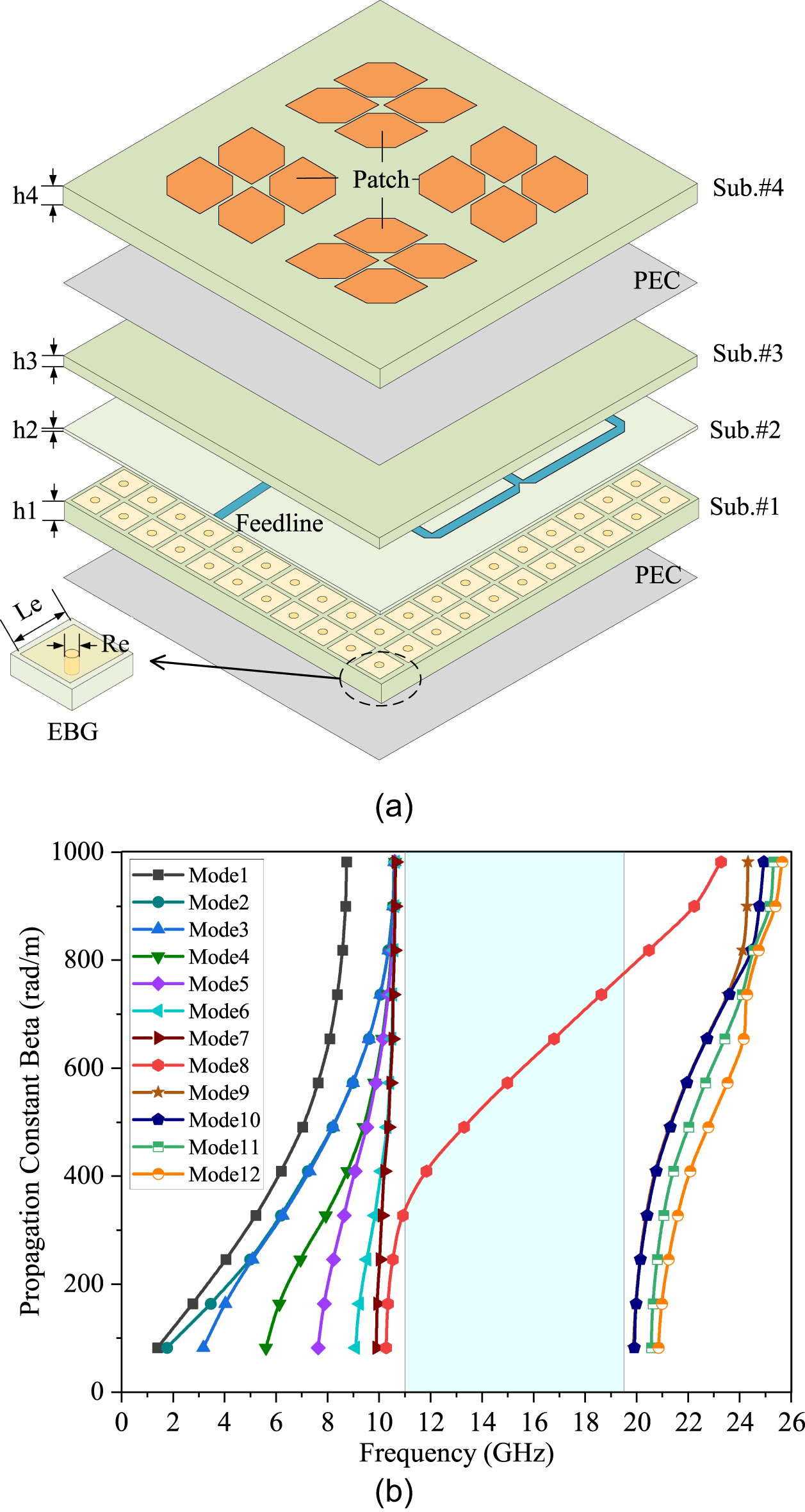
(a) Structure of the array antenna. (b) SIGW dispersion curve. The relevant parameters are: h1 = 0.813, h2 = 0.203, h3 = 0.508, h4 = 0.813, Le = 2.4, Re = 0.3 (units: mm).

Section 2 presents the structure and operating mechanism of the proposed array antenna, including the antenna element and the SIGW-SRP feeding network. Section 3 provides the measured results of the proposed array antenna and some brief discussions. Finally, Section 4 presents the conclusions.
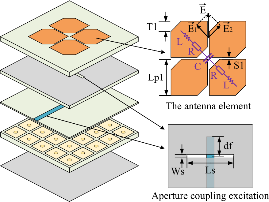
The overall structure of the antenna element. The relevant parameters of the proposed antenna element are: T1 = 1.2, Lp1 = 4.2, S1 = 0.2, df = 1.8, Ls = 6, Ws = 0.5 (units: mm).

Feed network structure design based on SIGW-SRP
Array antenna structure design
As shown in Fig. 1(a), the proposed array antenna is composed of four layers of dielectric substrates, and all substrate materials are Rogers 4003C ( ${\varepsilon _r} = 3.55$ and
 $\tan \delta=0.0027$). Sub.#1 to Sub.#3 form SIGW structure (Sub.#1 consists of periodic Electromagnetic Band Gap (EBG) cells, Sub.#2 serves as an isolation layer, and the upper surface of Sub.#3 is printed perfect electric conductor (PEC) as GND). Furthermore, the dispersion curve of SIGW is shown in Fig. 1(b). It can be observed that the electromagnetic bandgap range is 11–19.5 GHz, and only one Quasi-Transverse Electromagnetic Mode (Quasi-TEM) wave can propagate within the bandgap, which means minimum distortion during signal transmission. In addition, the array antenna consists of four
 $2\times2$ corner-cutting patch elements placed orthogonally (achieving stable and symmetry radiation patterns).
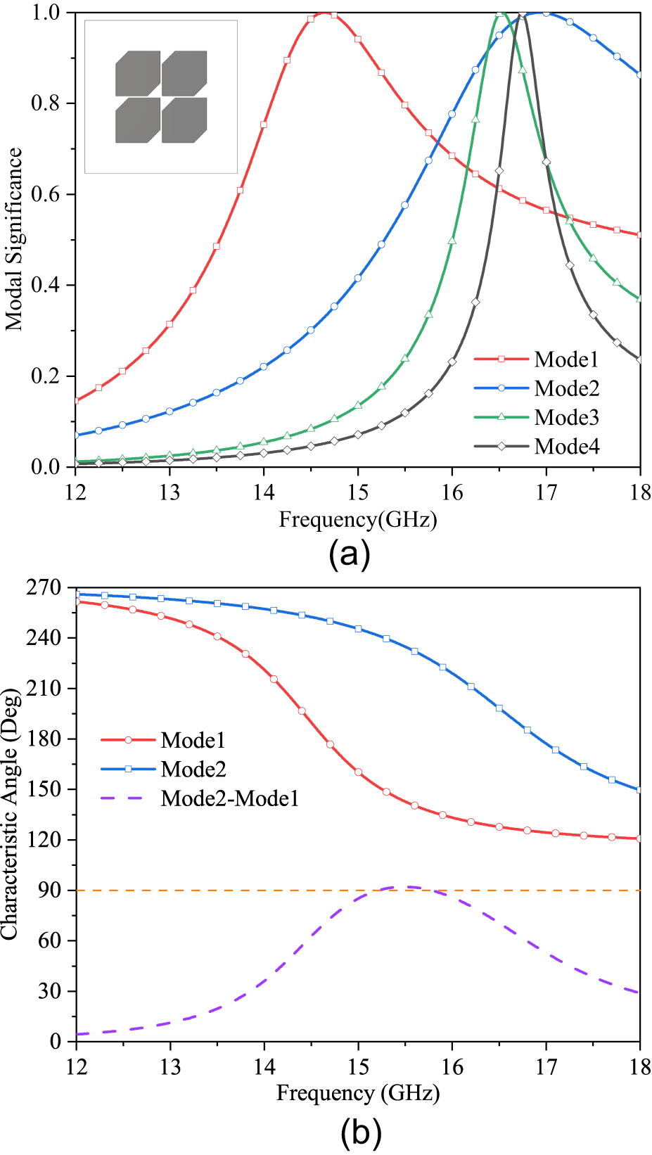
(a) MS of the first two modes. (b) CA of the first two modes.

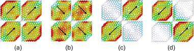
Surface current. (a) Mode1. (b) Mode2. (c) Mode3. (d) Mode4.

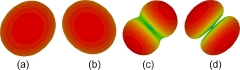
Far field. (a) Mode1. (b) Mode2. (c) Mode3. (d) Mode4.

In SIGW, since the electric field is almost confined to the region between the inner microstripline (MSL) and the upper PEC [Reference Bayat-Makou and Kishk23], then when all dielectric substrates of SIGW have the same material, SIGW can be approximated as the MSL with the relative permittivity ɛr filled by the surrounding dielectric. In this way, the characteristic impedance of SIGW can be approximately calculated using the characteristic impedance of MSL [Reference Ma, Ma and Zhang16]:
 \begin{equation}
Z_{\mathrm{SIGW}}\cong\sqrt{\frac{\varepsilon_e}{\varepsilon_r}}Z_{\mathrm{MSL}}
\end{equation}
where  $Z_\mathrm{MSL}$ is the characteristic impedance of MSL,
 $Z_\mathrm{SIGW}$ is the characteristic impedance of SIGW, and ɛe is the effective permittivity. The use of SIGW benefits the suppression of cross polarization and back lobe radiation, and contributes to improve the forward radiation of the array antenna [Reference Wang, Shen, Lin, Luo, Wang, Chen, Gao and Zhang22].
Antenna element design and analysis
The antenna element structure is shown in Fig. 2, and the CP radiation performance can be explained by the equivalent circuit. The electric field  $\vec E$ generated by the antenna element is decomposed into two orthogonal components
 $\vec E_1$ and
 $\vec E_2$. The equivalent impedances on
 $\vec E_1$ and
 $\vec E_2$ directions are not equal because of the perturbation caused by the exist of the corner-cutting on the antenna element [Reference Han, Shen, Cao, Gao, Wei, Zhao, Li and Zhang24]:
 \begin{equation}
{Z_i} = {R_i} + j{X_i} = 2{R_i} + j\omega (2{{\rm{L}}_i}) + \frac{1}{{{{j}}\omega {{{C}}_i}}}
\end{equation}
where Ri is the resistance of the patch, Li is the inductance generated from the patch to GND, and Ci is the capacitance due to the gap between diagonal patches  $(i = 1,2)$. When
 $X_i=0$, the antenna resonates and the resonant frequency can be obtained, where
 $X_i=0$ is the reactance. Since the corner-cutting increases the gap of the diagonal patches, it will change the impedance value. When the size of T1 is set appropriately, the circular polarization condition can be satisfied, and the relationship between the two electric field components is:
 \begin{equation}
\left| {{{\vec E}_1}} \right| = \left| {{{\vec E}_2}} \right|,{\rm{ }}\angle {\vec E_2} - \angle {\vec E_1} = 90^\circ.
\end{equation}
When the operating wavelength is given, a wide circular polarization with good axial ratio can be achieved by selecting appropriate antenna dimensions and the relative permittivity of the substrate. For a single corner-cutting patch, the calculation formula for the size of the corner-cutting is as follows:
 \begin{equation}
\left| {\frac{{\Delta S}}{S}} \right| = \frac{1}{2{Q_0}}
\end{equation}
 \begin{equation}
S=(Lp1)^2
\end{equation}
 \begin{equation}
\Delta S = \frac{1}{2} (T1)^2
\end{equation}
where  $\Delta S$ represents the area of the corner-cutting, S represents the area of the patch, and Q 0 is the total quality factor of the antenna, which can be calculated using the following formula [Reference Wang, Fang, Wang and Liu25]:
 \begin{equation}
\frac{1}{Q_0} =\frac{1}{Q_r} +\frac{1}{Q_d} +\frac{1}{Q_c} +\frac{1}{Q_{sw}}
\end{equation}
 \begin{equation}
Q_r=\frac{\varepsilon_r ab}{60\lambda_0h\delta_{0m}\delta_{0n}G_r}
\end{equation}
 \begin{equation}
{Q_d} = \frac{1}{{\tan \delta }}
\end{equation}
 \begin{equation}
Q_c=h\sqrt{u_0\pi f_r\sigma}=\pi h\sqrt{120 \sigma/\lambda_0}
\end{equation}
 \begin{equation}
Q_{sw}=\frac{1}{3.4\sqrt{\varepsilon_{r}-1}\frac{h}{\lambda_{0}}}Q_{r}
\end{equation}
where Qr, Qd, Qc, and Qsw represent the quality factors of radiation, medium, dielectric loss, and surface wave, respectively. a and b represent the length and width of the antenna, respectively. σ represents the electrical conductivity of the patch metal.  $\mathrm{tan}\delta $ represents the tangent of the dielectric loss. µ 0 is the magnetic permeability of vacuum.
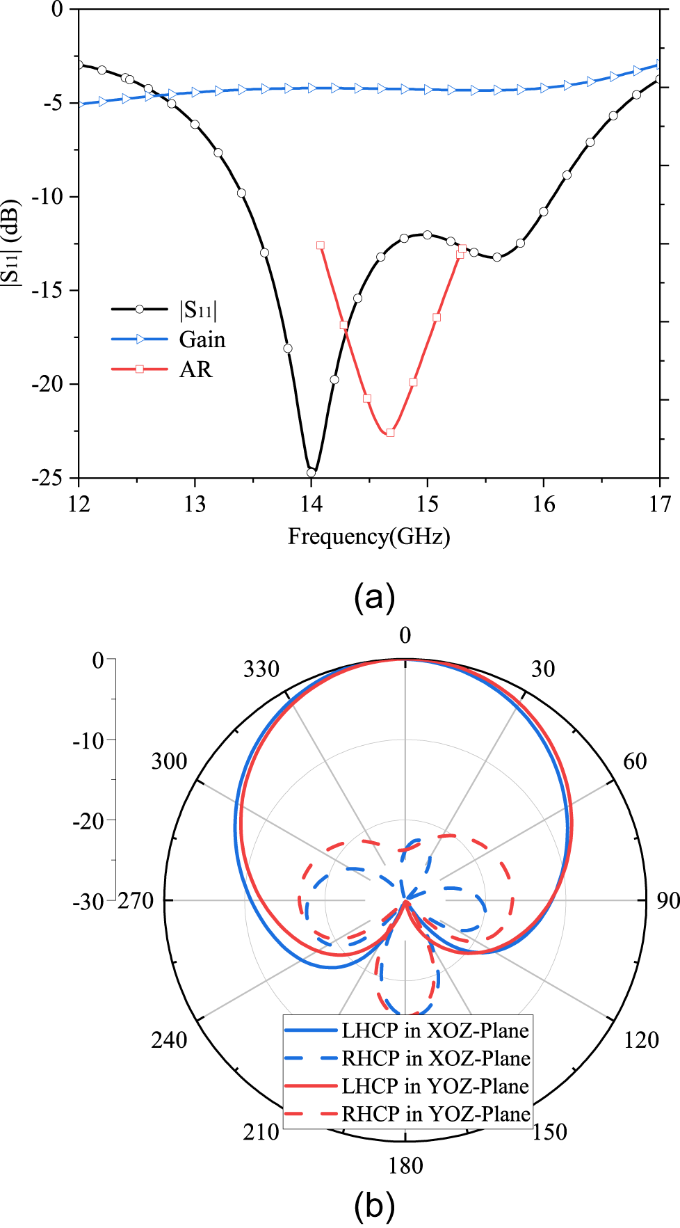
The simulated results of Ant1. (a)  $\lvert S_{11} \rvert$, gain, and AR. (b) Radiation pattern at 14.7 GHz.

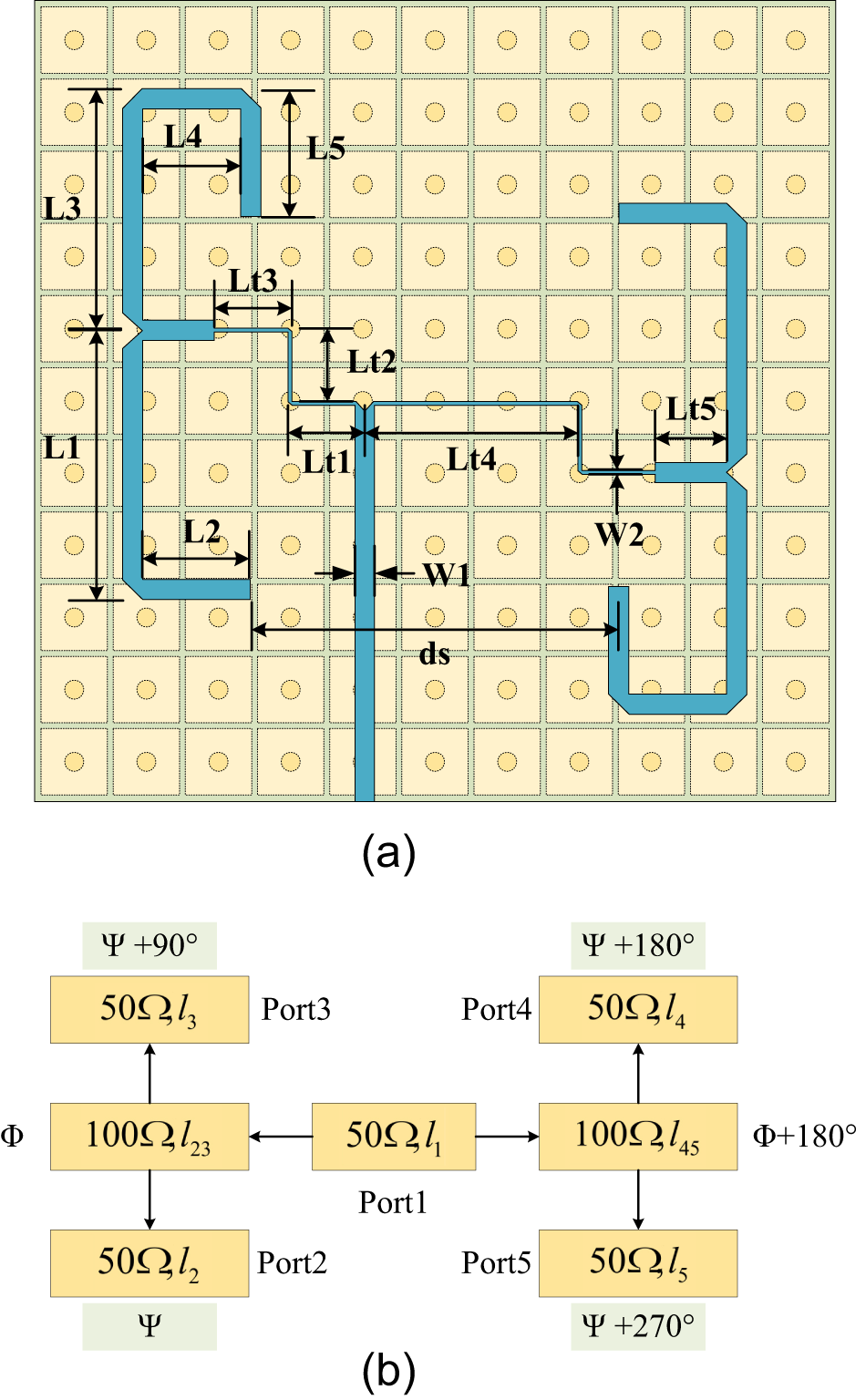
(a) SIGW-SRP structure. (b) SRP equivalent circuit. The relevant parameters of SRP feeding network are: W1 = 0.8, Lt1 = 3, Lt2 = 2.85, Lt3 = 3, Lt4 = 8.55, Lt5 = 2.8, L1 = 10.5, L2 = 5, L3 = 9.5, L4 = 5.4, L5 = 5, ds = 14.6 (units: mm).

If  $G_{r}\approx2G_{s}\approx\left(\mathrm{a}/\lambda_{0}\right)^{2}/45$, then
 $Q_{r}\approx\frac{3\varepsilon_{r} b/a}{8(\mathrm{h}/\lambda_{0})}$. According to the above method, the corner-cutting size
 $T1\approx1.2\;$mm can be preliminarily determined.
In order to provide a clear physical mechanism, characteristic mode theory is applied to analyze CP characteristics of the antenna element. It provides several important characteristic parameters: eigenvalue (λ), modal significance (MS), and characteristic angle (CA). The relevant calculation formulas are as follows [Reference Li, Wu, Liang and Su26]:
 \begin{equation}
\mathrm{MS} = \left| {\frac{1}{{1 + j{\lambda _n}}}} \right|
\end{equation}
 \begin{equation}
\mathrm{CA} = {180^ \circ } - {\tan ^{- 1}}{\lambda _n}
\end{equation}
where λn is the eigenvalue of Mode n. MS can intuitively show the possible characteristic patterns in the conductor structure. It indicates the contribution of each characteristic mode to the total field. When MS approaches 1, the mode is more likely to resonate easily. When MS approaches 0, the mode is less likely to resonate. Additionally, when MS  $\ge 0.707$, it is referred to as a significant mode, indicating that the mode is more easily excited. CA is the phase lag between the real characteristic current on the conductor surface and the tangential electric field. When the phase lag is 180∘, the corresponding mode is referred to as the most efficient radiating mode [Reference Garbacz27]. For CP radiation, it is necessary to excite at least two characteristic modes simultaneously. These modes should have λ equal to 0, equal MS values that are all greater than 0.707, and the phase difference between their CA close to 90∘ [Reference Chen and Wang28].
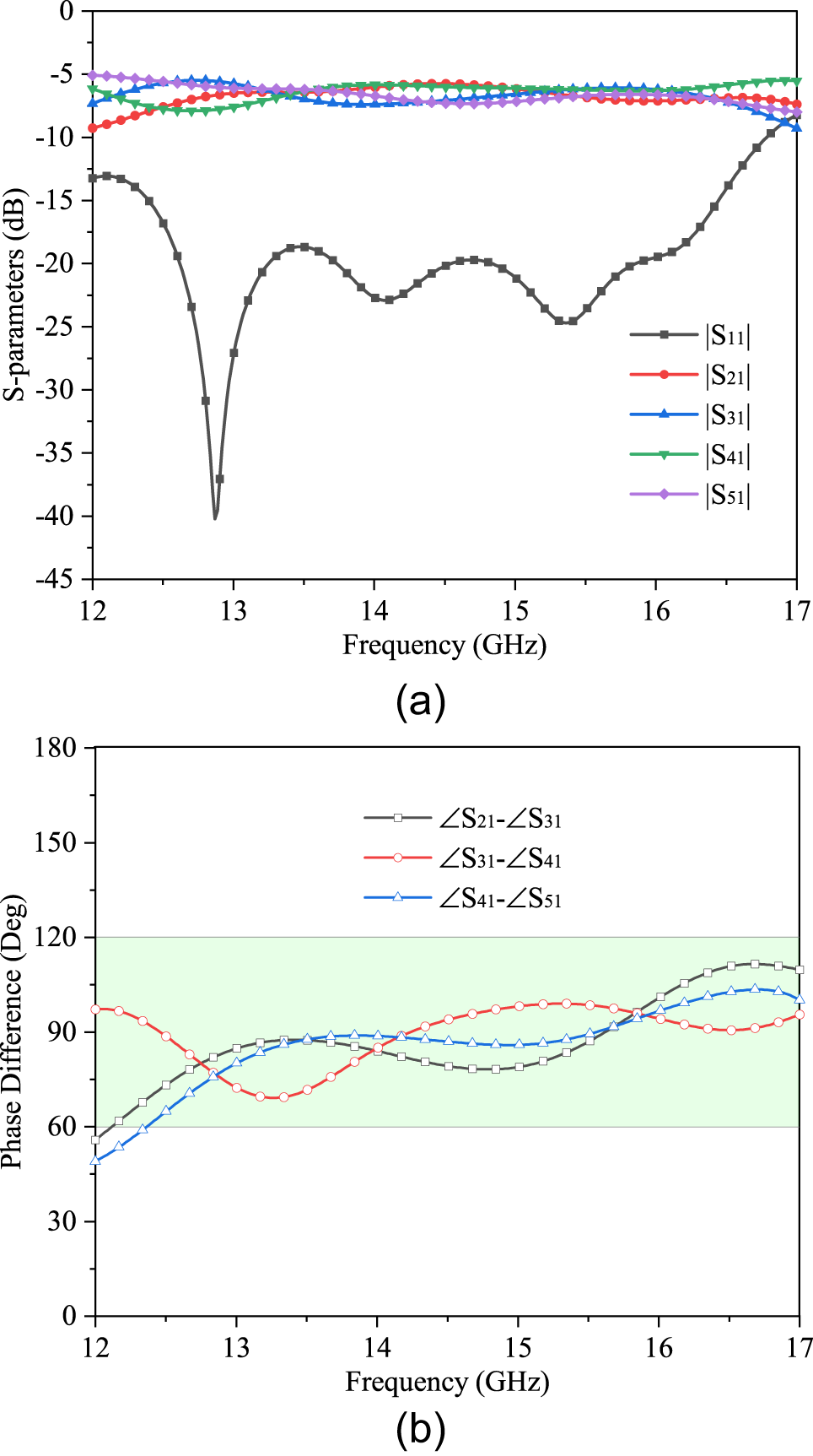
Simulated results of each port of SIGW-SRP. (a) S-parameter curves. (b) The phase difference curves.

Current distribution of the array antenna at 15 GHz.

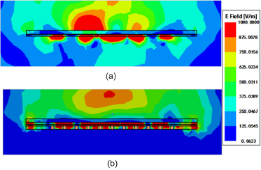
Electric field distribution of the array antenna at 15 GHz. (a) Without SIGW. (b) With SIGW.

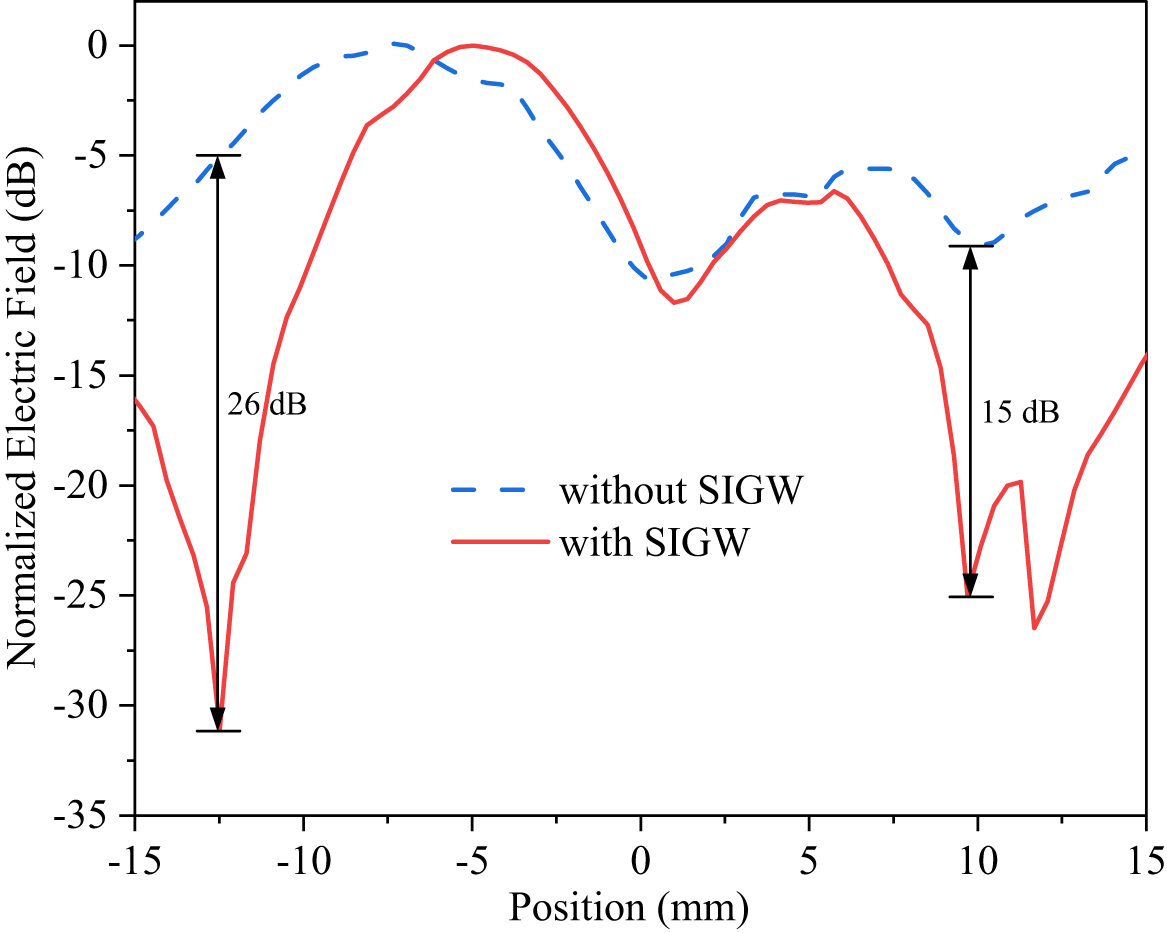
Effect of SIGW on transverse electric field distributions.

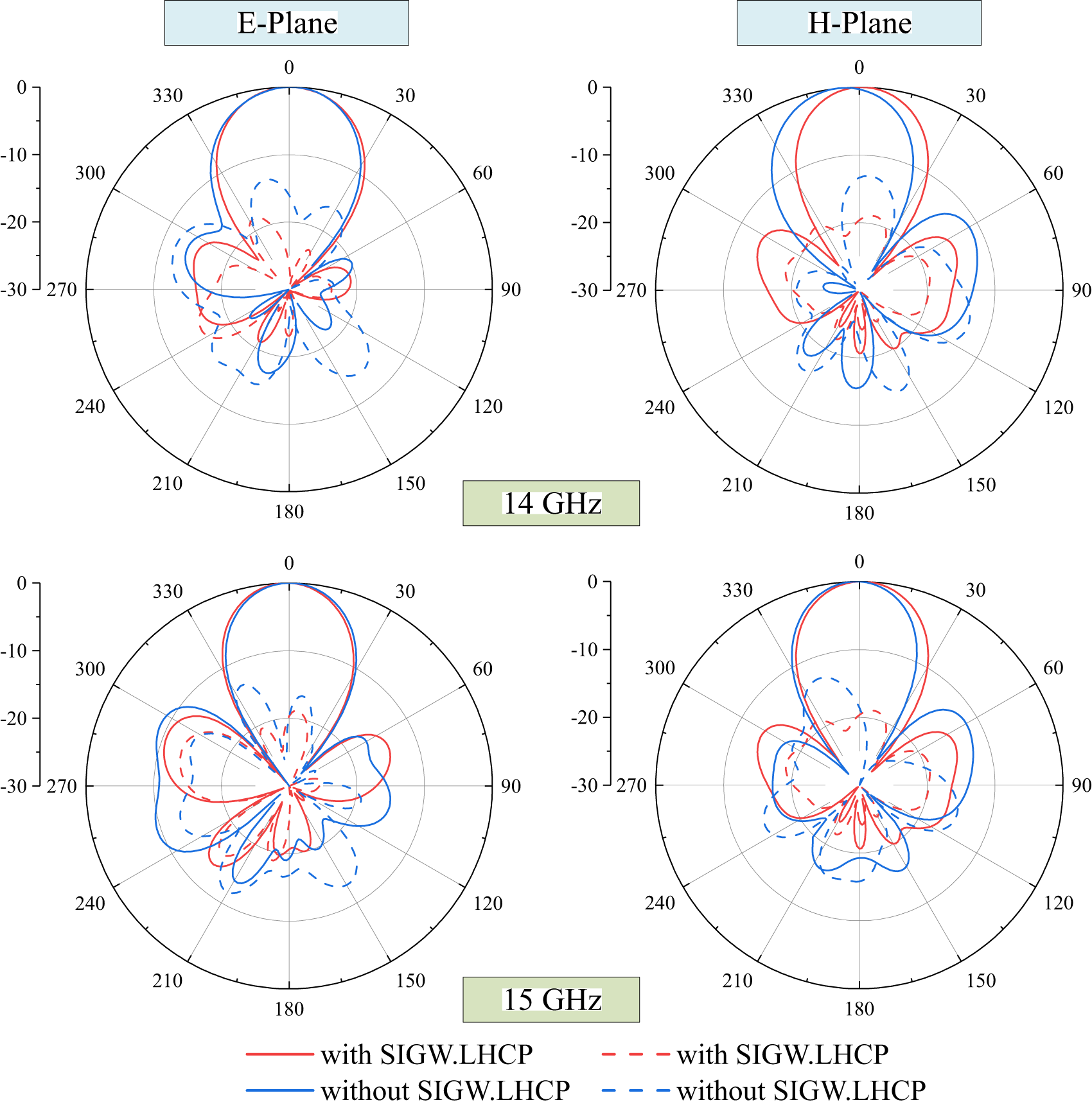
Comparison of simulated radiation patterns with and without SIGW at 14 GHz and 15 GHz.

The antenna element without excitation is analyzed using CST software. MS of the first four modes are shown in Fig. 3(a). Mode1 to Mode4 are resonant around at 14.6 GHz, 16.9 GHz, 16.5 GHz, and 16.7 GHz, respectively. Moreover, Mode1 and Mode2 have equal MS at around 15.8 GHz and a phase difference of about 90∘ in Fig. 3(b). Therefore, the antenna element can produce CP radiation near 15.8 GHz.
To further characterize the radiation performance of the antenna element, the current distributions and radiation patterns of the first four modes at their respective resonance frequencies are shown in Figs. 4 and 5, respectively. Mode1 and Mode2 both exhibit co-directional currents and have orthogonal distributions, indicating that they are a pair of degenerate modes. It is worth mentioning that if the characteristic modes excite counter-directional currents, it can result in radiation cancellation, leading to no radiation energy in the radiation direction. This is evident in the cases of Mode3 and Mode4.
Next, the antenna element is simulated using ANSYS HFSS. From Fig. 6(a), it can be observed that IBW ranges from 13.41 to 16.08 GHz, ARBW ranges from 14.37 to 16.95 GHz, and the gain is greater than 9 dBic. Figure 6(b) shows the radiation pattern at 14.7 GHz in the XOY and YOZ planes, which has greater the left-hand circular polarization (LHCP) gain.
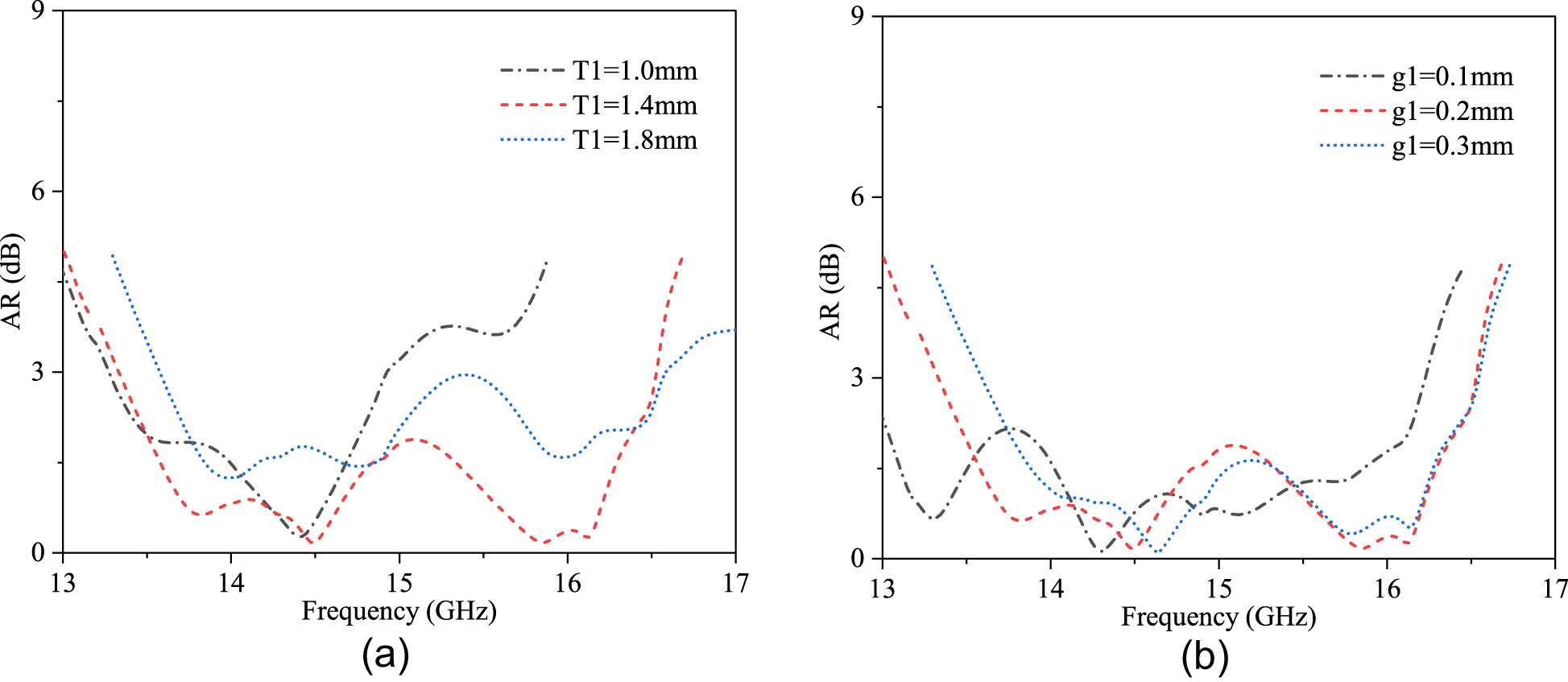
AR under different parameters. (a) T1. (b) G1.

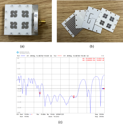
(a) Overall prototype photo of the proposed array antenna. (b) Disassembly prototype photo of the proposed array antenna. (c) The VNA screenshots of S-parameters outcomes.

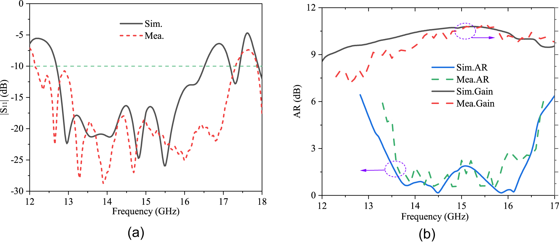
The simulated and measured results of Array1. (a)  $\lvert S_{11} \rvert$ and gain. (b) AR.

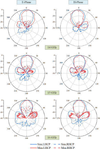
The simulated and measured radiation patterns at 14 GHz, 15 GHz, and 16 GHz.

It is worth noting that CP resonance point obtained from CMA is at 15.8 GHz, while the actual simulated CP resonance point is at 14.7 GHz. Due to the aperture coupling feeding used, the resonance generated by the slot can introduce some interference to the antenna’s own resonance, thereby causing a deviation in CP resonance point.
Feeding network structure design based SIGW
The feeding network structure based on SIGW-SRP is shown in Fig. 7(a). The essence of SRP is to optimize the radiation performance of an antenna by utilizing the vector addition of electromagnetic waves and compensating for phase variations by changing the antenna position. According to characteristic mode theory, it can be determined that achieving CP characteristics requires a phase difference of 90∘. Therefore, by sequentially delaying the output energy of each port of the feeding network by 90∘, the array antenna can exhibit different CP resonance characteristics to expand bandwidth [Reference Bai, Wang and Zou18].
To demonstrate the working mechanism of the feeding network, the equivalent circuit of SRP is shown in Fig. 7(b). Equal power distribution among the ports of the feeding network is achieved by varying the widths of the branches. Furthermore, the desired sequential rotation of phase by 90∘ for each port is achieved by adjusting the lengths of the branches. Due to equal power distribution is desired among the ports, the following can be obtained:
 \begin{equation}
{P_2} = {P_3} = {P_4} = {P_5} = \frac{{{P_1}}}{4}
\end{equation}
 \begin{equation}
{l_3} = {l_2} + {l_{\lambda /4}}
\end{equation}
 \begin{equation}
{l_5} = {l_4} + {l_{\lambda /4}}
\end{equation}
 \begin{equation}
{l_{45}} = {l_{23}} + {l_{\lambda /2}}
\end{equation}
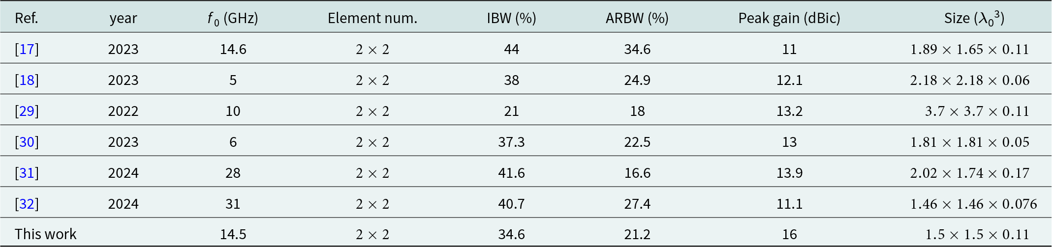
Comparison to the recently reported CP array antennas based on SRP.

where Pn represents the power at each port and ln represents the electrical length of each branch  $(n = 1,2, \ldots)$.
From Fig. 8(a), it can be observed that S-parameter curves of all ports in the SRP feeding network. Within the range of 12.5–16.5 GHz,  $\lvert S_{11} \rvert$ is consistently less than −15 dB, and
 $\lvert S_{21} \rvert$ to
 $\lvert S_{51} \rvert$ are all within the range of −6 ± 2 dB. Additionally, from the phase difference curves of adjacent ports in Fig. 8(b), it can be observed that within the range of 12.5–16.5 GHz, the phase difference between adjacent ports remains within
 $90^\circ \pm 30^\circ $. Since SIGW can achieve a wide and stable IBW, the SIGW-SRP feeding network achieves the wide bandwidth and stable phase difference curves [Reference Zhang, Zhang and Kishk19].
In summary, the design procedures of the proposed antenna are as follows:
(1) The SIGW structure is designed to operate in the Ku-band to reduce back radiation and surface wave leakage.
(2) The size of the antenna element corner-cutting is calculated by theoretical formula. Characteristic mode analysis method is used to guide the antenna element design, and the first two modes (a pair of degenerate modes) are selected as the operating modes to achieve wide IBW and generate CP waves.
(3) The SIGW-SRP feed network is designed with a phase difference of 90∘ between two adjacent ports. By utilizing spatial vector superposition, the axial bandwidth is further expanded, and the gain is improved.
(4) The antenna element and the SIGW-SRP feeding structure are designed in combination to finally form a
 $2\times2$ array antenna.

Verification and analysis
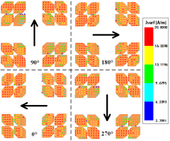
Figure 9 shows the current distribution of the proposed array antenna at 15 GHz, and the current flows in the clockwise direction at 0∘, 90∘, 180∘, and 270∘ phases, explaining the left-hand circular polarization (LHRP) operation mechanism.
To further illustrate the advantages of SIGW, the antenna with SIGW and the antenna without SIGW are simulated respectively. Figure 10 shows the electric field distribution observed on a reference plane. It can be seen that the antenna loaded with SIGW has almost no back radiation compared to the antenna without SIGW loading. Figure 11 shows the transverse electric field distribution on a reference line, where loading SIGW reduces the edge electric field by 26 dB and 15 dB on both sides, respectively, proving that loading SIGW can significantly suppress the transverse radiation. At the midpoint, both curves have a slight decrease because there is no radiating element in the center of the array antenna. The above simulation results show that loading SIGW can suppress the back radiation and transverse radiation, which is because SIGW can achieve in-phase reflection and suppress surface wave leakage at the high frequency band [Reference Wang, Shen, Lin, Luo, Wang, Chen, Gao and Zhang22]. Figure 12 shows the radiation pattern of the two antennas at 14 GHz and 15 GHz. It can be seen that the antenna loading SIGW has an average backlobe reduction of about 3.8 dB in the 180∘ direction and an average cross-polarization reduction of about 4.6 dB in the 0∘ direction, which proves the effect of SIGW to suppress the back radiation to improve directivity and suppress the cross polarization.
To improve the circular polarization performance, parameter analyses are conducted. As shown in Fig. 13, both the corner-cutting size of the antenna element and the spacing between the patches affect the circular polarization characteristics, with the corner-cutting size having a more significant impact.
To validate the performance of the proposed array antenna, a prototype is fabricated. The prototype photos and the vector network analyzer (VNA) screenshots are shown in Fig. 14. As seen from Fig. 15(a), the measured −10 dB IBW is from 12.2 to 17.3 GHz (34.6%), while the simulated one is from 12.4 to 16.4 GHz (27.8%). As seen from Fig. 15(b), the measured 3 dB ARBW ranges from 13.5 to 16.7 GHz (21.2%), while the simulated one ranges from 13.3 to 16.5 GHz (21.5%), and the measured peak gain is 16 dBic, while the simulated peak gain is 16.1 dBic. It is worth noting that due to factors such as processing accuracy, measuring, and the connecter, there are some deviations between the measured results and the simulated results.
Figure 16 shows the radiation patterns of the proposed array antenna at different frequencies. It can be observed that the proposed array antenna is LHCP with good symmetry. In addition, from the electric field distribution in Fig. 10, it can be well explained that the proposed array antenna can suppress the cross-polarization of about 17 dB at the 0∘ axial radiation direction due to the use of SIGW.
In order to further describe the performance of the proposed array antenna, some recently reported SRP array antennas are listed in Table 1. Compared with [Reference Liu, Zhang and Zhao17, Reference Bai, Wang and Zou18, Reference Pramono, Sumantyo, Ibrahim, Takahashi, Yoshimoto, Kashihara, Santosa, Gao and Ito30] and [Reference Ye, Li, Han and Dou32], although the proposed array antenna has a narrower bandwidth, it has higher gain. Overall, the proposed array antenna has obvious advantages in size and gain, which aligns with the trend toward miniaturization development.
Conclusion
A compact, wideband, and high-gain CP array antenna based on SIGW-SRP feeding network is proposed in this paper. Due to the antenna element can only achieve narrow bandwidth and low gain, a  $2\times2$ array antenna is achieved through the compensation phase of the SIGW-SRP feeding network, which can greatly expand the bandwidth and improve the gain. The measured results show that the −10-dB IBW of the antenna is from 12.2 to 17.3 GHz (34.6%), the 3-dB ARBW is from 13.5 to 16.7 GHz (21.2%), and the peak gain reaches 16 dBic. Simulation results show that loading SIGW can reduce the back radiation and transverse radiation. The proposed antenna achieves broadband, high gain, and compact size, making it suitable for space-limited communication applications.
Acknowledgements
This research is supported by the National key research and development program of China (No2021YFB2900401) and State Key Laboratory of Matamaterial Electromagnetic Modulation Technology (Research on Low RCS Reconfigurable Antenna based on electromagnetic metamaterials).
Competing interests
The author(s) declare none.

Pengpeng Chen received the B.S. degree in Measurement and Control Technology and Instrument from Wuhan University (WHU) in 2021. He is currently pursuing the master degree at school of electronics and communication engineering, Sun Yat-sen University (SYSU). His current research is wideband circularly polarized metamaterial antenna.

Wenjian Wang received the M.S. degree in Environmental Chemistry from Fuzhou University, Fuzhou, Fujian, China, in 2010. Since then, he has been joined Kuang-Chi Institute of Advanced Technology China, where he was a researcher on electronic engineering. He is currently pursuing the Ph.D. degree with the College of Electronics and Communication Engineering, Sun Yat-sen University, Shenzhen, China. His current research interests include metamaterials, high-gain antenna arrays, radar, RCS reduction, ultrawideband technology, and wave propagation in complex media.

Lihui Wang received the M.S. degree in communication and information system from Yunnan University, Kunming, China, in 2022, and he is currently pursuing the Ph.D. degree at the school of electronics and communication engineering, Sun Yat-sen University, Shenzhen, China. His current research interests include phased array antenna technology and millimeter antenna for satellite communications.

Qiuhua Lin received the B.S. degree, in 2018. And he received the M.E. degree from Yunnan University, Kunming, China, in 2022. He is currently pursuing the Ph.D. degree at Sun Yat-sen University, Shenzhen, China. His current research interests include communication, electronic information, and other related professional fields, including theoretical and design research.

Da Hou received the B.S. degree from the Changsha University of Science and Technology, Changsha, China, in 2020, the M.S. degree in communications and information systems from the Yun University, Kunming, China, in 2023. He is currently a joint Ph.D. student at Sun Yat-sen University and Pengcheng Laboratory. His current research interests include computational electromagnetics, microwave sensors, frequency selectivity surface, and filtering antenna.

Zhiyong Luo He is currently a Professor at the school of electronics and communication engineering, Sun Yat-sen University, Shenzhen, China. He received Ph.D. from the University of Electronic Science and Technology, Chengdu, China, in 2000. He participated in national key national defense plans such as 995/810/934. His research interests include communication, electronic information, and network.