I. INTRODUCTION
A use-inspired approach to approaching the materials paradigm of synthesis → structure → properties → performance relationships in materials can accelerate progress in addressing societal needs. In soft magnetic materials (SMMs), this paradigm can be applied to performance in applications where magnetic switching and associated losses impact the ability to substitute higher frequency magnetic devices for traditional low frequency components. Recent USDOE efforts highlight the needs for SMMs leveraged in novel power electronic components, power conditioning, and grid integration with efficiencies contributing to reduce fossil fuel reliance. Technological advances in SMMs with tunable magnetic permeability and low core losses resulting from material morphology (thickness), resistivity, and induced anisotropies allow significant reductions in component size for materials switching at high frequencies with low losses. Here we consider solid state transformers (SSTs) leveraging metal amorphous nanocomposite (MANC) materials, employing finite element analysis (FEA) modeling to assess materials performance.
3-phase SSTs are key elements proposed for distribution systems to integrate renewable energy sources, energy storage, and loads in a plug-n-play manner in the Future Renewable Electric Energy Delivery and Management System. An SST steps up or down voltages in a power system at higher than conventional 60 Hz frequency transformers, to achieve substantial size/weight reduction and maintain high efficiency required galvanic isolation and reliability. The earliest SST was called an electronic transformer.Reference McMurray1 Recently, many attempts have delivered low-voltage and power SST prototypes.Reference Bhattacharya2–Reference Madhusoodhanan, Tripathi, Patel, Mainali, Kadavelugu, Hazra, Bhattacharya and Hatua4 Currently, SSTs are limited by device voltage, power rating, available circuit topologies, overall efficiency, and costs, and thus have not penetrated distribution systems. Leveraging SSTs with state-of-the-art SMMs impacts overall efficiency, power density, and costs. We therefore examine topologies aimed at showcasing such materials.
SST’s are chosen for voltage transformation by medium to high frequency (f) isolation, to reduce volume/weight compared with traditional power transformers. The basic SST operation is as follows:
(i) Change the 50/60-Hz ac voltage to a high f voltage (several kHz to tens of kHz);
(ii) Step up/down the high-f voltage by a high-f transformer;
(iii) Shape the high-f wave form back to a desired 50/60 Hz voltage.
An SST is a high voltage/power electronic circuit, where design and reliable operation is a challenge compared to low voltage transformers. SSTs can achieve higher power density and offer many smart features such as Var compensations, i.e., Static Var Compensators are devices that can quickly and reliably control line voltages, voltage regulation, fault isolation, and DC link.Reference Huang, Zhu, Wang and Zhang5–Reference Huber and Kolar9 In addition, SSTs contain additional components such as power devices, gate drivers, heat sinks, control circuits, cooling system, auxiliary power, and other circuitry. As such, lower volume and weight while maintaining high efficiencies and acceptable costs including the thermal management systems may not be achieved without careful design. SMMs capable of high frequency switching and without need of active cooling are therefore desirable for efficient SST designs. Tailoring losses in SMMs enable such switching.
Effective size/weight reduction of SSTs can be achieved by operating at high frequency. To ensure high voltage/power and high-f operation, many challenges need to be addressed. Foremost, the selection of the magnetic material is critical to achieve high power density and low transformer loss. SMMs considered for high power applications include silicon steel, ferrites, amorphous, and MANCs.Reference Mclyman10,Reference Ferch11 She et al.Reference She, Huang and Burgos8 recently reported a MANC core to be the best candidate to satisfy both power density and efficiency requirements. MANC saturation flux densities are much higher than ferrites while retaining low losses at excitation frequencies of ∼10–100 kHz; thus power density can be improved with these materials. MANC core losses are the lowest among these materials, promising high efficiency.Reference She, Huang and Burgos8
There are several attractive MANC compositions suitable for power electronics. Commercial off the shelf (COT) MANC alloys include FINEMET grades that demonstrate low loss magnetic properties for applications such as SSTs, but brittle mechanical properties can limit certain applications as well as the ability to apply advanced processing techniques such as strain annealing for optimizing material permeability. These limitations have motivated continued development efforts seeking alloys with a combination of both optimal magnetic and mechanical properties. Fe–Co- and Co-based MANCs have recently been investigated, with Co-based alloys showing improved mechanical properties and a relatively large range of tunable permeabilities through field and strain annealing techniques.Reference McHenry, Laughlin, Laughlin and Hono12–Reference Leary, Ohodnicki and McHenry17 Recently Fe–Ni MANCsReference Aronhime, DeGeorge, Keylin, Ohodnicki and McHenry18 are reported to be of interest due to the lower Ni cost compared to Co while maintaining benefits, including mechanical properties, over Fe-based MANCs that Co-based alloys enjoy. A compositional range in Fe–Ni-based MANCs has been reported that includes saturation inductions and Curie temperatures suitable for power applications.Reference Aronhime, DeGeorge, Keylin, Ohodnicki and McHenry18 These materials also exhibit tunable permeabilities with strain annealing, with values of μ as large as 16,000 reported.Reference Aronhime, DeGeorge, Keylin, Ohodnicki and McHenry18
II. MANC SYNTHESIS, CHEMISTRY, AND PROPERTY DEVELOPMENT
MANC synthesis involves thermal devitrification of an amorphous precursor, produced by planar flow casting on a rapidly spinning Cu-alloy wheel, quenching at 106 K/s, to form ∼15–25-μm thick ribbons. Typically, such ribbons are 1–4 inches wide, but amorphous ribbons up to ∼13-inch wide are produced commercially. Alloys to produce ferromagnetic SMM precursors contain the ferromagnetic elements, Fe, Co, and Ni as the primary components. Alloys known to produce MANCs for state-of-the-art SMMs have both large atom and small atom glass formers whose choice is dictated by their role in microstructural development, scarcity, and cost.
Developing subsequent processing to control crystallization phase transformations, which result in nanocomposite structures, has relied on a deep understanding fostered by structural and chemical probes of systems evolving on a nanoscale, or in metastable configurations along a reaction path.Reference McHenry, Laughlin, Laughlin and Hono12 Structural probes have been iteratively coupled with mesoscale and multiscale modeling to describe structural evolution and pathways through metastable states. Correlation of chemical segregation, spatial distribution of phases, and local magnetic properties allows us to model field, f-, and T-dependent magnetic switching. While such an analysis is still evolving in the literature, enlightened empirical models allow for realistic parameterization of properties to allow for predictions of performance.
Near eutectic MANC alloy composition choices prevent crystallization during solidification. In primary crystallization, critical nuclei form and grow in an amorphous matrix. Expelled glass forming elements provide barriers to diffusion limiting grain sizes to ∼10 nm. Randomly oriented, exchange-coupled grains dramatically lower magnetic anisotropy (K) and switching losses.Reference McMurray1 Resulting NCs are typically metastable to >400 °C, necessary for high-temperature (high-T) applications. Synthesis exploiting vector and tensor fields as tied to efforts in solidification control, nucleation and growth in nanostructures and in particular mechanical deformation to induce uniaxial anisotropy in a controlled manner such that hysteretic losses remain low. Typical processing protocols which have been explored along with mechanisms for nanostructural evolution are summarized below.
DeGeorge et al.Reference DeGeorge, Zhoglin, Keylin and McHenry19 explained techniques to distinguish the primary and secondary crystallization processes using calorimetry for FeCo-based MANC materials. Especially in systems where calorometric primary and secondary crystallization peaks may overlap volume fractions transformed are more accurately determined by a 4-stepped measurement process. The four steps in the crystallization measurement process are as follows: (i) Primary crystallization at constant heating: from 300 to 570 °C at 30 °C/min produces a uniform primary crystal product from which secondary crystallization can proceed: (ii) Variable time and temperature isotherm: An Isotherm of variable temperature, T, and time, t, is held allowing secondary crystallization to various stages of completion. (iii) Rapid quench: the step ensures that crystallization events still proceeding at step 2 completion cease before beginning step. (iv) Secondary crystallization at constant heating: from 400 °C to 750 °C at 30 °C/min for all the samples during allows secondary crystallization events which did not complete in step 2 to finish. Primary crystallization is essential to form low-loss MANCs, and secondary crystallization allows for prediction of alloy thermal stabilityReference Aronhime, Zhoglin, Keylin, Jin, Ohodnicki and McHenry20 that is valuable for power electronic lifetime analysis.
Nanocrystallization is controlled by solid state nucleation and growth (N&G) kinetics. Progress of an isothermal phase transformation is described by plotting volume fraction (i.e., of primary crystallites) transformed, X(t,T), as a function of temperature, T, and time, t, in a TTT curve.Reference McHenry, Johnson, Okumura, Ohkubo, Hsiao, Ramanan and Laughlin21 Reaction kinetic arguments needed to derive a TTT curve are based on Johnson–MehlReference Johnson and Mehl22–AvramiReference Avrami23–Reference Avrami25–KolmogorovReference Kolmogorov26 (JMAK) kinetics. A JMAK model for isothermal crystallization modifies first-order reaction rate kinetics, with the rate of transformation depending linearly on remaining volume fraction of a parent phase. Ayers et al.Reference Ayers, Harris, Sprague, Elam and Jones27 established a mechanistic model for N&G in FINEMET alloys. McHenry et al.Reference McHenry, Johnson, Okumura, Ohkubo, Hsiao, Ramanan and Laughlin21 extended models for FINEMET, to NANOPERM and HTTPERM MANC materials. Ramanan and FishReference Ramanan and Fish28 observed that replacement of B by Si increases activation energy barriers in Metglas alloys, with JMAK kinetics consistent with a 3-D N&G mechanism. Ohodnicki et al.Reference Ohodnicki, Laughlin, McHenry and Widom29 detailed crystallization in Co-rich (Co, Fe)-based amorphous alloys. Leary et al.Reference Leary, Lucas, Ohodnicki, Kernion and McHenry30 reported pressure effects in NANOPERM Fe-based MANCs.
The chemical partitioningReference DeGeorge, Deveraj, Keylin, Cui and McHenry31 of species in primary nanocrystallization and in particular, the large resisitivities of these composite materials, due to the amorphous phase completely surrounding the nanocrystalline phase is important to suppressing eddy current losses at higher frequencies. MANC resistivities are predicted in multiphase models that consider volume fractions and chemistries of the crystalline and amorphous phases, respectively.Reference DeGeorge, Shen, Ohodnicki, Andio and McHenry32 The influence of chemical composition on resistivity in the crystalline and amorphous phases can further be understood in terms of rigid band ideas.Reference Shen, Kernion, Ohodnicki and McHenry33 Mechanical strain processing during primary crystallization can be used to enable high-f, low loss rotational switching of MANCs through developing large induced uniaxial anisotropies which promote magnetic switching by rotational processes as opposed to domain wall motion in low permeability materials or increasing permeability and magnetic squareness in high permeability materials.
In MANC materials, secondary crystallization typically causes deterioration of desirable soft magnetic properties. As such, secondary crystallization kinetics are used to develop TTT diagrams which allow for MANC lifetime predictions.Reference DeGeorge, Zhoglin, Keylin and McHenry19 NiFe-based MANC crystallization kinetics have been recently reported.Reference Aronhime, Zhoglin, Keylin, Jin, Ohodnicki and McHenry20 We show here that new FeNi-based MANCs can theoretically enable smaller transformers at equivalent power and losses as compared with Si steels, Co-based MANCs, and ferrites. In what follows, we report 2D FEA models of 3-phase SST’s operating at 50 Hz–10 kHz and propose designs to benchmark state-of-the-art materials aimed to control high-f losses to reach high power density in large power transformers that are restricted in attainable operating frequency by parasitics and switching device limitations (dv/dt), etc.
In considering SMM choices, materials with different magnetizations, resistivities, and thicknesses are considered for benchmarking purposes with the aim of reducing classical eddy current losses that becomes increasingly important at higher frequencies. These choices include crystalline alloys, with lower resistivities, (Si additions to Fe increase resistivity as do V additions to FeCo); amorphous and nanocomposite alloys where absence of crystalline periodicity in an amorphous phase greatly increases resistivity and ferrites where, as oxides, the largest resistivities are achieved but with a sacrificed saturation induction. In certain applications such as dual active bridge converters, the transformer may be deliberately designed to have a high leakage flux. For these applications, tape wound cores might incur extra eddy current loss because the small thickness of the tape is not effective in reducing the eddy currents that develop within the tape plane.Reference Cougo and Kolar34,Reference Beddingfield, Bhattacharya and Ohodnicki35 Such effects are challenging to accurately and quantitatively model. Thus they are typically only measured empirically. Here we limit our comparison of core loss to a conventional common design where the magnetizing flux component is dominant. Future work will target an improved understanding of the contribution due to leakage flux induced core losses.
III. TRANSFORMER LOSSES
The winding losses in the transformer depend on the number of turns and the winding dimensions. But at high frequencies due to eddy currents, the effective conduction area reduces, which increases the losses. The increase in losses due to skin and proximity effects depends on the frequency and the winding type. Foil, solid-round wire, and litz wires are the different conductors used in transformer winding.Reference Wojda and Kazimierczuk36 The winding type applicable for a particular application depends primarily on the thermal requirement as well as the required specifications of the transformer including inter- and intra-winding capacitance, leakage inductance, etc. A proper estimation of the winding losses is crucial for the design of a high power density transformer as these can be a significant contributor to the overall transformer loss which must be minimized as power density is increased to stay within allowable thermal limits. For the design of low/medium power high frequency transformers, area product is the most common method for core selection. With solid-round, foil,Reference Maswood and Song37,Reference Nysveen and Hernes38 and litzReference Schutz, Roudet and Schellmanns39,Reference Tuckey and Patterson40 wires being the different winding types, a lot of different winding design schemes are available, which might fit the given window specifications. A comparison of the different winding types is hence inevitable so that designers have a fair idea of the winding type to be used for a given specification.
It has been reportedReference Mohan and Undeland41 that the optimum thickness of foil conductors obtained by the 1-D analysis, as a function of number of layers, was used to design the foil conductors.Reference Mohan and Undeland41 A comparison between foil and solid-round conductors for a particular design has been previously studiedReference Hurley, Wolfle and Breslin42 where it was shown that the foil conductors are less lossy than round conductors but still exceed dc losses due to ac losses associated with eddy currents and proximity effects which cannot be fully avoided. A number of studiesReference Petkov43 have shown that foil conductors should be extremely thin for high frequency magnetic components to have low losses. The alternative of litz wires uses the same principle of extremely thin conducting strands which are fabricated in such a way that proximity losses can be mitigated to achieve ac losses approaching those of dc losses under high frequency switching conditions. The optimal design and the cost analysis of litz wires have been studied,Reference Sullivan44,Reference Sullivan45 respectively. Litz wires are expensive and the window utilization factor is low. Hence the choice between foil and litz wire depends on various design trade-offs.Reference Kheraluwala, Novotny and Divan46 In the literature, comparisons between different winding types are generally made for specific cases than a generalized comparison due to the multivariate nature of a given design objective.Reference Hurley, Wolfle and Breslin42,Reference Kheraluwala, Novotny and Divan46
Losses in SMMs arise from hysteretic phenomena that can be separated into three different contributions with different power law dependences on frequency: static hysteresis loss (proportional to the switching frequency), classical eddy current loss, and anomalous or excess loss.Reference Bertotti47 The last two contributions are due to induced electric currents in a magnetic material. The classical eddy current loss of a material under unidirectional sinusoidal magnetization is
 $${P_{{\rm{class}}}} \approx {{{\pi ^2}\sigma {d^2}B_{\rm{p}}^2{f^2}} \over 6}\quad ,$$
where d is the material thickness and σ is its conductivity.Reference Petkov43 Excess loss is related to the dynamic nature of domain wall motion in the material. Static hysteresis loss dominates at low frequencies while eddy currents dominate at high switching frequencies. As a composite system, a fit to a single Steinmetz equation represents the data well. A more detailed analysis might reveal some variation of the Steinmetz power laws with frequency, but as a practical predictive tool, these fits are adequate.
We fit the measured data using a loss model based on loss separation, which is well suited for iron loss (P) calculations and materials comparisonReference Krings48 (R 2 > 0.998):
 $$P\left( {{B_{\rm{p}}},f} \right) = {C_{{\rm{hyst}}}}f{B^\beta }p + {C_{{\rm{ec}}}}{f^2}B_{\rm{p}}^2 + {C_{{\rm{exc}}}}{f^{1.5}}B_{\rm{p}}^{1.5}\quad ,$$
where C hyst, C ec, and C exc are the hysteresis, classical eddy-current, and excess loss coefficients, and α is another fitting coefficient, lying between 1.6 and 2.2.Reference Spornic49
IV. MATERIALS PERFORMANCE IN AN SST APPLICATION
A. Topology/FEA model
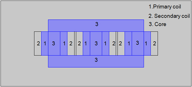
FEA numerical methods subdivide a region into discrete elements with interconnecting nodes. An electromagnetic (EM) partial differential equation (PDE) is solved in separate elements then combining elements to predict behavior in a region. Magnetic transformers have cores forming a closed magnetic flux path. A 3-phase transformer has 3 sets of primary and secondary windings where we assume each set is wound on one leg of a core assembly. This resembles the 3 single-phase transformers sharing a joined core as in Fig. 1. This simple transformer topology is suitable as a design template for the materials comparisons reported below.
3-phase transformer FEA 2D model.

The EM PDE model is solved in the time domain for a line frequency range of 50 Hz–10 kHz. Several important design parameters such as the core geometry, the magnitude of the input voltage, line frequency, number of turns in the coils, and conductor size and distribution are parameterized to be easily varied. A transformer operates by the principle of Faraday induction where induced voltage (V in) in a coil is proportional to the rate of change of magnetic flux (φ) and the number of coil turns (N) [Eq. (3)].
 $${V_{{\rm{in}}}} = {{N{\rm{d}}\varphi } / {{\rm{d}}t}}\quad .$$
For an angular frequency of ω and the magnetic circuit with an area of A B at a flux density of B, it follows that
 $${V_{{\rm{in}}}} = N\omega {A_{\rm{B}}}B\quad .$$
For a magnetic core with a window area of A j, we note the following constraint:
 $$NI = k{A_{\rm{j}}}\,{j_{{\rm{max}}}}\quad ,$$
where I is the primary current, k is a certain fraction of the window area A j, and j max is the allowable maximum current density. From Eqs. (4) and (5), we find that
 $${A_{\rm{j}}}{A_{\rm{B}}} = {{{V_{{\rm{in}}}}I} \over {k\omega B{j_{\max }}}}\quad .$$
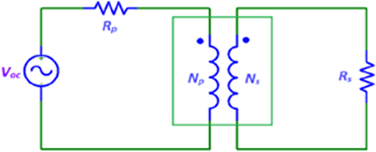
Equation (6) implies that the size of the optimally designed transformer changes proportional to ω−3/4. Reduced size could potentially lead to reduced cost and increased power density. This is a primary motivation to operate the transformer at a higher frequency. However, from a material perspective, the high frequency operation will incur increased power loss per unit volume which can outweigh advantages of the reduced size in some cases. The trade-offs largely depend on the properties of the core materials. Here, we present FEA simulations for several core materials. We assume multiple turn primary and secondary windings to have wire diameters less than the frequency-dependent skin depth. A primary winding is connected to a primary resistor, R p, and AC voltage source, V ac, and a secondary winding is connected to a load resistor, R s, shown in Fig. 2.
Transformer circuit diagram.

The model is solved in time domain for a line frequency of 50 Hz–10 kHz with 8 kV power supply and output power 100 kW for the first 4 cycles. Note that the FEM model is an integral part of the circuit model shown in Fig. 2 as represented by the central square box containing the transformer and hence the result includes any effect of leakage flux. However, the loss component associated with leakage flux resulting in eddy currents at the core surfaces is not included due to difficulties in quantitative modeling. Design parameters include core geometry, input voltage magnitude, line frequency, coil turn numbers and coil conductor size, and resistivity. These are parameterized to allow design optimization. Flux density distributions in transformer cores are calculated to evaluate magnetic losses using Steinmetz relationships for transformer grade Si steel compared with Metglas and various MANCs including Co- and FeNi-based MANCs.
B. Results and discussion
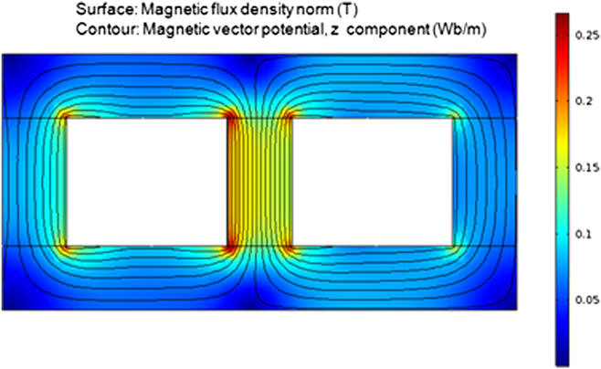
Figure 2 shows a circuit diagram of a single-phase transformer. We extend this model to 3-phase transformers shown in Fig. 3. For simplicity, the three phases were modeled to be electrically independent while coupled magnetically. The finite element mesh was refined until the simulation results show clear convergence.
Flux distribution of the 3-phase transformer.

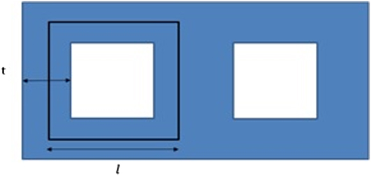
Figure 3 shows a calculated flux distribution for a typical transformer with primary and secondary coils and a ferromagnetic core. The primary coil receives an AC current input. Mutual induction causes voltage across a secondary coil. A magnetic core concentrates flux to minimize leakage losses. We define the core length as L and path thickness as t as is shown in Fig. 4. The design constraints [Eqs. (4) and (5)] of a transformer are given in Sec. IV.A. For simplicity, we add several geometrical constraints for the transformer. For example, we set the core window to be a square with its side fixed at 2t, where t is the width of the flux path as shown in Fig. 4. The average flux path is 4l and l is set equal to 3t. The length of the core perpendicular to the plane shown in Fig. 4 is also set to 3t. With these additional constraints, the transformer geometry is uniquely defined for a given value of B and j max. The number of primary turn N is also uniquely determined by the following expression:
 $$N = \sqrt {{{{V_{{\rm{in}}}}\,{j_{\max }}} \over {6\omega BI}}\quad .}$$
Transformer core model.

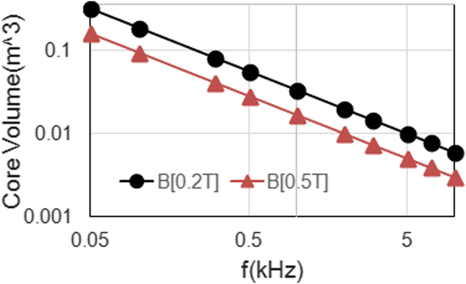
The core size of the 3-phase transformer designed with these constraints is illustrated in Fig. 5 for the primary voltage V in = 8 kV, current density j max = 2.2 A/mm2, current I = 12.5 A for two cases of peak flux density B = 0.2 and 0.5 T. One can realize a very significant reduction in size by increasing the frequency from 50 Hz to 10 kHz if one limits the core loss increase as the frequency increases through judicious materials choice.
Transformer core volume versus frequency at B = 0.2 and 0.5 T.

The juxtaposition of EM response and materials performance is addressed through introduction of realistic models for the frequency and induction dependence of magnetic losses. While the micromagnetic (nanomagnetic) processes that determine these losses are of fundamental interest in materials development, we forgo such discussion using lumped response functions as expressed in empirical parameterized loss functions that allow us to assess materials performance in specific component design. To this end, core loss was parameterized in a Steinmetz equationReference DeGeorge, Deveraj, Keylin, Cui and McHenry31 for standard transformer grade Si-steel, Co-rich MANCs, and FeNi-based MANCs. We decompose the loss into three components reflecting micromagnetic mechanism inherent in hysteresis, eddy current, and excess losses and fit a classical Steinmetz equation to each.Reference Aronhime, DeGeorge, Keylin, Ohodnicki and McHenry18,Reference Steinmetz50 The fitting parameters are listed in Table I. For Metglas, the parameters are taken from the literature.Reference Islam, Guo and Zhu51 For Ferrite and FINEMET, the parameters were taken from Hitachi Metals Ltd. This analysis of component size reduction with higher frequency operations, considering the frequency and induction scaling of power density and power losses is analogous to previously reported designs of rotating electrical machines.Reference Silveyra, Leary, DeGeorge, Simizu and McHenry52,Reference Silveyra, Xu, Keylin, DeGeorge and Leary53 Since this work, the discovery of new FeNi-based MANCs with lower losses and lower material costs than the Co-based MANCs have been reported.Reference Aronhime, DeGeorge, Keylin, Ohodnicki and McHenry18,Reference Aronhime, Zhoglin, Keylin, Jin, Ohodnicki and McHenry20 The Co-based MANCs allow for permeabilities tunable to very low values attractive for inductor applications to replace distributed gap materials, but the FeNi materials with permeabilities tunable to larger values may be more interesting for transformer applications. Both Co-based and FeNi-based MANCs have mechanical properties that indicate less brittleness than commercial FINEMET materials. FeNi-based MANCs also replace more expensive Co with less expensive FeNi components.
Steinmetz parameters and relative permeability of Si Steel, Metglas, Co-based MANC, Ferrite (Fair rite 97), commercial Fe-based nanocomposites (FT-3TL), and FeNi-based MANCs. Equation (2) was used for Si steel and MANCs. For Metglas, Ferrite, and FT-3TL, a single term formula  ${C_{{\rm{loss}}}}{f^\alpha }{B_{\rm{p}}}^\beta$ was applied.

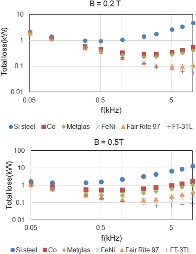
The total power loss (copper loss and core loss) including Joule heating in the coil is shown in Fig. 6 for the four core materials. In Figs. 6(a) and 6(b), the loss decreases to about 500 Hz for all cases due to the size reduction with constant flux density shown in Fig. 5 resulting in a reduction in copper losses. However, the loss begins to increase above this for Si steel. Metglas and Co-rich MANCs also begin to show increase in power loss above 1 kHz. Metglas shows significantly reduced power loss than Co-rich MANCs. However, Ferrite (Fair rite 97), FeNi-based MANCs, and commercial Fe-based nanocomposites (FT-3TL) show continued decrease of power loss 10 kHz at B = 0.2 T (Table II).
Total loss of a 100 kVA transformer with Si Steel, Metglas, Co- and FeNi-based MANCs at (a) B = 0.2 T and (b) B = 0.5 T.

Chemistries and magnetic properties for Si steel, Co-based MANCs, FeNi, Metglas, Ferrite, and Finemet alloys. Coercivity, saturation flux density, thickness, permeability, and loss of these materials are given. For Si steel, Co-based MANC and FeNi-based MANC data are collected from our published paperReference Aronhime, DeGeorge, Keylin, Ohodnicki and McHenry18,Reference Silveyra, Leary, DeGeorge, Simizu and McHenry52 and for Metglas, Ferrite and Finemet are taken from Hitachi.63

On the other hand, in Fig. 5(b), ferrite shows rise in power loss above 3 kHz at B = 0.5 T. Note that these comparisons are made for a fixed peak flux density of 0.2 and 0.5 T for the common core size that is shown in Fig. 5. By increasing the peak flux density, the core size will be decreased resulting in lower copper loss for a fixed conductor diameter. However, it comes at an expense of the higher core losses and therefore total losses at low frequency decrease as shown in Fig. 6(b), but they increase for higher frequencies. The neglect of leakage flux induced eddy current losses here is something that could significantly modify these predictions. This additional loss contribution will be driven by differences in resistivities and permeabilities of the various alloys as well as the details of how flux is flowing throughout the cores, in particular the degree to which normal or leakage flux is present. In this paper, we are looking leakage flux which is minimal, but in certain case, the leakage flux is big.
These results show that MANCs are theoretically predicted to be superior to ferrites and amorphous materials for high-f high power applications under the design and modeling assumptions applied in this work. Due to its relatively low loss density, high saturation flux density, and high Curie temperature, the MANC is promising for high power density designs. Although the core loss is moderate and the cost is low, ferrite cores may not be preferred in the SST application because of their low saturation flux density (∼0.2–0.3 T), which results in a larger core size at a fixed switching frequency. A drawback to nanocrystalline (and other tape wound and laminated core) materials is that the losses are low only when flux flows along the direction of the tape surface; any significant flux which flows normal to the tape surface (e.g., between tape layers, or into the external broad surface of the tape) creates large eddy current losses in the core. This should be noted when the transformer design requires a high leakage flux.Reference Cougo and Kolar34,Reference Beddingfield, Bhattacharya and Ohodnicki35 Ferrite, on the other hand, has the advantage of being an isotropic ceramic material, allowing flux to flow in any direction in the core without excess losses. (Various “distributed gap” core materials, such as powdered iron, also have the isotropic advantages of ferrite, but their permeabilities are generally too low for most transformer applications.) In the future, it may be possible to further improve performance relying on spatially varying permeability made possible by strain annealing MANCs,Reference Leary, Keylin, Devaraj, DeGeorge, Ohodnicki and McHenry13,Reference Kernion, Miller, Shen, Keylin, Huth and McHenry14,Reference Aronhime, DeGeorge, Keylin, Ohodnicki and McHenry18 and by coupling FEA EM loss analysis with FEA thermal modeling.
V. COST COMPARISONS
Increasingly, issues of materials criticality and economicsReference Eggert, Wadia, Anderson, Bauer, Fields, Meinert and Taylor54 are important in materials choices for applications. Co is not currently on recent materials criticality lists, but it has been in the past and its potential criticality and costReference Kurniawan, Keylin and McHenry55 should be considered in component designs. In the benchmarks presented herein, the Fe–Ni-based MANCs compare favorably with Co-based MANCs on a cost per weight basis. This is both due to the significantly lower cost of elemental Fe and Ni as compared with Co as well as the possibility of cheaper ferrous alloys containing the requisite glass forming elements (Nb, Hf, Zr, B, Si, etc.) The glass formers which act as nanocrystal growth inhibitors, Zr, Nb, and Hf,Reference Iwanabe, McHenry, Lu and Laughlin56–Reference Willard, Laughlin and McHenry57 are chosen on the basis of cost and process compatibility. For example, Nb is more often chosen as it poses fewer problems for casting in air or with an inert gas shroud. Optimization of glass former compositionsReference Miller, Wise, Leary, Laughlin, Keylin, Huth and McHenry58,Reference Kernion, Miller, Shen, Keylin, Huth and McHenry59 is achieved in each different alloy class requiring careful consideration of the stability of secondary crystallization products.Reference Long, Ohodnicki, Laughlin, McHenry, Ohkubo and Hono60,Reference Ohodnicki, Cates, Laughlin, McHenry and Widom61 Because of the replacement of Co and the larger differences between primary and secondary crystallization temperatures,Reference DeGeorge, Zhoglin, Keylin and McHenry19 Fe-rich, FeNi-based MANCs are considered more suitable for high-f transformer designs.
A similar comparison between MANCs and steels or ferrites identifies them as having higher cost per weight. However, in comparing economic benefits between MANCs and steels, it is important to consider all system level cost reductions enabled by the high-f design. In comparison with ferrites, the impact of significantly lower saturation flux densities must be considered in limiting achievable power densities at comparable frequencies. In that reduced core size also allows for reduction in winding volume additional economic efficiency is suggested. For all of these reasons, MANCs and notable recently reported FeNi-based MANCs may have economic benefits in the context of some designs as compared with traditional materials in SST applications.
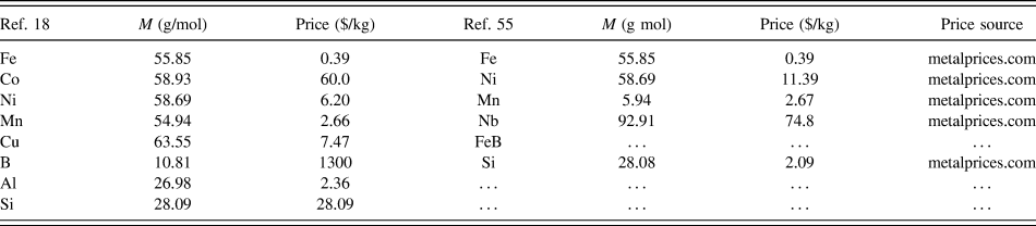
Kurniawan et al.Reference Kurniawan, Keylin and McHenry55 and Aronhime et al.Reference Aronhime, DeGeorge, Keylin, Ohodnicki and McHenry18 have reported the individual prices of the precursors used in the synthesis of their compositions. Among the late transition metals, Co is the most expensive at $60/kg, while Fe is the least expensive at only $0.39/kg.62 Due to the high price of Co ($60/kg), all Co-based alloys are generally more expensive than Fe-based alloys which is shown in Table III. Some improvement is possible for the cost of Co-based alloys by modifying feedstocks and alloy compositions to deal with the relatively high cost of elemental B, which can be a major factor in the cost of the overall feedstock compositions if pure B is required at a price of ∼$1300/kg.
Molar masses (g/mol) and prices ($/kg) of all the precursors used in the synthesis of FINEMET and FeNi-based MANC materials investigated in Refs. Reference Aronhime, DeGeorge, Keylin, Ohodnicki and McHenry18 and Reference Kurniawan, Keylin and McHenry55. The data presented here are taken from sources Ref. 62.

VI. CONCLUSIONS
2D FEA of 3-phase SST’s at 50 Hz–10 kHz frequencies considered materials for designs aimed to control high-f losses and achieve higher power densities. FeNi-based MANCs allow for smaller transformers at equivalent power when compared with both Si steels, Metglas and Co-based MANCs. The commercial Fe-based alloy FT-3TL shows lower losses as compared with the FeNi-based MANC. However for applications in which mechanical properties are important or advanced core fabrication and processing techniques such as strain annealing are used, the FeNi-based alloys may show some distinct advantages. Low losses and reduced weight of the magnetic core and copper will influence system level costs by taking advantage of the higher inductions of high efficiency MANC alloys. And further improvements in future SST design optimization may be possible through consideration of engineered spatially varying permeability made possible by strain annealing MANCs. A key enabler for the successful realization of such advanced designs will be sufficiently robust mechanical properties offered by more advanced MANC alloys than the commercial Fe-based systems.
ACKNOWLEDGMENTS
This work is supported in part by the DOE SunLamp and DOE EERE AMO Programs. Federal Award number: DE-OE0000856 Flexible Large Power Solid State Transformer, Subaward No. 2017-0230-01.