I. INTRODUCTION
Graphite-like carbon (GLC) films, developed from diamond-like carbon (DLC) films, are a type of amorphous carbon film mainly composed of sp 2 hybrid bonds. It not only presents the same excellent tribological properties as that of DLC films, but also shows good mechanical properties and load-bearing capacity. Reference Hong, Tu, Li, Liu, Sun, Mao and Peng1–Reference Guan, Lu and Wang4 Currently, GLC films have primary application in tools and molds owing to their excellent performance. Compared to the conventional ceramic-coated tools, a cutter coated with a GLC film has a significantly longer life cycle. In addition, GLC films show great potential for surface protection and lifetime extension of the mechanical components working in water or oil lubricating environments and key friction components in the medical industry. Reference Fox, Jones, Renevier and Teer5–Reference Olivares, Rodil and Arzate8 Hence, GLC films provide a new approach to solve several problems facing DLC films, such as the high internal stress, relatively poor environment adaptability, and high-temperature stability, and opens up the possibility of implementing amorphous carbon films in more rigorous conditions. Reference Chen, Wang, Li, Ji, Wu, Lv, Liu, Fu and Zhou9 However, present literature mainly concentrates on the study of pure GLC films, and less attention has been paid to the influence of element doping on the microstructure and performance of GLC films.
W, a type of typically strong carbide-forming metal, easily combines with carbon to form WC or W2C crystals, which possess low diffusivity and high thermostability. Reference Yue, Wang, Fu, Gao, Yu and Liu10 Numerous studies have shown that Reference Qiang, Gao, Zhang, Wang, Zhang and Zhang11–Reference Fu, Mei, Fu, Liu and Chu16 in a certain range of content, W-doping is an effective way to improve the mechanical strength, toughness, thermostability, and oxidative stability of DLC films. Hence, currently, W-doped DLC films are an important topic in the study of metal-doped DLC films. However, to the best of our knowledge, research on W-doped GLC films, especially on the relationship between the quantity of W-doping and the microstructure and performance of films, has not been systemically reported.
In this study, W-doped GLC films were successfully deposited under different W target currents by adopting an unbalanced plasma enhanced magnetron sputtering system. Moreover, the impact of W content on the microstructure and performance of the W-doped GLC (W-GLC) films is discussed in detail.
II. EXPERIMENTAL ANALYSIS
A. Film deposition
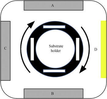
All the W-GLC films were deposited under an unbalanced plasma enhanced magnetron sputtering system. As illustrated in Fig. 1, in total, there are three targets, labeled A, B, and C, in the vacuum chamber. Here, A and B are graphite targets, acting as a carbon source in this experiment. C is a tungsten target, which is used to dope tungsten and fabricate the interlayer. D is an additional ion source, controlled by a direct-current power source with a maximum current of 20 A, providing additional plasma to assist the deposition of the W-GLC films.
Sketch of the unbalanced plasma enhanced magnetron sputtering system.

In this experiment, the films exhibit the structure of W-GLC/interlayer/substrate. A high-speed steel (W6Mo5Cr4V2) was used as the substrate; moreover, to observe the cross-sectional morphology and the structure of the W-GLC films, a silicon wafer was also chosen as the substrate. All the high-speed steel substrates used in this experiment were preprocessed via polishing and cleaned using absolute ethyl alcohol and acetone for 30 min sequentially. The four types of the deposited W-GLC films were labeled as 1#, 2#, 3#, and 4#.
The main processes of the deposition are summarized as follows:
-
(i) The inner chamber with substrates was vacuumed to approximately 10−3 Pa and then heated to 200 °C.
-
(ii) After the pressure inside the chamber dropped to 6 × 10⁻³ Pa, the substrates were etched with Ar+ ions under a bias voltage of 60 V for 30 min to remove the native oxide layer on the surface of the substrates.
-
(iii) Targets A, B, and C were turned on and cleaned for 40 min simultaneously.
-
(iv) The graphite targets (A and B) were turned off, and the current of target C was adjusted to 2.0 A. Thereafter, a tungsten interlayer was deposited for 30 min.
-
(v) Targets A and B were switched back on, and their currents were adjusted to 3.5 A and 3.6 A, respectively. Thereafter, a WC interlayer was deposited for 10 min.
-
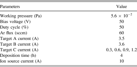
(vi) The current in the tungsten target (C) was adjusted to 0.3 A (0.6, 0.9, and 1.2 A), and subsequently, the W-GLC films were deposited (detailed technical parameters are listed in Table I).
Deposition parameters of the W-GLC films.
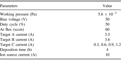
It is important to note that the authors have already discussed the impact of ion source on the deposition quality of GLC films in one of their previous studies and have found that the film would achieve the best quality when the ion source current is 10 A. Hence, the ion source current in this study is set as 10 A.
B. Film characterization
The surface morphology and cross-sectional microstructure of the W-GLC films were analyzed using a field emission scanning electron microscope (SEM; Nova Nano SEM450/650, FEI Company, Santa Barbara, California, with energy dispersive spectroscopy [EDS]). The cross sections of the films were obtained by breaking the silicon substrate after film deposition. The thickness and surface roughness of the W-GLC films were measured by employing OLS4000 three-dimensional surface profilometry. To measure the thickness of the films, the samples were marked with a marker pen after the ultrasonic cleaning step. The markings were removed using alcohol after the deposition step, and the thickness of the films was obtained by measuring the difference in height of the uncoated and coated areas of the samples. A HR800 Raman spectrometer (Horiba J.Y., Montpellier, France) with a laser wave length of 532 nm was used to characterize the bonding structure of the film. The structure of the deposited films was observed using an Ultima IV type x-ray diffractometer (Rigaku Corporation, Tokyo, Japan). Further investigation on the microstructure characterization of the films was conducted using high-resolution transmission electron microscopy (HRTEM) and selected area electron diffraction (SAED) via Tecnai G2 F20 S-TWIN transmission electron microscope (FEI Company) operated at 200 kV. The hardness and elastic modulus of the films were determined by adopting a Nano Indenter G200 nanomechanical system (Agilent Technologies, Shanghai, China). A MFT-4000 multifunctional material surface property tester (Huahui Instrument Technology, Lanzhou, China) was used to estimate the adhesion strength between the substrates and the films. The tribological properties of the studied films were measured using a rotating-type ball-on-disc tribometer (MSTS-1, home-made, Beijing, China). The friction tests were performed at room temperature with a load of 12 N and a sliding speed of 100 rpm for 480 min. The diameter of the grinding balls (9Cr18) is 9.525 mm. The wear tracks and wear rate of the W-GLC films were analyzed using the three-dimensional surface profilometry (OLS4000) after the friction tests. The morphology observation and component analysis of the worn surfaces of the counterpart balls were completed using the field emission SEM (Nova Nano SEM450/650, with EDS). The composition of the transfer film of the selected W-GLC film was analyzed using an x-ray photoelectron spectrometer (XPS; Escalab 250Xi, Thermo Fisher Scientific, Shanghai, China). Furthermore, to facilitate comparison in the following sections, the pure GLC film was first deposited, and then its performance was tested using the aforementioned instruments. Specific data of the W-GLC film are as follows: the surface roughness is 7.56 nm, the hardness is 8.423 GPa, the elastic modulus is 91.875 GPa, and the adhesion strength is 27 GPa. When the film is tested at a load of 12 N and a sliding rate of 100 rpm for 30 min, the average friction coefficient is 0.01, and the wear rate is 1.75 × 10⁻¹⁶ m3/N m.
III. RESULTS AND DISCUSSION
A. Composition and microstructure
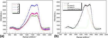
Owing to its sensitivity to the bonding structure and cluster size, Raman spectroscopy is recognized as an accurate and useful analysis method to investigate the microstructure of amorphous carbon films. Reference Ferrari and Robertson17 According to Fig. 2(a), which shows the Raman spectra of the W-GLC films deposited under different W target currents, all the films deposited in our experiment exhibit typical Raman spectrum features of an amorphous carbon film. It can be seen that none of the Raman spectra contain any sharp peak in the range of 600–2000 cm−1, but they all present an asymmetric intensity distribution, which can be decomposed into D and G peaks using Gaussian fitting. The result of the Gaussian fitting of sample 2# is individually illustrated in Fig. 2(b) as a representation. The D peak, which lies at approximately 1371 cm−1, is generated by the breathing modes of 6-fold carbon rings and is an indication of the structure disorder of the carbonaceous material. Reference Ferrari and Robertson17,Reference Ferrari and Robertson18 In addition, the G peak, which is located at approximately 1567 cm−1, is formed by stretching vibration of all the pairs of sp 2 carbon atoms in both rings and chains, and is an indication of the symmetry and order degree of carbonaceous material. Reference Ferrari19,Reference Ferrari, Kleinsorge, Morrison, Hart, Stolojan and Robertson20 The detailed Gaussian fitting results of all the samples are summarized in Table II. It is generally accepted that the relative intensity ratio of the D peak to the G peak, I D/I G, can qualitatively describe the relative proportion of sp 3 and sp 2 hybrid structures; lower the ratio, higher the proportion of sp 3 hybrid structure and vice versa. Reference Robertson21 The I D/I G ratios of all the films deposited in this study are greater than 4.0, and are 30 times greater than that of the DLC films mainly composed of sp 3 hybrid structure. Reference Siegal, Tallant, Martinez-Miranda, Barbour, Simpson and Overmyer22 Therefore, it is concluded that most of the C in the film exists in the form of sp 2 hybrid structure, and the film exhibits GLC structural features.
Raman spectra of the W-GLC films deposited under different W target currents (a) four types of W-GLC films and (b) the corresponding Gaussian fitting results for sample 2#.

Gaussian fitting of Raman spectra of the GLC films.

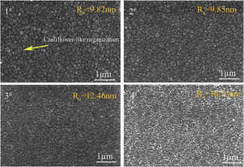
Figure 3 shows the surface morphology and the surface roughness (Ra) of the W-GLC films deposited under different W target currents. The Ra of each film is the average value that is measured in three selected flawless areas of the film surface using three-dimensional surface profilometry. It is clear that the surface morphology of each film shows no significant differences, and is composed of numerous closely packed nanosized particles or clusters, exhibiting a cauliflower-like feature. Compared to pure GLC films, the surfaces of all the W-GLC films deposited in this experiment are relatively rough, and with the increase in the W target current, the Ra of the studied films increases from 9.87 nm to 16.13 nm.
Surface morphologies and surface roughness of the W-GLC films deposited under different W target currents (1#) 0.3 A, (2#) 0.6 A, (3#) 0.9 A, and (4#) 1.2 A.
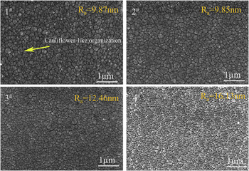
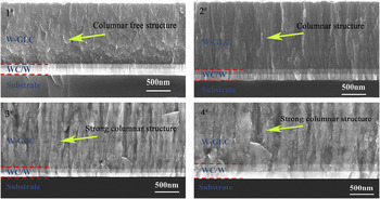
Figure 4 shows the cross-sectional microstructure of the W-GLC films deposited at different W target currents. The cross section is composed of the carbon film and the transition layer, where the thickness of the carbon film is approximately 1.4 μm and that of the transition layer is 350 nm with a pure W layer that is approximately 200 nm thick and a WC layer that is approximately 150 nm thick. All the transition layers present a weak columnar structure, but the microstructure of the upper carbon film changes significantly with the increase in the W target current. In particular, when the W target current is 0.3 A, the cross section of the 1# film exhibits a compact and columnar-free structure with fine overall uniformity. As the W target current increases to 0.6 A, the cross section of the 2# film presents a feature of slight columnar growth with a corresponding drop in compactness. When the W target current further increases to 0.9 and 1.2 A, the cross section of the 3# and 4# films shows a distinct columnar structure, which indicates the loosening of the film.
Cross-sectional morphologies of the W-GLC films deposited under different W target currents (1#) 0.3 A, (2#) 0.6 A, (3#) 0.9 A, and (4#) 1.2 A.

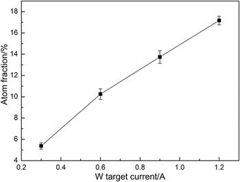
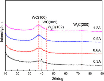
Figure 5 illustrates the W atom content of the deposited W-GLC films. It is clear that with the increase in the W target current, the W atom content of each film is 5.38%, 10.25%, 13.74%, and 17.17%, respectively. The phase composition of the studied W-GLC films was investigated using grazing incidence x-ray diffraction (GIXRD) and the corresponding results are shown in Fig. 6. It is evident that the main source of the diffraction peaks in the recorded GIXRD spectra are from the WC phase and correspond to WC (100) and WC (001) planes. Furthermore, with the increase in the W target current, a small amount of W2C phase [corresponding to W2C (102) and W2C (200) planes] may exist in the film.
W atom content of the W-GLC films deposited under different W target currents.

GIXRD patterns of the W-GLC films deposited under different W target currents.

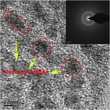
Figure 7 shows the HRTEM images and SAED pattern of the W-GLC film deposited at a W target current of 0.6 A. As shown in Fig. 7(a), the SAED pattern of the 2# film shows multiple distinctly broadened diffraction rings, providing significant characteristic diffraction information of amorphous materials. From the HRTEM images, it is observed that tiny nanocrystalline particles are evenly embedded in the amorphous carbon network, exhibiting a typical nanocrystalline/amorphous composite structure. Based on the results of the GIXRD, it is predictable that the embedded nanocrystalline particles are WC or W2C.
HRTEM images and SAED pattern of the W-GLC film deposited at a W target current of 0.6 A.

B. Mechanical properties
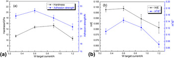
The mechanical properties of the W-GLC films deposited under different W target currents are shown in Fig. 8. When the W target current increases from 0 A to 0.9 A, the hardness of the films monotonously increases from 8.423 GPa to a maximum value of 15.262 GPa with an increase rate of 81%, following which it drops to 10.631 GPa as the W target current further increases to 1.2 A. This behavior shows that doping a moderate amount of tungsten into the pure GLC film can significantly improve the hardness of the film, while excessive doping will cause a decrease. In addition, the adhesion strength, H/E (which determines the limit of elastic behavior under surface contact conditions and represents the elasticity of the film), and H 3/E 2 (which determines the ability to resist the plastic deformation and represents the toughness of the film) exhibit similar change rules. Both H/E and H 3/E 2 show a tendency of increasing first and subsequently decreasing with the increase in the W target current, and reach their maximum values when the W target current is 0.6 A. This observation demonstrates that doping tungsten in a moderate amount not only significantly improves the hardness, but also contributes to better adhesion strength, elasticity, and toughness of the pure GLC film.
Mechanical properties of the W-GLC films deposited at various W target currents (a) hardness and adhesion strength and (b) H/E and H 3/E 2.

C. Tribology properties
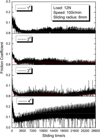
The friction coefficients between the W-GLC films deposited under different W target currents and steel balls are shown in Fig. 9. The friction tests were conducted at a load of 12 N and a sliding speed of 100 rpm for 480 min at room temperature under air condition. As illustrated in Fig. 9, when the W target current increases from 0.3 A to 0.9 A, the friction coefficient of the W-GLC films tends to be stable with a minor fluctuation after a short running-in period in the initial phase of the friction test. Now the friction coefficients of the 1# and 2# films remain at a very low value throughout the whole process, presenting an excellent lubrication performance, while a very low friction coefficient is observed for the 3# film only in the first 6 h, and thereafter, the friction coefficient shows a distinct increasing tendency. When the W target current is 1.2 A, the friction coefficient of the 4# film immediately increases after a decrease during the running-in period, and shows considerable fluctuation with the advancement of the test time.
Friction coefficient of the W-GLC films deposited under different W target currents (1#) 0.3 A, (2#) 0.6 A, (3#) 0.9 A, and (4#) 1.2 A.
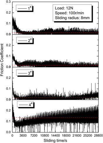
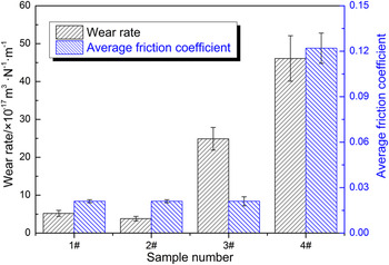
Figure 10 shows the average friction coefficient and wear rate of the studied films. When the W target current increases from 0.3 A to 0.9 A, the average friction coefficient of the films, which only increases from 0.018 to 0.021, does not present a distinct change; however, as the W target current keeps increasing to 1.2 A, the average friction coefficient increases abruptly to 0.12. Moreover, with the increase in the W target current, the wear rate of the W-GLC films shows a change rule of decreasing first and increasing subsequently, and reaches a minimum value of 3.8 × 10⁻¹⁷ m3/N·m at 0.6 A, which presents an outstanding wear resistance. This behavior indicates that doping a moderate amount of tungsten into the pure GLC film can significantly increase the wear resistance of the film without increasing the friction coefficient.
Average friction coefficient and wear rate of the studied W-GLC films.

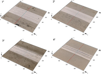
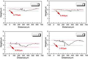
To further analyze the friction and wear mechanisms of the studied films, the worn surface was carefully observed, and the wear depth was calculated. From Figs. 11 and 12, it can be seen that the wear degree of each film is less, and numerous parallel furrows with different width and depth along the sliding direction are distributed in the central part of the wear tracks, presenting a comparatively typical abrasive wear. However, the wear depth of the W-GLC films deposited under different W target currents is not the same. As shown in Fig. 12, the wear depth has a minimum value of 464 nm when the W target current is 0.6 A, while it reaches a maximum depth of 1052 nm when the W target current is 1.2 A. This result coincides with the change rule of the wear rate.
Three-dimensional (3D) worn morphology of the W-GLC films deposited under different W target currents (1#) 0.3 A, (2#) 0.6 A, (3#) 0.9 A, and (4#) 1.2 A.

Wear depth of the W-GLC films deposited under different W target currents (1#) 0.3 A, (2#) 0.6 A, (3#) 0.9 A, and (4#) 1.2 A.

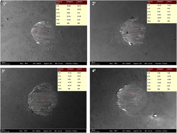
Figure 13 shows the morphology and component analysis of the worn surfaces of the counterpart balls. It can be seen that the surfaces of all the counterpart balls are covered with a clear transfer film except the one that slides against the film deposited under the W target current of 1.2 A, which causes a noticeable material loss of the counterpart ball. Through the component analysis of the selected areas (in red boxes) in the worn surfaces, it is found that the worn surfaces of 1#, 2#, and 3# contain a high amount of C, which shows the main component of the transfer film on the worn surfaces should be amorphous carbon. However, the worn surface of 4# is mainly composed of Fe and Cr, which are only the main components of counterpart balls. Moreover, O and W are found to exist in all the worn surfaces. The existence of the former may be due to the oxidation of the worn surfaces, while the latter may come from the WC or W2C nanocrystallines of the films that transfer to the worn surface.
Worn morphology of the counterpart balls sliding against the four types of W-GLC films (1#) 0.3 A, (2#) 0.6 A, (3#) 0.9 A, and (4#) 1.2 A.

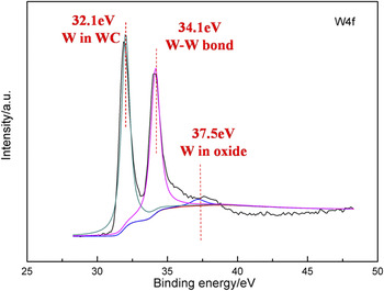
Further investigation on the transfer film of the 3# film by XPS analysis is shown in Fig. 14. It can be seen that the W 4f spectrum of the tested transfer film is mainly characterized by bonding energies of 32.1 eV and 34.1 eV, which are associated with the presence of WC and W, respectively. On the one hand, it is shown that some of the W atoms are dissolved in the amorphous carbon matrix forming the WC phase, while some other W atoms in the film remain in the form of elementary substance. On the other hand, it is also proved that hard WC nanocrystallines have entered the friction interface and partly transferred to the surface of the counterpart ball during the friction process, which may affect the tribology behavior of the film. In addition, there is a considerably weak peak existing in the spectrum with a binding energy of 37.5 eV, corresponding to WO3. Reference Díaz-Reyes, Delgado-Macuil, Dorantes-García, Perez-Benítez, Balderas-López and Ariza-Ortega23 This may be due to the effect of flash temperature from friction, which causes oxidation of elemental W that enters into the friction interface, and hence, forms WO3.
W (4f) core level XPS spectra of transfer film of 3# film.

D. Discussion
The properties of amorphous carbon films are often closely related to its microstructure and composition. Reference Liang, Wang, Huang, Tsai and Yang24–Reference Dai, Wang and Wang28 In this study, when the W target current is relatively low (0.3 and 0.6 A), the strong Ar+ bombardment can effectively sputter away the rough groove-like growth front, enhance the mobility of atoms on the protuberances, and consequently, limit the formation of a columnar structure. Reference Pei, Chen, Shaha, Hosson, Bradley, Voronin and Čada29,Reference Shaha, Pei, Martinez-Martinez, Sanchez-Lopez and Hosson30 Hence, the films have relatively smooth surfaces and exhibit a compact columnar-free structure when the W target current is 0.3 A and a structure of slight columnar growth when the W target current is 0.6 A. As the W target current is relatively high (0.9 and 1.2 A), the Ar+ bombardment is unable to offset the unfavorable effects due to the excessive rapid metal deposition rate. During the film deposition process, the diffusion and accumulation of the subsurface atoms or radicals to form islands of different sizes distributed irregularly on the film surface would roughen the film surface and lead to a loose columnar structure. Reference Peng, Barber and Clyne31,Reference Lifshitz, Edrei, Hoffman, Grossman, Lempert, Berthold, Schultrich and Jäger32
The mechanical properties of the studied films show significant differences with the increase in the W target current. This is because, when the W target current is relatively low (0.3 and 0.6 A), W easily combines with C to form WC or W2C nanocrystallines, which are of low diffusivity and high thermostability. These hard nanocrystallines uniformly embed inside the amorphous carbon matrix, and form a typical nanocrystalline/amorphous composite structure, which plays a role in dispersion strengthening. Reference Chen, Wang, Li, Ji, Wu, Lv, Liu, Fu and Zhou9 Therefore, the hardness, adhesion strength, elasticity, and toughness of the studied films all exhibit an increasing tendency. However, with further increase in the W target current (0.9 and 1.2 A), the deposition rate of W target increases significantly, and the excessive formation of WC or W2C nanocrystallines supersaturates the dispersion strengthening. The large amount of these hard nanocrystallines even become the defects of the film, which break the connectedness and integrality of the carbon network, inducing an increase in the sp 2 hybrid bond content of the film. Reference Voevodin, O'Neill and Zabinski13,Reference Wang, Lee, Ahn and Han33 Hence, the hardness, adhesion strength, elasticity, and toughness of the studied films reduce considerably in this case. In addition, the relatively loose structure is another important reason for the reduction in the mechanical properties of the W-GLC films deposited under W target currents of 0.9 and 1.2 A.
When the W target current increases from 0.3 A to 0.9 A, the friction coefficients of the studied films all remain at a very low value. The main reasons for this behavior are explained as follows: first, the carbon in the W-GLC films mainly exists in the form of sp 2 hybrid structure, which determines a few quantities of the surface dangling σ bonds. Generally, the surface dangling σ bonds contribute to strong covalent interaction between the worn surface and the steel ball. Reference Yue, Wang, Fu, Gao, Yu and Liu10 Therefore, the film cannot easily adhere to the steel ball during the course of friction. Second, numerous sp 2 clusters inside the film have very low shear strength and are prone to be scraped from the film surface and adhere to the surface of the steel ball, forming a transfer film. The existence of the transfer film avoids direct contact between the friction pairs and reduces the contact stress by widening the contact area. Reference Wang, Wang and Xue7,Reference Wang, Wang, Li, Chen and Xue34 Third, according to present literature, WC nanocrystallines formed inside the film through W-doping have high thermostability. When they are dispersedly distributed inside the amorphous carbon matrix, the thermostability of the film is improved, and hence, the relaxation of carbon network and the graphitization generated by friction heat are significantly reduced. Reference Mrabet, Abad, López-Cartes, Martínez-Martínez and Sánchez-López15,Reference Fu, Mei, Fu, Liu and Chu16 This may be another important reason why the W-GLC films deposited in our experiments have very low friction coefficients. Moreover, when the W target current is 1.2 A, the friction coefficient of the film increases significantly. The reasons for this are explained as follows. At first, the excessive content of WC or W2C nanocrystallines in the film supersaturates the dispersion strengthening, which leads to a considerable reduction in the mechanical properties. At the same time, excess rapid metal deposition rate loosens the structure of the film. Hence, the hard nanocrystallines easily enter the friction interface in a considerable amount and combine into larger crystals during the friction process, which breaks the stability of the friction interface. In this case, it is very difficult for the matched ball to form a continuous and stable transfer film on the worn surface.
With the increase in the W target current, the wear rate of the film presents a change rule of decreasing first and increasing subsequently. The reasons are listed as follows: when the W target current is relatively low (0.3 and 0.6 A), the film has a relatively compact structure, and the dispersion strengthening generated by WC or W2C nanocrystallines leads to better hardness, adhesion strength, elasticity, and toughness of the film, which significantly improve the film's ability to restrain the initiation and propagation of surface microcracks. Hence, the wear rate of the W-GLC films drops dramatically compared to pure GLC films. As the W target current is at a relatively high level (0.9 and 1.2 A), excess rapid metal deposition rate leads to a loose columnar structure of the film. Owing to the discontinuity of mechanical properties between the column bodies and the columnar boundaries, these columnar boundaries easily become the weak portion, which acts as initiation sites for cracks, and hence, results in the rapid wear of the film. Reference Bui, Pei and Hosson35 Moreover, as the dispersion strengthening of WC or W2C nanocrystallines is supersaturated, a considerable amount of hard WC or W2C particles enter into the friction interface, which facilitates the destruction of the film surface, and therefore, the wear rate increases considerably.
IV. CONCLUSIONS
The following conclusions can be drawn from the above results and discussion:
-
(1) Four types of W-GLC films were successfully deposited under different W target currents using an unbalanced plasma enhanced magnetron sputtering system. With the increase in the W target current, the ratio of sp 2 hybrid bond and the proportion of W increase, while the W-GLC films become loose. The excessive W-doping significantly roughens the film surface.
-
(2) The mechanical properties of the studied W-GLC films are closely related to the microstructure and composition of the film. Moderate W-doping can considerably improve the hardness, adhesion strength, elasticity, and toughness of the film, which will subsequently decrease as the W content becomes excessive.
-
(3) The unique structure, the formation of a transfer film, and the relatively high thermostability together generate the W-GLC films with a very low friction coefficient as the W target current is relatively low, but the friction coefficient sharply rises when the W target current is 1.2 A. Moreover, moderate W-doping can significantly reduce the wear rate of the W-GLC films only with a slight increase in the friction coefficient, while excessive W-doping will accelerate the wear behavior.
ACKNOWLEDGMENTS
This study was financially supported by NSFC (51675531) and major project of NSFC (51535011).