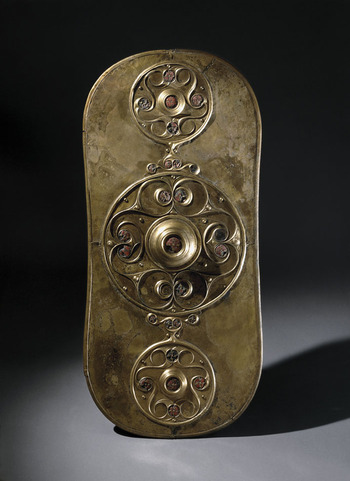


The primary plan of the Battersea Shield (fig 1), together with the deployment of its ornament, can be understood in other than the customary impressionistic terms. By attending to its mensural details – and particularly the relations between them – we can recognize its shaping and layout as a simple and elegant construction executed with dividers and straight-edge (the design tools of the time).
The Battersea Shield. Photograph: © Trustees of the British Museum

Iteration of measures and shapes, and repeated use of an elementary ratio inherent in the shield’s simple geometric form, are linked elements of the plan, as are repetition of the shape in the three circles, repetition of measure in the two equal-sized roundels above and below and repetition in their distances from the central roundel.Footnote 1
Repetition by simple copying
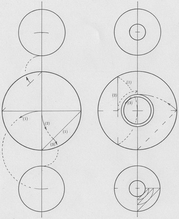
Another repetition, not easily recognizable by eye, is the measure of the diameter of the central roundel being identical to the measures from the centre of the large roundel to the centres of the two smaller ones; put another way, the radius of the large circle is equal to the measure from its perimeter to the centres of the small ones.Footnote 2 A simple way to achieve this in the layout of the plan is to draw a circle for the large roundel, as in fig 2A, and run a line through its centre – a vertical, or spinal axis for the shield; then, from either of the points of intersection between this bisecting line and the circle, copy the radius of the circle along that line to mark points to serve as the centres of the smaller roundels (1, on the left).
Constructing the plan of the Battersea Shield (beginning). Drawing: author

Linking by geometric ratio requires a second line to be taken through the centre at right angles to the first one – horizontal in this design – so that the large roundel is now divided into equal quadrants (the two lines will also be used in devising and orienting the curvilinear ornaments enclosed within the large circle). Now draw the chord of a quadrant (1, on the right) and mark off the length of a radius along it (2); the key ratio will be that of chord to radius of a quadrant of a circle (in modern notation √2:1). Then copy the remaining length of the chord below the circle to mark a point along the spinal axis (3). This sets a point on the circumference for the smaller roundel, the centre of which has already been set. Using these measures, the two smaller circles can be drawn above and below.
The two new circles will have the following mensural relations to the large central one. The distance between the perimeters of the large and small circles is √2–1 (the length remaining from manoeuvres 1, 2 in fig 2A (on the right), copied along the vertical axis). And because the distance from the centre of the large roundel to the centre of the smaller roundel is equal to two radii of the large one, the smaller radius will be 2–√2. Stead gives the diameter of the large circle (‘Panel A’) as 286–90mm, the diameter of the smaller circles (‘Panel B’ and `Panel C’) as 168–9mm and 169–71mm respectively. Taking 288mm as the median measure for the large circle, this computation (2–√2) predicts 169mm as the diameters of the two other circles. The match between mathematical model and actual artefact could hardly be closer. Entailed is this as well: that the radius of a small roundel in relation to the interval separating the large and small roundels is √2:1. What appears as tautology in this kind of notation is the basis of the shield’s patterning, by the repetition of the measures and the ratio of the measures in the physical form of the design.
Supposing the hypothetical schema being developed here is valid, what further elements in the shield’s design might it account for? At the centre of the large central circle is a boss prominent for its undecorated face – accented by the sunken ‘enamel’ roundel within it, and by its projection from the main surface.Footnote 3 It is a piece prepared separately from the flange that surrounds it. The diameter of the boss in relation to that of the large circle is another elemental function of √2. It is essentially one-half of the measure of the chord of a quadrant of the overall circle, or  ([(√2)/2]); see fig 2B on the left for the graphic computation (1, 2, 3). Again, using 288mm as the median diameter of the circle, the computation predicts the boss diameter to be 102mm; Stead gives the actual diameter of the boss as 101–3mm. Here is another match of model and artefact – schema and hardware – that could hardly be closer.
Further, the boss in the central circle is surrounded by a ring, so that the central element of the design appears larger than the boss alone. In fact, with the ring, the size of the central ornament is yet another function of √2, specifically √2–1 in relation to the flat surface within the circle. Graphic computation of this is shown in fig 2B (on the right, middle).
At the centre of each of the flanking circles is a boss-like circle, similarly rising proud of the surface and containing a central decorative ‘enamel’ element.Footnote 4 Their sizes in both instances are in the same ratio to their enclosing circles as the large boss is to its enclosing circle; fig 2B, bottom, shows an alternative procedure for plotting this ratio. In both cases, as with the larger roundel when the ring of the boss is observed, the schematic plan is accurate if the measurements are taken at the inner periphery of the enclosing circles. This is a shift from the points of measurement for placing and sizing the enclosing circles. It appears that commodulation of measures was devised separately for the internal disposition of these bosses, and for aggregating the three main circles. That is, the procedure in devising the scheme for the ornament of the shield seems to have had two separate stages – one for setting overall sizes and intervals, the other for internal proportions within each roundel – even while they employ a common geometric constant in constructing their configurations.
All the elements of the shield described thus far show a thorough and consistent match with the abstract plan. In other respects the scheme and the artefact have small differences. All of them, however, correlate with irregularities in working the three circular elements, and in mounting them on the bronze sheets that covered the shield.Footnote 5 For example, there are slight differences in the diameter measures of the two flanking roundels, and more differences in their appendages that touch the central roundel.Footnote 6 Also, the three roundels are slightly irregular in their alignment; a straight-edge (or taut string) over their centres would show this or, for that matter, it can be observed simply by observing the spinal axis at a steep slant.Footnote 7 When the schematic plan is overlaid on a photograph, these irregularities will appear as local deviations, which average out, so to speak, without modifying the basic scheme proposed here for the ornament and its deployment on the Battersea Shield.
What about the form of the shield itself? This is a modification, or variant, of the generally customary shape – ‘subrectangular’ – and it is ‘waisted’. While creating the forms of the separate roundels, and their placement in combination, answers to a coherent scheme of geometrical design in ways that have been demonstrated, that scheme was clearly not deployed in shaping the shield. The process of designing the base shield seems instead to have been quite the opposite: an improvised adaptation of a generic defensive weapon-shape to the ornament already planned or prepared for it.
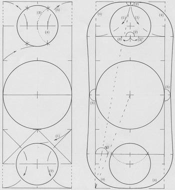
The geometric schema for the ornamental roundels (fig 2) reflected only the longitudinal relations among them and within them. In considering the shield’s size and configuration it is necessary to analyse relations among the elements, which include width as well as length. This requires shifting from the one-axis longitudinal scheme to one that computes measures of width and length together. For this, the easiest way to proceed is to lay down two squares sharing one side, the measure of each square being that of the diameter (or two radii) of the central roundel, as in fig 3. In fig 3A, it will be noted, an alternate method of setting the size of the smaller roundels is represented by copying the length of a chord of a quadrant of the larger roundel (1). In any case, all the relative dimensions represented in fig 2 will be unchanged.
Constructing the plan of the Battersea Shield (concluding). Drawing: author

The shield’s shape can be derived in a few further manoeuvres in coherent geometry with dividers and a straight-edge. First to be set is the height of the shield; entailed in this will be the basis for constructing the maximum width of the shield and for plotting the curvatures at the four corners. One method (illustrated in the lower section of fig 3A) is to extend the vertical measure of the underlying adjacent squares by half of √2 of their basic measure; that is, to the measure 2 of the joined squares, add half the diagonal measure of a quadrant of a square (2), yielding 2+[(√2)/2]. If the median measure 288mm of the central roundel is used as the basis of computation, it predicts 779.5mm overall height; the dimension reported by Stead is 777mm, which is different by about three thousandths. Another geometric procedure that will produce the same dimension is shown in fig 3A (top portion). It proceeds from the smaller roundels, beginning with finding (by construction) half its radial measure (3, 4), and then uses the complementary lateral measure to set the extension beyond the double squares (5).Footnote 8
Location of the maximum width of the shield (occurring twice) can be set as in fig 3B, by subtracting half the basic measure from the full extension of the shield, at either end. That is, the radius measure of the central circle is copied (1) to mark points along the sides of the paired squares from top and bottom, respectively; a line connecting corresponding pairs of points will mark the axis of the maximum width. An alternate method mirrors the method in fig 3A (top), to set the shield height, as illustrated in fig 3B (lower part).
The maximum width can be derived from the two maximum vertical measures – those of ornament and of the shield backing. By as much as the shield length exceeds the length of the aggregate of ornament, by double that much the maximum shield width exceeds the maximum width of the ornament (see fig 3B). In short, copy the difference between the two heights (2, 2): the spread of (2) represents the combination of lengths between ornament and edge at top and bottom together. Double it (3, 3), to mark points on either side of the centre line, along the maximum-width line. Then, with compass opened at the radius measure of the large roundel (half the measure of the underlying squares), place the fixed point in turn at the points last marked, and describe quarter-circles (4) for the corners of the shield’s outline. Slight smoothing toward the spine is then required.
The verbal narrative of construction is lengthy; the graphic manoeuvres in the drawing may be easier to follow. Or the operations can be abstracted in this way: the height of the shield is 2+[(√2)/2] in relation to the diameter of the central roundel; the height of the ornamented roundels as laid out is 2+(1–(√2–1)).Footnote 9 When the computation is carried out numerically, it predicts a maximum width of 358mm using the median 288mm of the central roundel as the ‘given’; the measure given by Stead is 359mm – within about three-thousandths.
Remaining is the ‘waist’ of the shield, the minimum width, occurring at its mid-line. Two different developments based on the scheme laid out thus far will replicate this mid-section dimension with equal degrees of accuracy. The one that is fully consonant with the preceding derivation goes as follows. It also incorporates the relative height of the shield’s base, which was 2+[(√2)/2] in relation to the diameter of the central roundel (which can also be expressed as [(4+√2)/2]), but employs its inverse. That inverse is then divided by 2, and added to the width of the underlying form.Footnote 10 In effect, it is the contrary of the derivation for the maximum width, using the inverse of the shield’s relative height, and dividing rather than multiplying by 2. A possible derivation is shown in fig 3B (5).Footnote 11 When the computation is carried out numerically, it predicts the minimum width for the waist to be 341mm; the measure given by Stead is 341mm.
Description and illustration of an alternate development method will be omitted here. The computation, briefly, is [(√3−1)/4] = 0.1830. Add that to 1, giving 1.1830. Multiply by the basic measure 288mm to get the measure 341mm. Either method comes to less than one thousandth of the reported dimension (which was not offered as accurate to that extent).
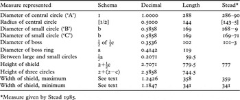
A summary of the dimensions appears in Table 1. Interestingly, the whole design can be seen as a notable result from combining 1 and 1. When laid out at a straight angle they yield the measure 2 end to end. Laid out at a right angle they yield the measure √2 end to end (to be called c). From those derive √2−1 (to be called a), and 2–√2 (to be called b); 1–a is also b. The given measure (=1) for the schema is the diameter of the central roundel; for computation of lengths based on the schema the median measure for that roundel, 288mm, is used.

The full coherent geometry of so many of the best subsequent Insular designs typically developed through the derivation of the inner shapes from the outer shape – cross, circle, rectangle and even trapezoid. And often it was perfect, in the sense that all its primary lines and areas were linked by a geometric constant which informs the outer shape, in a harmony achieved by continuous and direct derivation. And that entailed a consistent method of measuring. It is in these two respects that the Battersea Shield contrasts with objects formed in the later Insular designs, even while employing geometric planning and decorative motifs so much like those of the later tradition.Footnote 12