


NOMENCLATURE
- CT
-
main rotor thrust coefficient
- C Mx
-
main rotor aerodynamic rolling moment coefficient
- C My
-
main rotor aerodynamic pitch moment coefficient
- Ixx , Iyy , Izz , Ixz
-
mass moment of inertia of helicopter (
 $\text{kg.m}^2$
)
- L, M, N
-
net moments at helicopter centre of gravity about x, y and z axes (N.m)
- mh
-
mass of the helicopter (kg)
- p,q, r
-
fuselage angular velocity components about x, y and z axes (rad/s)
-
$\bar{r}$
-
non-dimensional radial location
- u, v ,w
-
fuselage translational velocity components along x, y and z directions (m/s)
- X, Y, Z
-
net forces at helicopter centre of gravity along x, y and z directions (N)
- α
-
angle-of-attack of tip path plane; positive nose down
- β k
-
kth blade flap angle - rotating frame
- β M , β−M
-
collective and alternating flap angle - non-rotating frame
- β1c , β1s
-
cyclic flap angles - non-rotating frame
- χ
-
wake skew angle
- λ D
-
inflow from Drees inflow model
- λ DI
-
inflow from dynamic inflow model
- λ UI
-
uniform inflow
- λ0
-
mean inflow ratio
- λ i
-
induced inflow ratio
- λ1c , λ1s
-
lateral/longitudinal skew inflow ratio
- μ
-
advance ratio
- θ0, θ1c , θ1s
-
main rotor collective and cyclic pitch angles
- θ tr
-
tail rotor collective pitch angle
- ψ
-
blade azimuth location
- Φ
-
roll attitude
- Θ
-
pitch attitude


Greek Symbol
1.0 INTRODUCTION
In modern day rotorcraft design, the handling qualities and mission effectiveness of the rotorcraft must be evaluated in the preliminary design stage. Most of the handling quality parameters specified in MIL-H-8501(1) and ADS-33E(Aeronautical Design Standard)(2) are defined based on the control response characteristics of the rotorcraft. MIL-H-8501 specifies the response characteristics of a rotorcraft, in terms of control power, force and moment gradient to the control stick input. ADS-33E(2) provides mission-oriented specifications. It defines operational missions and Mission-Task-Elements, response characteristics, agility parameters, operational environment, levels of handling qualities, flight envelopes, configurations, loadings and rotorcraft failure modes. ADS-33E handling quality ratings are defined based on Cooper-Harper(Reference Cooper and Harper3) ratings. Control response is the vehicle’s open-loop response to a given control stick movement. Reliable and reasonably simplified flight dynamic models are needed to compute the control response and subsequently the handling qualities of the rotorcraft.
The basic rotorcraft flight dynamic model is a combination of mathematical models representing main rotor, tail rotor, fuselage, horizontal stabiliser and vertical stabiliser. Engine, actuator and transmission dynamics models are also included in a few flight dynamic models. Mostly, the main rotor modelling is given more importance while tail rotor, fuselage and empennage are modelled in as simple a manner as possible. Flight dynamics of a rotorcraft can be modelled in several ways, starting from a simple flight dynamic model (rigid flap assumption for rotor blade) to a more sophisticated elastic blade comprehensive model. The comprehensive aeroelastic analysis is generally used to predict the vibratory loads, blade response and also flight dynamics.
Simplified models can be used for flight dynamics analysis and controller design. The linear controller needs a linearised model which can be derived numerically or experimentally. Kalketka(Reference Kalketka4) used the system identification approach to obtain the linearised model for BO 105 and compared the different identified linear models. Pallett et al(Reference Pallett and Ahmad5) developed a dynamic model of a miniature helicopter in hovering flight. Identification procedures are also described by them and the model was used to design several linear control laws and a neural network controller. Kim et al(Reference Kim and Tilbury6) developed a mathematical model for a model scale helicopter robot, with emphasis on the dynamics of the flybar. Cunha et al(Reference Cunha and Silvestrey7) developed a flight dynamic model that was specially tailored for mini helicopters. Sakthivel(Reference Sakthivel8) developed a flight dynamic model for a mini helicopter with Bell-Hiller stabiliser bar and analysed the trim, stability and control response.
While evaluating the control response behaviour of the helicopter, the importance of the following three points are noted. They are: (i) inflow modelling, (ii) the magnitude of perturbation step size in the extraction of the linearised model, and (iii) the integration step size in the evaluation of non-linear control response of a vehicle. There are many inflow models available in the literature and they can be categorised as time invariant (constant) and time varying (dynamic) inflow models. Chen(Reference Chen9) surveyed several non-uniform inflow models and concluded that the three-state dynamic inflow model works well with several sets of test data. In the present study, a new inflow model is proposed and it is denoted as updated Drees model. In this model, the inflow is evaluated at every time instant knowing the value of instantaneous rotor thrust. It is observed that the proposed updated Drees model predicts the control response fairly close to the three-state dynamic inflow model and also flight test data.
In the extraction of the linearised model, it is observed that the magnitude of perturbation step size has a strong influence on the stability and control derivatives, thereby affecting the eigenvalues and control response. In the non-linear control response studies, the integration timestep influences rotor inflow, blade response and also the vehicle response. The results of the non-linear control response studies indicate that convergence is obtained for a timestep corresponding to an azimuth angle of 0.2°. Even though the present study is not related to rotor CFD, it is interesting to note(Reference Min and Sankar10) that a timestep corresponding to 0.05° azimuth gives the best accuracy in the rotor CFD computations.
The objectives of this study are as follows:
-
• Develop a relatively simple flight dynamic model by extending the model developed in Ref. (8), which can be used to analyse the trim, stability and control response under various manoeuvring conditions and evaluate handling quality parameters.
-
• Study the influence of perturbation step size on the eigenvalues and the control response of a linearised model to a given input.
-
• Analyse the effect of timestep in evaluating the control response using the complete set of non-linear flight dynamic equations.
-
• Propose a new “Updated Drees inflow model” in evaluating trim, stability and control response. Compare the control responses obtained using the updated Drees inflow model and the responses evaluated using the dynamic inflow model.
-
• Compare the non-linear control response obtained using a simple model, the responses evaluated using the Comprehensive Aeroelastic Flight Dynamic Analysis of Rotorcraft (CAFDAR) and the flight data. CAFDAR(Reference Rohin Kumar and Venkatesan11,Reference Rohin Kumar and Venkatesan12) is a comprehensive model developed at the Helicopter laboratory, IIT Kanpur, India. It includes a generic finite element model for rotor blade structural dynamic analysis, which can be used to analyse various rotor systems such as articulated rotor, hingeless rotor and bearingless rotor. The aerodynamic model includes reverse flow, compressibility effects, dynamic stall(Reference Laxman and Venkatesan13) and dynamic wake models with several states.
2.0 FLIGHT DYNAMIC MODEL
The present flight dynamic model is developed using individual blades so that the non-linear transient response of the vehicle as well as the linearised system control response can be analysed using one general formulation. The following simplifications and assumptions are made in the modelling.
-
• Rotor blades are assumed to be rigid with an equivalent hinge offset having a root spring.
-
• Only blade flapping is considered. Lead-lag and torsion modes are ignored.
-
• Blades are rectangular with linear twist.
-
• Linear lift curve slope is assumed.
-
• Reverse flow effects are neglected.
-
• Stall and compressibility effects are not considered.
-
• Fuselage is assumed as a rigid body.
-
• Model includes tail rotor, horizontal and vertical fin.
2.1 Inflow Models
Four different inflow models are used in this study for comparative purposes. They are as follows:
-
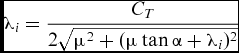
Uniform Inflow: The total inflow (λ UI ) through the rotor disc is assumed to be constant. Induced inflow (λ i ) is calculated by using average rotor thrust over one revolution
(1)where
$$\begin{equation}
\lambda _{UI} = \mu \tan \alpha +\lambda _i,
\end{equation}$$
(2)
$$\begin{equation}
\lambda _i = \frac{C_T}{2\sqrt{\mu ^2+(\mu \tan \alpha +\lambda _i)^2}}
\end{equation}$$
-
Drees Inflow: The rotor inflow (λ D ) is a function of both azimuth and radial location of the blade. In this model, induced inflow (λ i ) is calculated based on average rotor thrust over one revolution, using Equation (2).
(3)where
$$\begin{equation}
\lambda _{D}\left(\bar{r},\psi \right) = \mu \tan \alpha +\lambda _i\left(1+k_x\bar{r}\sin \psi +k_y\bar{r}\cos \psi \right),
\end{equation}$$
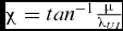
where χ is a wake skew angle and it is defined as
$$\begin{eqnarray*}
k_x &=& -2\mu \\
k_y &=& \frac{4}{3}\left[\left(1-1.8\mu ^2\right)\csc \chi -\cot \chi \right],
\end{eqnarray*}$$
$\chi = tan^{-1}\frac{\mu }{\lambda _{UI}}$
.
-
Updated Drees Inflow: The updated Drees model, which is proposed in this study, is similar to the Drees inflow model. In this model, induced inflow (λ i ) is calculated at every timestep using instantaneous rotor thrust using the expression given in Equation (2).
-
Dynamic Inflow: The inflow is a function of azimuth, radial station and time. The current study uses three-state dynamic inflow models(Reference Pitt and Peters14). The model consists of three first-order differential equations, which is integrated in time domain. The equations are given as
(4)
$$\begin{equation}
\lambda _{DI}\left(\bar{r},\psi \right) = \mu \tan \alpha +\lambda _1+\lambda _{1s}\bar{r}\sin \psi +\lambda _{1c}\bar{r}\cos \psi
\end{equation}$$
(5)The matrices M, V and L are given in the Appendix.
$$\begin{eqnarray}
\left[M\right]\left\lbrace \arraycolsep5pt\begin{array}{c}\dot{\lambda _1} \\
\dot{\lambda _{1s}} \\
\dot{\lambda _{1c}} \end{array}\right\rbrace + \left[V\right] \left[L\right]^{-1}\left\lbrace \arraycolsep5pt\begin{array}{c}\lambda _1 \\
\lambda _{1s} \\
\lambda _{1c} \end{array}\right\rbrace = \left\lbrace \arraycolsep5pt\begin{array}{c}C_T \\
C_{M_x} \\
C_{M_y} \end{array}\right\rbrace
\end{eqnarray}$$





2.2 Load Calculation
The main rotor loads consist of aerodynamic loads and inertial loads. The sectional forces and moments are integrated over the radius of the rotor blades. Integrated loads from all the blades are added and transformed to hub axes. Hub forces are calculated at every azimuth location and averaged over one revolution to obtain mean hub loads. But for tail rotor, only thrust force is taken into account and other loads are neglected. The inflow for the tail rotor is considered to be uniform. Fuselage drag force is evaluated using an equivalent flat plate area. The empennage consists of a vertical stabiliser and a horizontal stabiliser. Only normal aerodynamic forces from these surfaces are considered. All the forces and moments are then transferred to a helicopter’s centre of gravity. Using the forces (X, Y and Z) and moments (L, M and N) at the helicopter’s centre of gravity, flight dynamic equations for a general manoeuvre are written as follows(Reference Padfield15).
Force Equations:
 $$\begin{equation}
\dot{u} = -\left(wq- vr\right)+\frac{X}{m_{h}}-g\sin \Theta
\end{equation}$$
 $$\begin{equation}
\dot{v} = -\left(ur- wp\right)+\frac{Y}{m_{h}}+g\cos \Theta \sin \Phi
\end{equation}$$
 $$\begin{equation}
\dot{w} = -\left(vp- uq\right)+\frac{Z}{m_{h}}+g\cos \Theta \cos \Phi
\end{equation}$$
Moment Equations:
 $$\begin{equation}
I_{xx}\dot{p} = \left(I_{yy} -I_{zz}\right)rq+I_{xz}\left(\dot{r}+pq\right)+L
\end{equation}$$
 $$\begin{equation}
I_{yy}\dot{q} = \left(I_{zz} -I_{xx}\right)rp+I_{xz}\left(r^{2}-p^{2}\right)+M
\end{equation}$$
 $$\begin{equation}
I_{zz}\dot{r} = \left(I_{xx} -I_{yy}\right)pq+I_{xz}\left(\dot{p}-rq\right)+N
\end{equation}$$
Kinematic relations:
 $$\begin{equation}
\dot{\Theta } = q\cos \Phi -r\sin \Phi
\end{equation}$$
 $$\begin{equation}
\dot{\Phi } = p+q\sin \Phi \tan \Theta +r\cos \Phi \tan \Theta
\end{equation}$$
3.0 SOLUTION TECHNIQUE
3.1 Trim Calculation
The flight dynamic Equations (6)–(8) can be expressed in the following compact form.
 $$\begin{equation}
\dot{x} = f\left(x,U,t\right)
\end{equation}$$
In the above equation, x is a state vector consisting of the states (u, v, w, p, q, r, Θ and Φ) and U is the control vector representing the main rotor and tail rotor control angles (θ0, θ1c , θ1s and θ tr ). For a general steady-state flight condition, the rate of the states (x) are set equal to zero. The system of Equations (9) are solved simultaneously for trim control angles, pitch (Θ) and roll (Φ) attitudes. Figure 1 shows the solution procedure to obtain trim, stability and control derivatives. Trim solver consists of an inner loop and an outer loop. Inner loop consists of either flap dynamics or both flap and inflow dynamics, depending on the inflow model. Functioning of inner loop for different inflow models is described in the following section. After convergence of inner loop, the blade loads as well as hub loads are evaluated at 72 azimuthal stations (interval of 5° azimuth). The hub loads are averaged over one revolution to obtain the mean hub loads and transferred to the outer loop. The outer loop corresponds to the trim solver, and the Newton Raphson method is used to solve the trim equations.
-
Time invariant inflow models: Uniform inflow and Drees inflow models are called as time invariant inflow models. The inner loop contains only the flap dynamics and the induced inflow is evaluated in the outer loop. In the inner loop, the induced inflow (λ i ) is treated as a constant and only the convergence of flap dynamics along the rotor blade loads is established. Using the mean value of the aerodynamic thrust, in the outer loop, the induced inflow is updated. In addition, other trim variables (control and attitude angles) are also updated. This procedure is continued till the convergence of trim variables and inflow.
-
Time varying inflow: Updated Drees inflow and dynamic inflow models are denoted as time varying inflow models. The inner loop contains both inflow and flap dynamics. In the inner loop, for the updated Drees model, the induced inflow (λ i ) is calculated (Equation (2)) at every azimuth step using instantaneous total thrust. Equation (2) is solved by algebraic equation solver incorporating the Newton-Raphson numerical scheme. The previous timestep-induced inflow value is chosen as an initial condition for this solver. Using the converged induced inflow obtained from the Newton-Raphson method, the wake skew angle (χ) and other inflow components (λ1c , λ1s ) are calculated and updated for the next timestep.
Figure 1.Flow chart for Trim and Stability.
For the dynamic inflow model, inflow components (λ i , λ1c and λ1s ) are calculated at every azimuth step using instantaneous total thrust, roll moment and pitching moment. The differential equation solver is used in dynamic inflow. Convergence of both inflow and flap response is ensured in the inner loop. It is to be noted that in this case, the inflow components are time varying about steady mean values.
-
Convergence criterion for inner loop: The flap and inflow responses are calculated for every 5° azimuth location (72 points per revolution). Two consecutive rotor revolution data are stored in two different vectors (say, X1 and X2). The convergence is based on minimising the norm of the difference between those two vectors (min ‖X1 − X2‖). The inner loop normally converges within 10–15 rotor revolutions.

3.2 Stability Derivatives Evaluation
The trim parameters are given to the stability module to calculate the stability and control derivatives by using the forward difference scheme. Trim loads are calculated directly from the trim parameters. The state vector and the control vector are perturbed from the trim state one variable at a time to obtain the perturbed loads acting at the Center of gravity (CG) of the helicopter. Perturbed loads are calculated after the convergence of the inner loop (inflow and flap) for all state variable and control angle perturbations. Since steady-state rotor flap response and inflow values are obtained for every perturbation, the coupling between low-frequency fixed frame flapping and the body Degrees of freedom (DOF) is ignored. Perturbation step size depends on the nature of states. The stability and control matrices are formed from these derivatives. The linearised system dynamics about the trim condition is given by the following equation.
 $$\begin{equation}
\dot{x} = Ax+Bu,
\end{equation}$$
where A is the system matrix and B is the control matrix. Eigenvalues of the system matrix are used to analyse the stability characteristics of the rotorcraft. Using Equation (10), the linearised system response of the vehicle to a given control input is obtained.
3.3 Non-linear Response Calculation
In non-linear response analysis, the system of Equations (9) are integrated in time domain. The procedure for control response calculation is shown in Fig. 2. For the cases of uniform inflow and Drees inflow models, inflow value at trim condition is used throughout the control response calculation, and the inflow value is not updated in these two cases.
Flow chart for non-linear control response.

In updated Drees inflow model, the algebraic equation solver is used (as indicated by the arrow with the dashed line in Fig. 2) to evaluate the inflow at every timestep. In the case of dynamic inflow, the differential equation solver is used (as indicated by the arrow with continuous line in Fig. 2) to update the inflow at every timestep. The trim parameters (states, flap and inflow) are considered as initial conditions because the system is perturbed from the trim position. Using the states of the system, flap and inflow at the ith timestep, the loads are calculated at the ith timestep. Using the loads at the ith step, the states of the vehicle, the blade flap and rotor inflow are calculated at the (i + 1)th timestep.
4.0 RESULTS AND DISCUSSION
The results of the study are presented in two parts. In the first part, the effects of perturbation step size (forward difference scheme) on the formulation of linearised stability and control matrices are analysed. In addition, the effect of the integration timestep on the non-linear control response is also addressed. The second part deals with analysing the effect of inflow model on the control response of the non-linear model.
4.1 Effect of Perturbation Step Size on Linearised Model
In the linearised stability and control response analysis, the magnitude of the perturbation in the state and control variable influences the stability and control derivatives. In Ref. (15), it is suggested to use a perturbation step size of 1m/s in velocities, 0.1rad/s in angular rates and 0.1rad in attitudes and control angles to obtain the linearised model. These perturbation quantities are taken as baseline perturbation values. The six sets of perturbation quantities used in this study are given as follows.
-
• Baseline (1m/s, 0.1rad/s and 0.1rad)
-
• 0.5 × Baseline
-
• 0.1 × Baseline
-
• 0.01 × Baseline
-
• 0.001 × Baseline
-
• 0.0001 × Baseline
Using these perturbation sets, the stability and control matrices are obtained separately. The Drees inflow model is used for this analysis. The responses are generated under the hovering condition for 1° collective step input. All the relevant data are given in Tables 1 and 2. The eigenvalues of these system matrices are given in Table 3. It is observed that the vehicle exhibits two oscillatory modes and four non-oscillatory modes. The first eigenvalue is −10.67rad/s, which is presumably the roll damping mode. From Table 3, it is noted that the four non-oscillatory modes are not influenced significantly by the perturbation step size. However, in the oscillatory modes, modal damping seems to be influenced more than the frequency by the perturbation step size. It is observed that the eigenvalues corresponding to 0.1 times the baseline perturbation and 0.01 times the baseline perturbation are the same. It may be noted that the eigenvalue analysis only deals with the effect of the perturbation step size on the stability matrix, whereas the control response analysis reveals the influence of the perturbation step size on both stability and control matrices. Using the stability and control matrices, the control response is obtained and compared in Fig. 3. In the generation of control response, the timestep used is 0.00265sec (corresponding to a 5° azimuth). The control response results are not affected, even if the integration time is reduced to 1/10 of this value. From Fig. 3, it is observed that the influence of perturbation step size on the control response is significant. The control response seems to converge for all the step sizes below 0.1 times the baseline perturbation in all the vehicle states. From both eigenvalue and control response analysis, 0.1 times the baseline perturbation can be taken as the suitable perturbation step size.
Main rotor and tail rotor

Fuselage and empennage

Effect of size of the perturbation on the eigenvalues of the system (Baseline: Velocity:- 1m/s, Rates:- 0.1rad/s, Attitude:- 0.1rad)

Effect of magnitude of perturbation size on the control response for 1°
collective step input in hover.

4.2 Effect of Integration Timestep on Non-linear Model Response
Under hovering flight conditions, non-linear control response is evaluated for 1° collective step input. The dynamic inflow model is used in the non-linear response analysis. All the relevant data are given in Tables 1 and 2. Five different integration timesteps are used. These integration timesteps correspond to azimuth angle increment of 5°, 3°, 1°, 0.5° and 0.2°. The response corresponding to these integration timesteps are shown in Fig. 4. It can be seen that the integration timestep influences the responses of lateral (v) and longitudinal velocities (u), pitch rate (q) and roll rate (p) and corresponding pitch(Θ) and roll(Φ) angles. As the timestep decreases, the difference between the responses seems to decrease. The vertical velocity and yaw rate are least influenced by the integration timestep. The variation of inflow states corresponding to these integration timesteps are shown in Fig. 5. Mean inflow λ0 (which is equal to μtanα + λ1) is not influenced by the timestep and this is reflected in the vertical velocity and yaw rate response, as shown in Fig. 4. The lateral and longitudinal inflow components (λ1c and λ1s ) are strongly influenced by the timestep. The variation in the these components is responsible for the observed variations in the roll rate and pitch rate responses. Flap response of a reference blade in rotating frame for different integration timesteps is shown in Fig. 6. The amplitude of the flap response is slightly influenced by the timestep. For a reduction of integration timestep from 5° to 0.2°, the amplitude of flap response has shown a very slight increase of 0.12°.
Effect of integration timestep on the non-linear control response for 1°
collective step input in hover.

Effect of integration timestep on the rotor inflow response.

Effect of integration timestep on the blade flap response of the reference blade in rotating frame.

Using the flap response of individual blades in a rotating frame and applying a multi-blade coordinate transformation, the flap response in the non-rotating frame in all rotor modes are obtained. Figure 7 shows the collective (β M ), alternating (β−M ), lateral and longitudinal cyclic flap (β1s and β1c ) response in the non-rotating frame corresponding to different timesteps ranging from 5° to 0.2°. Collective and alternating flap modes are not influenced by the integration timestep. The magnitude of the alternating mode is very small and it is of the order of 10−4°. The collective mode is a damped mode and the frequency of this mode is found to be 5.23Hz. The fixed frame low frequency cyclic flap mode is found to be 1.47Hz (from β1s , Fig. 7), which is 9.23rad/s. The lateral and longitudinal cyclic flap modes are influenced by integration timestep. The responses seem to converge for the time corresponding to a 0.2° azimuth. The observation with regard to the influence of timestep in collective and cyclic flap modes is very similar to the observations made on the mean and cyclic inflow variables as shown in Fig. 5. For the sake of clarity, the encircled regions in Fig. 7 are enlarged and are shown in Fig. 8. It is observed that the initial responses seem to be similar for all the timestep. As time evolves, the responses deviate significantly. It is observed that the difference is very small between the responses (vehicle response (Fig. 4), inflow (Fig. 5) and flap responses (Fig. 7)) corresponding to the timesteps related to the 0.5° and 0.2° azimuth increment. The timestep corresponding to the 0.5° azimuth (0.000265sec) is taken as the timestep for later studies.
Effect of integration timestep on the blade flap response in the non-rotating frame.

Initial trend of the cyclic flap response in the non-rotating frame.

4.3 Effect of Inflow Model
The results presented in this section correspond to the study on the effect of the inflow model on the flight dynamic parameters such as trim and control response of the non-linear model. The control responses are obtained for a 1° collective step input at an advance ratio of 0.05. The rotorcraft data used for this analysis are given in Tables 1 and 2.
4.3.1 Trim
The trim angles corresponding to the advance ratio of 0.05 for the four inflow models are given in Table 4. It is observed that the trim angles are the same for both the Drees and the Updated Drees model. The main rotor collective pitch angle remains almost the same for all inflow models. Lateral and longitudinal cyclic pitch angles are influenced by the choice of inflow models. Uniform inflow under-predicts the lateral and longitudinal cyclic angles. The reason for this large influence on cyclic angles is because the inflow models, other than the uniform inflow model, have lateral and longitudinal inflow components, which affect the pitching and rolling moment of the main rotor. The tail rotor collective pitch angle is not significantly influenced. However, the small variation in tail rotor collective may be attributed to the change in main rotor mean torque due to the lateral and longitudinal components of inflow. The pitch and roll attitudes are also influenced by the inflow models.
Effect of inflow models on trim angles (in degrees)

4.3.2 Non-linear model response
The non-linear control responses for a given prescribed control input for the four inflow models are compared in Fig. 9. It is observed that the responses corresponding to the uniform inflow and the Drees inflow model are very close in all the vehicle states. Whereas the responses from the updated Drees model and dynamic inflow model are close in all the states, except in pitch rate and pitch attitude. The reason for this observation in pitch rate and pitch attitude can be attributed to the rotor inflow and blade flap responses. The rotor inflow variation for all the inflow models is shown in Fig. 10. In uniform inflow and Drees inflow models, the inflow components are constants. In the updated Drees and dynamic inflow models, the inflow components vary with time. It can be seen that the dynamic inflow model and the updated Drees inflow model give fairly close response in mean inflow (λ0). In the lateral inflow component (λ1c ), a steady offset between the updated Drees inflow model and the dynamic inflow model is observed. This disagreement in lateral inflow component may be due to the difference in the functional form of the model itself. The significant difference is found in the longitudinal inflow component (λ1s ) response and it is reflected in pitch rate and pitch attitude as shown in Fig. 9.
Comparison of non-linear model responses for a 1° collective step input at μ = 0.05.

Comparison of rotor inflow response for a 1° collective step input at μ = 0.05.

In order to bring forth the applicability of the updated Drees model, the responses obtained from updated Drees inflow and dynamic inflow models are compared for additional flight conditions such as forward flight and recovery manoeuvre from steady left and right turns. Figure 11 shows the comparison of control responses obtained from updated Drees inflow and dynamic inflow models for 1° lateral cyclic step input at the advance ratios of 0.10 and 0.30. Figure 12 shows the comparison of control responses obtained from updated Drees inflow and dynamic inflow models for 1° longitudinal cyclic step input at the advance ratios of 0.10 and 0.30. From Figs 11 and 12, it is noted that the updated Drees model responses are fairly close to the responses obtained from the dynamic inflow model. The difference between the responses from updated Drees and dynamic inflow models reduces as the advance ratio increases. Figures 13 and 14 show the comparison of recovery responses obtained from updated Drees inflow and dynamic inflow models for steady left and right turns, respectively, at an advance ratio of 0.20. Recovery manoeuvres are initiated by giving a lateral cyclic step input of +5° in right turn and −5° in left turn. It is observed that the responses obtained from the updated Drees model are in good agreement with the responses obtained from the dynamic inflow model.
Control response comparison for lateral cyclic step input at advance ratios of 0.10 and 0.30.

Control response comparison for longitudinal cyclic step input at advance ratios of 0.10 and 0.30.

Control response during recovery from a steady left turn manoeuvre of a 23.4 deg/s turn rate at an advance ratio of 0.20 for a step lateral cyclic input of +5°.

Control response during recovery from a steady right turn manoeuvre of 23.4°/s turn rate at an advance ratio of 0.20 for a step lateral cyclic input of +5°.

4.4 Effect of Modelling Complexity on Control Response
The non-linear control response obtained from the simple model is compared with the response obtained using a comprehensive model (CAFDAR) and flight test (Reference Singh and Venkatesan16). Two inflow models are considered in the simple flight dynamic model. They are: the updated Drees inflow model and the three-state dynamic inflow model. CAFDAR model uses the 15 states Peter-He inflow model, the aerodynamic stall model and the elastic blade model. Eight rotating modes corresponding to four flap, two lag, one torsion and one axial are considered in the blade structural model. All the responses are obtained for an advance ratio of 0.2. The normalised roll rate and roll angle responses to a step lateral cyclic input obtained using the simple flight dynamic model and CAFDAR are compared with the flight test data in Fig. 15. The responses obtained from the simple model and CAFDAR show good correlation with flight data. Figure 16 shows the comparison of the normalised pitch rate and the pitch attitude response for a longitudinal step input. It is observed that the initial responses obtained using simple model match with CAFDAR and flight data. But the simple model response deviates as time evolves. Comprehensive model response is fairly close to the flight data in both lateral and longitudinal cases. It can be stated that the dynamic component of inflow did not seem to significantly affect the predicted response, since the updated Drees model seems to well-represent the response obtained by using CAFDAR.
Comparison of control response with flight data for lateral cyclic step input at μ = 0.20.

Comparison of control response with flight data for longitudinal cyclic step input at μ = 0.20.

5.0 CONCLUDING REMARKS
In this study, a simplified flight dynamic model has been developed to analyse the control response of a helicopter. The important observations from this study are:
-
• The influence of magnitude of perturbation quantities on the linearised model characteristics, such as eigenvalues and control response, is analysed. The suitable perturbation quantities to obtain a linearised flight dynamic model are found to be 0.1m/s in velocities, 0.01rad/s in angular rates and 0.01rad in attitudes and control angles.
-
• The effect of integration timestep on the control response using the non-linear model is studied. It is observed that the integration timestep influences the response significantly. It is found that the responses converge for a timestep of 0.000265sec (corresponding to a 0.5 azimuth) or less than that.
-
• A new updated Drees model is proposed and the applicability of this model in the flight dynamic analysis is studied. The control response obtained using the Updated Drees inflow model and dynamic inflow model are found to be in close agreement.
-
• The control response to lateral and longitudinal step input are compared with limited flight test data. The initial response of the simple flight dynamic model matches with the flight test as well as the response obtained using the comprehensive aeroelastic and flight dynamic model.
APPENDIX
A.0 Matrices used in dynamic Inflow
L-matrix:
 $$\begin{equation}
\left[L\right] = \left[\arraycolsep5pt\begin{array}{ccc}\displaystyle\frac{1}{2} & 0 & \displaystyle\frac{15\pi }{64}\tan \displaystyle\frac{\chi }{2} \\[6pt]
0 & \displaystyle\frac{-4}{1+\cos \chi } & 0 \\[6pt]
\displaystyle\frac{15\pi }{64}\tan \displaystyle\frac{\chi }{2} & 0 & \displaystyle\frac{-4\cos \chi }{1+\cos \chi } \end{array}\right]
\end{equation}$$
Velocity matrix:
 $$\begin{equation}
\left[V\right] = \left[\arraycolsep5pt\begin{array}{ccc}V_T & 0 & 0 \\[6pt]
0 & V_R & 0 \\[6pt]
0 & 0 & V_R \end{array}\right]
\end{equation}$$
 $$\begin{eqnarray*}
V_T &=& \sqrt{\mu ^2 +\lambda _{UI}^2} \\[6pt]
V_R &=& \frac{\mu ^2+\lambda _{UI}\left(\lambda _{UI}+\lambda _i\right)}{\sqrt{\mu ^2 +\lambda _{UI}^2}}
\end{eqnarray*}$$
Apparent mass matrix:
 $$\begin{equation}
\left[M\right] = \left[\arraycolsep5pt\begin{array}{ccc}\displaystyle\frac{8}{3\pi } & 0 & 0 \\[6pt]
0 & \displaystyle\frac{-16}{45\pi } & 0 \\[6pt]
0 & 0 & \displaystyle\frac{-16}{45\pi } \end{array}\right]
\end{equation}$$
ACKNOWLEDGEMENTS
The authors would like to acknowledge the Department of Science and Technology (DST), India for their financial support to this work.



