I. INTRODUCTION
Vivaldi antenna has drawn a great attention to the researcher for some special applications like microwave imaging, radar systems, and vehicular communication [Reference De Oliveira, Perotoni, Kofuji and Justo1]. Vivaldi is a good candidate for microwave imaging application due to its wideband, stable directional radiation pattern, high gain, endfire radiation, obtain resonant at a lower frequency, low profile, and low cost [Reference Alzabidi, Aldhaeebi and Elshafiey2]. The initial work concentrates on developing high gain, directive, low profile, and wide band antenna covering the frequency band 3.1–6.5 GHz for microwave breast imaging (MBI). In a study [Reference Abbak, Çayören and Akduman3], a cavity-backed Vivaldi antenna (CBVA) has been proposed for breast phantom measurement. By using CBVA, the size is reduced significantly, whereas the gain does not improve. A square dimension (75 mm × 75 mm) tapered slot Vivaldi antenna has been investigated in [Reference Wu, Ji and Fang4], where directive radiation pattern is achieved by optimizing antenna parameter, but resonant at a higher frequency not obtained. In [Reference He, Shan, Fan, Mo, Yang and Chen5], an improved Vivaldi antenna with planner directors in front of the aperture and transverse slot has been fabricated to increase the gain and directivity of antenna; whereas, the dimension of antenna dramatically increases (110 × 260 mm) and there is some band gap in the measured voltage standing wave ratio (VSWR). An antipodal Vivaldi antenna for microwave imaging has reported in [Reference Pandey, Verma and Meshram6] with very compact size by metallic bending feed line structure and the modulated Gaussian slot. It has nice fractional bandwidth and wider operating frequency, but the gain and reflection efficiency are not so good.
A planar antenna array that includes 12 corrugated tapered slot elements [Reference Mohammed, Abbosh and Sharpe7] satisfies low profile and moderate gain at the expense of significant length.
In this study, a modified, novel, and high-performance Vivaldi antenna is presented featuring modified radiating fins called Side Slotted Vivaldi Antenna (SSVA). Several slots are etched away on the radiating fins to enhance the electrical length, gain, and produce stronger directive radiation. Simulated and measured results of different frequencies for reflection coefficient, gain, efficiency, radiation pattern, transmitted and received pulse for a dual mode of the antenna with fidelity factor are presented to validate the usefulness of proposed antenna for microwave imaging system. It is important to note that the proposed prototype structure is simpler and smaller than those studied in [Reference De Oliveira, Perotoni, Kofuji and Justo1–Reference Pandey, Verma and Meshram6].
II. SSVA DESIGN AND OPTIMIZATION
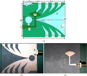
The geometric layout of proposed SSVA is shown in Fig. 1(a). This structural modification of radiating fins, stub, and cavity assist in achieving the compactness and electrical dimension of the antenna with high gain. The antenna dimension is 45 mm × 53 mm fabricated on Rogers RT/Druid 5870 substrates with dielectric constant of 2.33 and loss tangent 0.0012. The radiation properties of SSVA are determined by a set of exponential curves, tapered rate, cavity structure, slot line, back wall offset, stub arrangement, feeding position, and the structure of radiating fins.
(a) SSVA geometric layout, (b) fabricated prototype (front), (c) fabricated prototype (back).

In SSVA, all these parameters are adjusted and radiating fins are modified by etching several slots. The irregular slot is made to increase the electrical length and achieve higher gain. The main radiating lobe of SSVA is its flare, with height Hf = 43 mm and length Lf = 40 mm with tapered rate R = 0.05 (factor determining the opening rate of the flare) of the inner exponential profile. The exponential curve that employs Vivaldi antenna is defined as:
 $$x = \pm C_1e^{Rz} + C_2,$$
 $${\rm where\;} \;C_1 = \displaystyle{{x_2 - x_1} \over {(e^{Rz_2} - e^{Rz_1})}}\quad {\rm and}\quad \; \; C_2 = \displaystyle{{x_1e^{Rz_2} - x_2e^{Rz_1}} \over {(e^{Rz_2} - e^{Rz_1})}}.$$
The points (x1, z1) and (x2, z2) are the peak point P2 and the bottom points P1 of the exponential curve. The cavity diameter (Cd) of resonant cavity plays a vital role in return loss characteristic of the proposed antenna. In the proposed antenna, cavity diameter Cd of resonant cavity is kept at 9 mm, to maintain the lower end S 11 ≤ −10 dB limitation at 2.7 GHz. The cavity is adjusted with the equation:
 $$C_a = 0.5C_d - 0.5C_d(\cos \theta ),$$
 $${\rm \; where}\;\theta = \sin \left( {\displaystyle{{S_w} \over {C_d}}} \right).$$
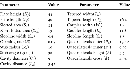
Table 1 presents the value of antenna parameters. The ratio of slotted (Sa) and non-slotted (Sna) area is 62:38. On both sides, there are three identical slots (S1, S2, S3) and on upper side there is an extra slot S4. The reason of this extra slot is to increase the efficiency, which increases the efficiency about 3%. In the x-axis, the gap of each slot is 4 mm, and in the y-axis, it is from 4.5 to 7.5 mm (S 1, S 2, S 3, S 4) with single increment. The inner surface is increased by a factor of 2 mm. An identical quadrilateral has taken on the upper back of the radiating fins. The microstrip coupler (Lc) is situated between the microstrip tapper and stub. A 50 Ω SMA connector with 2.08 dielectric constant and 0.000462 S/m conductivity is used to feed the antenna connected to microstrip tapered line.
Structure design parameters of SSVA (in mm).

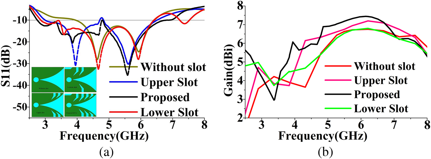
The effects of slots on the radiating fins to the reflection coefficient and gain are shown in Fig. 2. Without slot S 11 is 3.9–6.4 GHz, with lower slot S 11 is 2.9–6.4 GHz, with the upper slot S 11 is 3.0–6.5 GHz, and for all the slots (proposed), S 11 is 2.7–7 GHz with reflection coefficient <−10 dB. Without slot and with the lower slot, the peak gain is about 6.7 dBi; with the upper slot, the peak gain is 7.1 dBi; but with all slots (proposed), the peak gain is 7.5 dBi.
Effect of the slot on the radiating fins to the (a) S 11 and (b) gain.
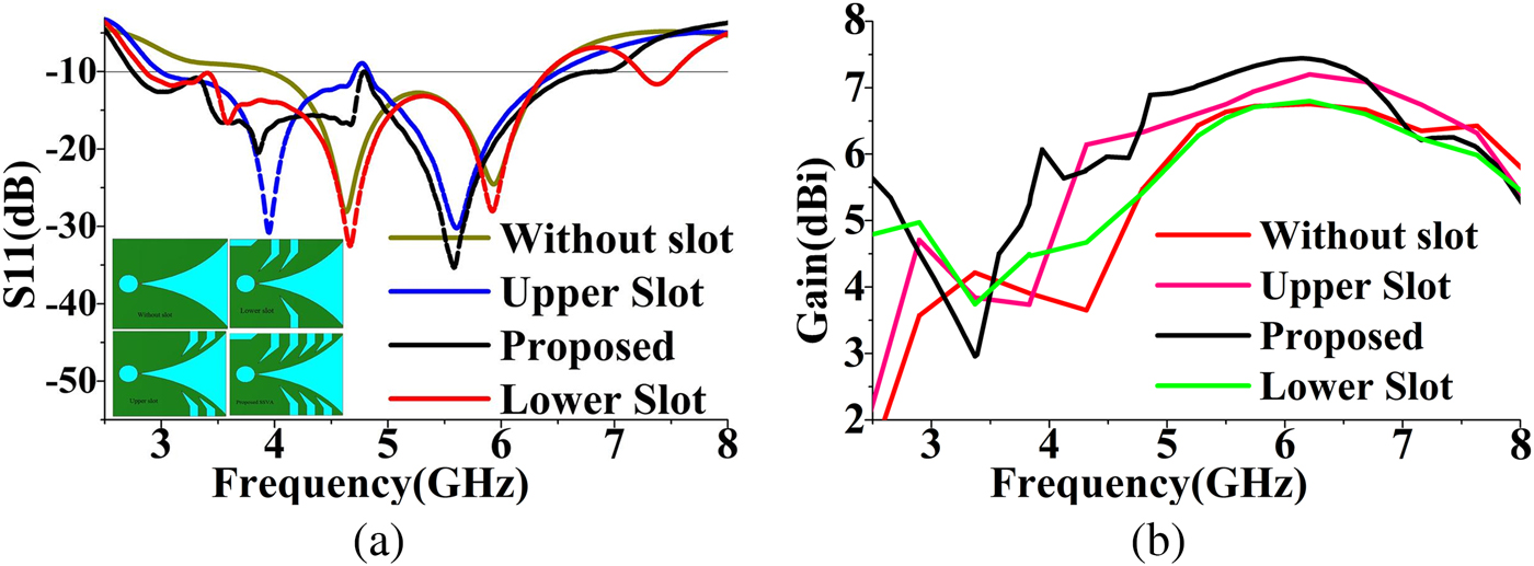
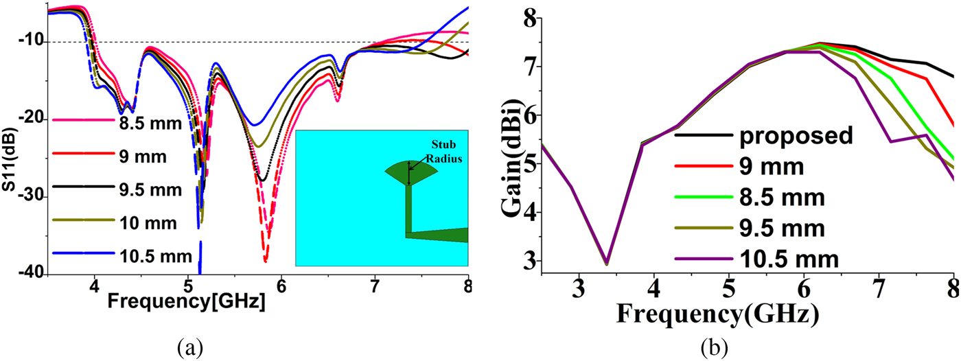
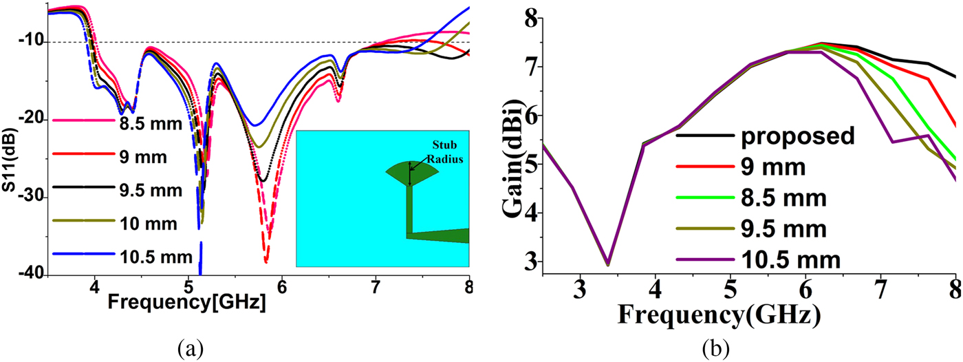
By using the modified radiating fins (proposed) configuration, better bandwidth (about 1.8 GHz increased) and gain (about 0.8 dBi more) have been achieved. The effect of stub radius to reflection coefficient and gain is shown in Fig. 3. By observing from 8.5 to 10.5 mm, it gives about 500 MHz improved bandwidth and 0.3 dBi higher gain for 10 mm stub radius. It is so, because the stub radius is proportional to the flare height. A strong surface current is raised around the cavity, which influences the directivity of the antenna.
Effect of stub radius to the (a) S 11 and (b) gain.
III. ANTENNA PERFORMANCE ANALYSIS
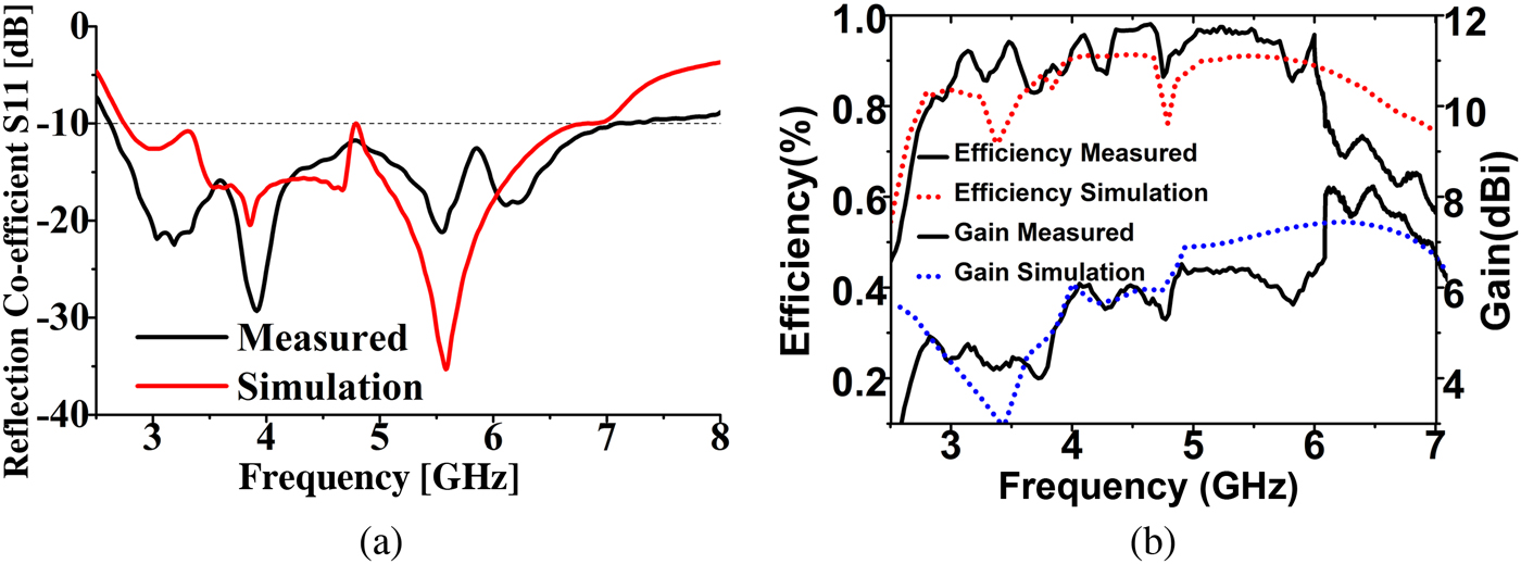
To verify how the side slot structure improves reflection coefficient, gain, and the efficiency with the reduced size, the SSVA is presented in Fig. 1(b). The proposed antenna has been analyzed and optimized using the software CST microwave studio built-in trust region framework under local optimization. The measured results were obtained using the Agilent E8362C vector network analyzer and Satimo near-field measurement laboratory (UKM StarLab) using Satimo passive measurement and SatEnv software. The −10 dB operating bandwidth of proposed SSVA is 2.7–7 GHz with two resonants at 3.83 and 5.56 GHz, which cover typical MBI shown in Fig 4(a). The measured and simulated results have good agreement though a little discrepancy is observed. The discrepancies between simulated and measured results can be attributed to fabrication tolerance and the coaxial cable losses during measurement, which was not considered in simulation.
Simulated and measured (a) S 11, (b) efficiency and gain.
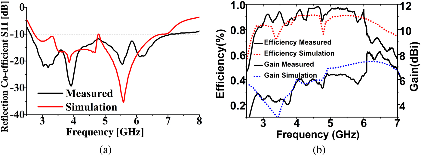
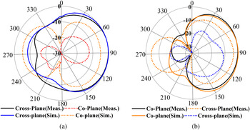
The peak gain of proposed prototype is 7.7 dBi and the radiation efficiency is about 86% on an average over the operating bandwidth shown in Fig. 4(b). Antenna parameter S 11 is affected by stub angle, substrate type, and Cd, whereas gain is affected by stub radius. The modified radiating fins play a vital role on both S 11 and gain. The measured and simulated radiation patterns in two principal planes – namely co-plane and cross-plane at resonant frequencies – are displayed in Fig. 5. According to the satimo measurement laboratory, the xz-plane is taken as co-plane where φ = 0° and z-plane is taken as a cross-plane where φ = 90°. The main beam is in the boresight. More than 10 dB front-to-back ratio and absence of side lobe ensure the higher range of the scattered signal with low unwanted noise and higher directivity, which is required for microwave imaging applications. The slots in the radiating fins remarkably change the antenna characteristics, especially increases the operating bandwidth, gain, and efficiency.
Measured and simulated radiation patterns: (a) 3.83 GHz, (b) 5.5 GHz.

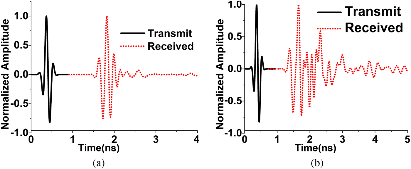
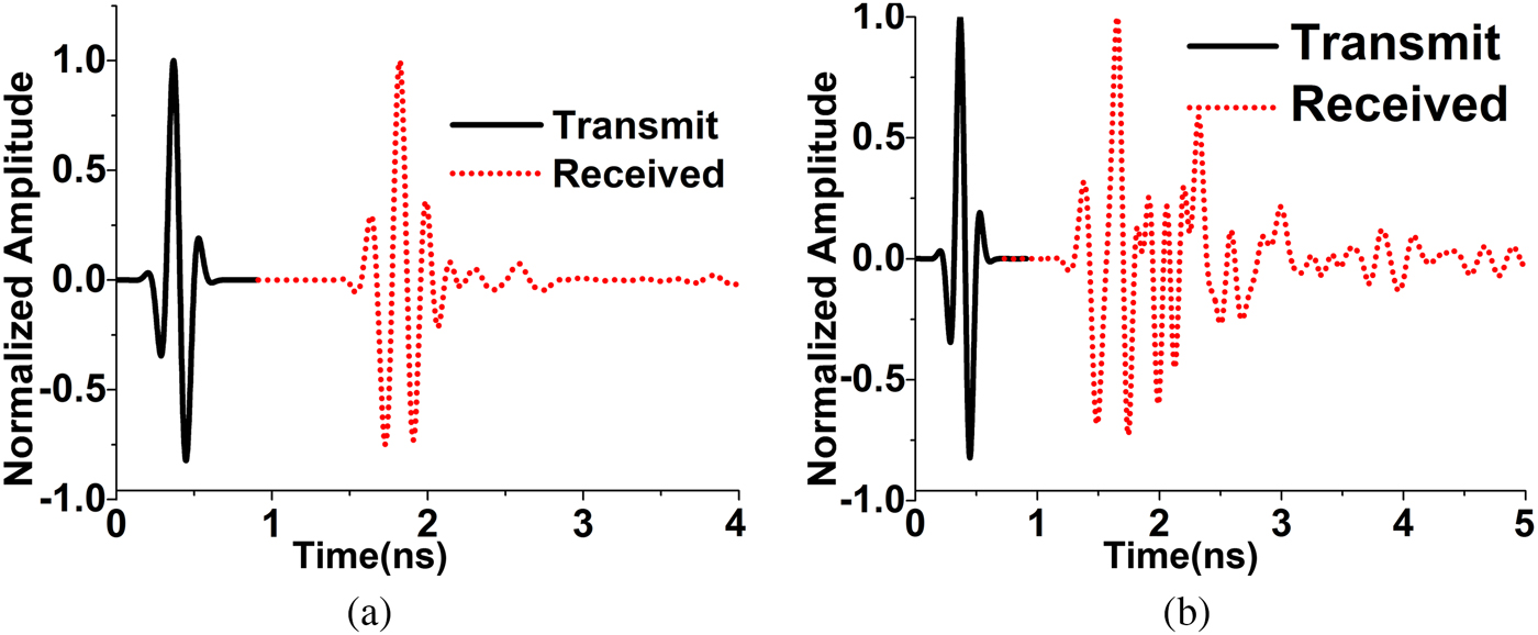
The normalized antenna performance in the face-to-face and side-by-side orientation with the distance of 230 mm is shown in Fig. 6. From the transmitting and receiving pulse, it is observed that in the face-to-face orientation the signal has a lower attenuation than that of the side-by-side orientation. For this, the antenna is recommended to use face-to-face orientation in microwave imaging applications. The highest value of cross-correlation among transmitting and receiving pulse evaluates the signal distortion presented as fidelity factor. The fidelity factor for face to face is 0.93 and for side by side is 0.61, which prove the directionality and lower distortion of the signal.
Transmitted and received pulse in (a) face to face and (b) side by side.
By considering the physical size of antenna, the minimum quality factor club can be obtained from [Reference Mavridis, Anagnostou and Chryssomallis8] Qlb = ηQ, where Q = 1/k
3
a
3 + 1/ka, wave number k = 2π/λ, and a is the sphere radius, the smallest sphere that encloses the antenna. The upper band of bandwidth efficiency product
 $(B\eta r)_{ub} = 1/\sqrt 2 [1/ka + 1/k^3a^3]^{ - 1}$
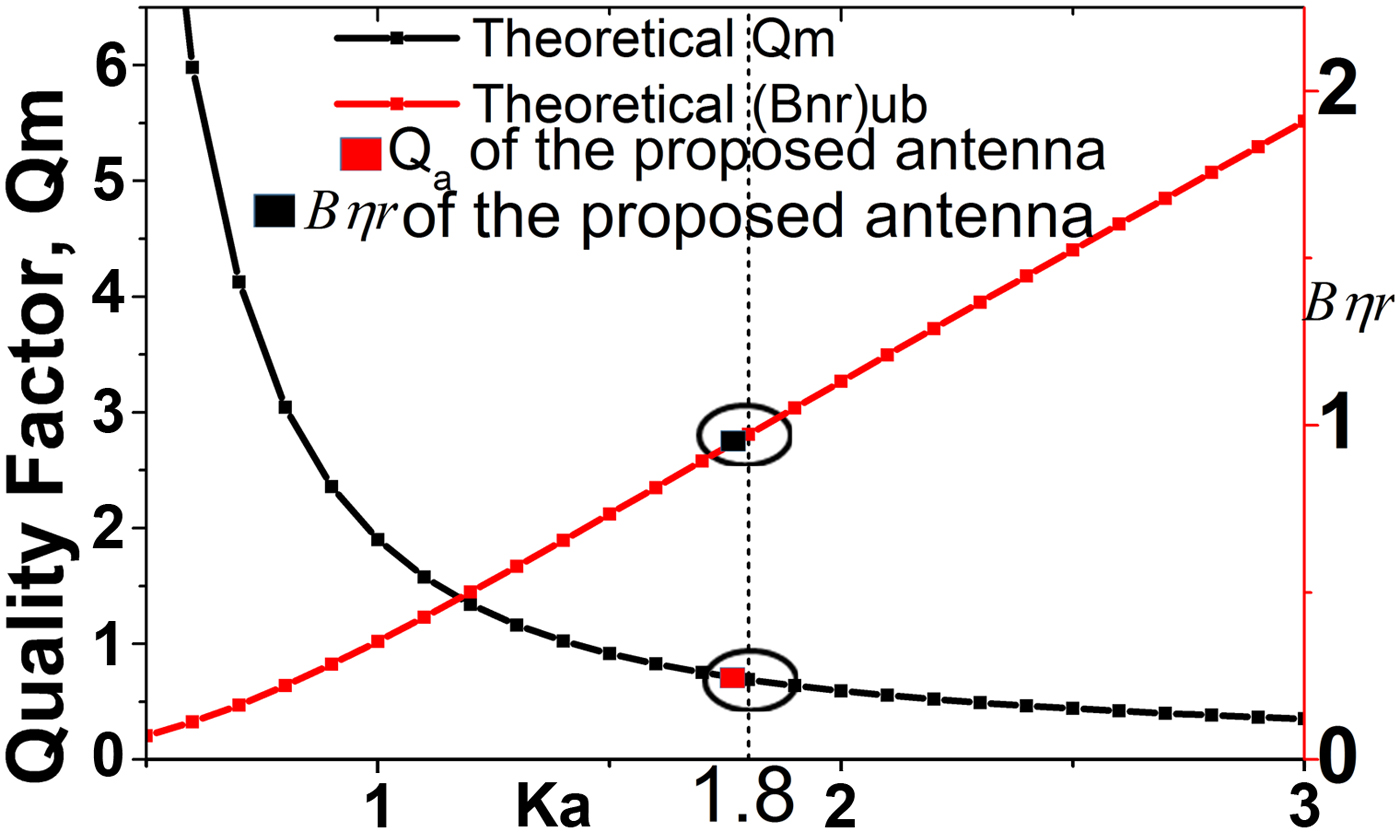
Fig. 7 shows the Qm and (B
ηr)ub for the antenna with the peak efficiency 89% and for different values of ka.
Theoretical limits and calculated Qa and (B ηr) ub .
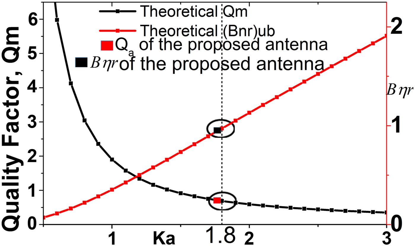
With the value of using the resonant bandwidth of proposed antenna ka = 1.8. From the curve, it can be noted that for ka = 1.8, the minimum limit of Qm is 0.69 and limit of (B ηr)ub is 0.97. The quality factor of the presented antenna is estimated as:
 $$Q_a = \displaystyle{{2\sqrt \beta} \over B}\quad {\rm Where}\quad \sqrt \beta = \displaystyle{{s - 1} \over {2\surd s}} \le 1.$$
For the maximum allowable VSWR s = 2, the proposed antenna achieved Qa = 0.73 and B ηr = 0.95. From the graph, the resultant value and the attainable values are close to the antenna parameters which prove the antenna design optimum.
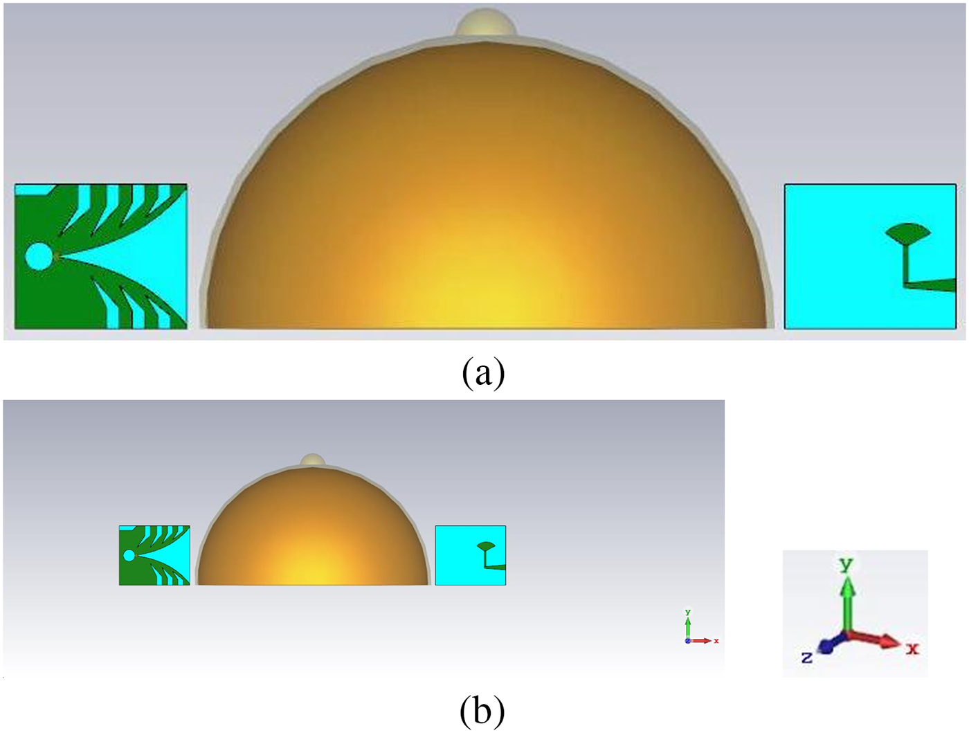
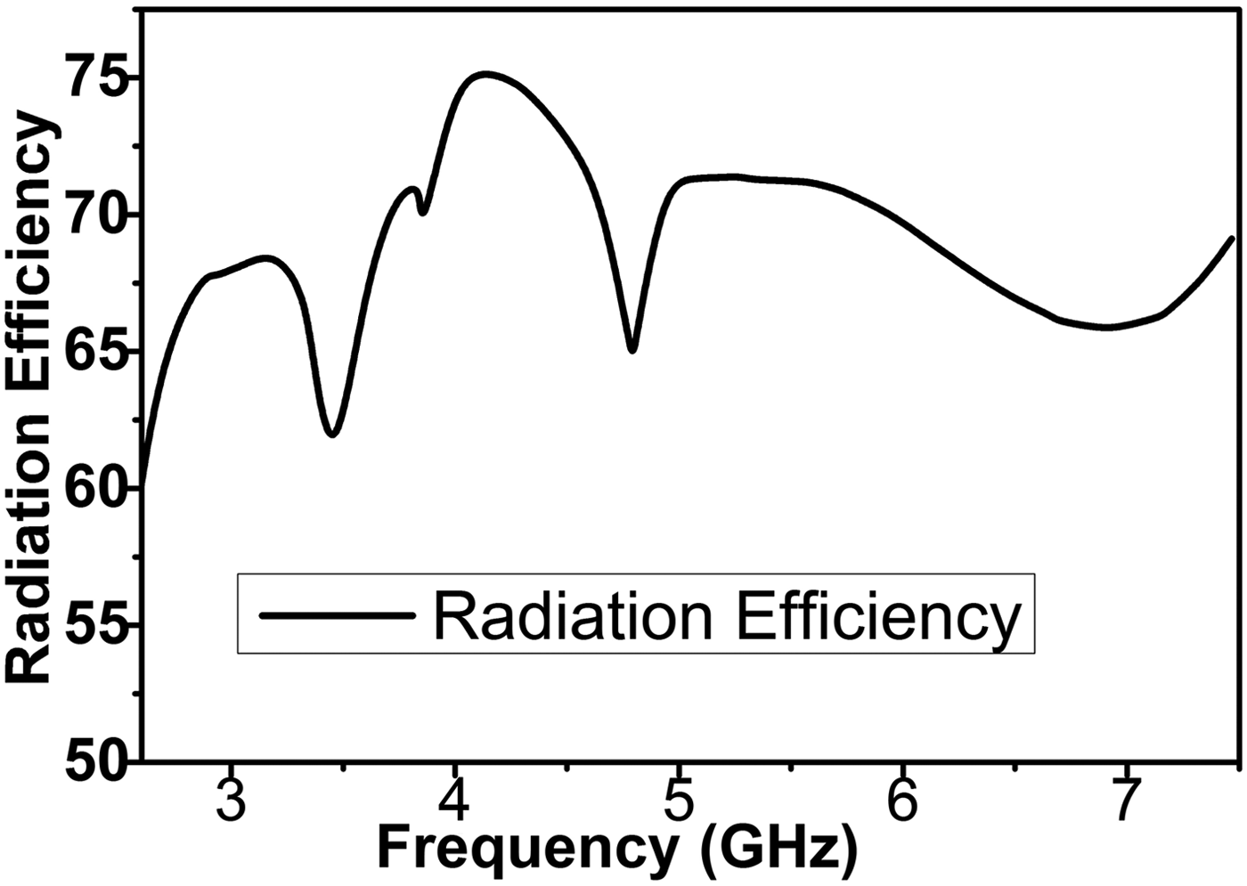
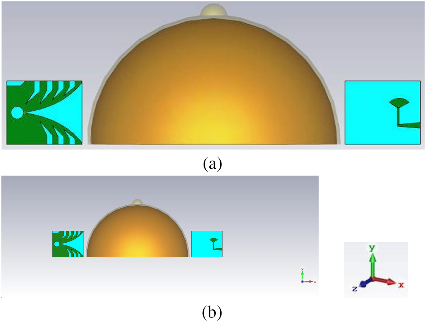
Figure 8 shows the simulation model of breast with proposed Vivaldi antenna. The antenna is kept at the breast phantom and effects of breast tissues are studied. To study the power coupled to the breast tissue, we compute the power radiated from the surfaces of a breast model with radius of 90 mm and height is 100 mm shown in Fig. 8. The antennas are placed at 5 mm distance from breast phantom. The phantom contains four layers, namely, the skin layer, the breast tissue layer or fat, and the normal air layer. The skin layer has the following properties: dielectric constant = 38, thickness = 2.5 mm, and conductivity = 1.49 S/m. The breast tissue layer has a maximum width of 8.75 cm, with conductivity = 0.141 S/m and dielectric constant = 5.14. The radiation efficiency of proposed SSVA prototype with breast model is shown in Fig. 9. The radiation efficiency is around 70% over the bandwidth with breast model whereas without model is more than 80%.
Cross-section of breast model simulation setup: (a) front view, (b) perspective view.
Radiation efficiency of proposed prototype with breast model.

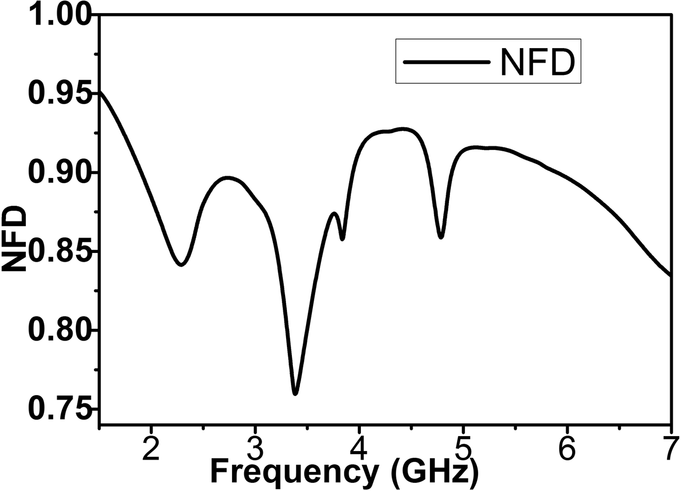
The near field directivity (NFD) factor is computed using the formula in [Reference Amineh, Trehan and Nikolova9, Reference Amineh, Ravan, Trehan and Nikolova10], which is the ratio of radiated power through the front of the antenna and the total power radiated through the surface of the breast model. Figure 10 shows the NFD factor for proposed SSVA. About 90% of the total power is radiated into the breast tissue.
Simulated NFD for the proposed SSVA.

IV. CONCLUSION
A novel compact SSVA for microwave imaging applications, especially for MBI, has been measured and characterized. In SSVA, all antenna parameters are adjusted and radiating fins are modified by etching several slots to reduce the size of the antenna with better antenna performance in terms of bandwidth, gain, efficiency, directivity for special application in the medical imaging system. The proposed antenna achieves −10 dB operating bandwidth of 4.3 GHz (2.7–7 GHz). The radiation pattern shows directive radiation pattern with 7.7 dBi peak gain, average efficiency 86%, which is better than recently published antennas. The higher value of fidelity factor finds the satisfactory pulse handling capacity of proposed SSVA. Close matching of the theoretical and estimated value of quality factor ensures the optimum antenna design. The compact structure and the covering frequency of typical breast imaging bandwidth with higher gain and directivity ensure the proposed SSVA for using in MBI applications.
ACKNOWLEDGEMENT
This work is supported by the Ministry of Education Malaysia (MOE) under grant no FRGS/1/2014/TK03/UKM/01/1.
 Md. Zulfiker Mahmud is an Assistant Professor of AIS Department in Jagannath University Bangladesh. He received the B.Sc. and M.Sc. degrees in Computer Science and Engineering from Islamic University Kushtia, Bangladesh. Currently, he is working as a Ph.D. student in the Universiti Kebangsaan Malaysia (UKM), Malaysia. He has authored or co-authored a number referred journals and conference papers. He is currently a Graduate Research Assistant at the Department of Electrical, Electronic and Systems Engineering, UKM, Malaysia. His research interests include the microwave imaging, antenna design, satellite antennas, satellite communication, and wireless communication.
 Mohammad Tariqul Islam is a Professor at the Department of Electrical, Electronic and Systems Engineering of the Universiti Kebangsaan Malaysia (UKM). He is currently the Group Leader of the Radio Astronomy Informatics Group at UKM. He is the author of over 300 research journal articles, nearly 165 conference articles, and a few book chapters on various topics related to antennas, microwaves, and electromagnetic radiation analysis with 11 inventory patents filed. Thus far, his publications have been cited 1990 times and his H-index is 25 (Source: Scopus). He is now handling many research projects from the Malaysian Ministry of Science, Technology and Innovation and Ministry of Education, and some international research grants from Japan. His research interests include communication antenna design, radio astronomy antennas, satellite antennas, and electromagnetic radiation analysis.
 Md. Naimur Rahman is an Assistant Professor of Electrical and Electronics Engineering (EEE) Department in Patuakhali Science and Technology University (PSTU), Bangladesh. He received the B.Sc. (Engg.) degree in Computer Science and Engineering from Patuakhali Science and Technology University (PSTU), Bangladesh. Currently, he is working as a Masters student in the Universiti Kebangsaan Malaysia (UKM), Malaysia. He has authored or co-authored a number referred journals and conference papers. He is currently a Graduate Research Assistant at the Department of Electrical, Electronic and Systems Engineering, UKM, Malaysia. His research interests include the antenna design, satellite communication, and wireless communication.
 Touhidul Alam was born in Feni, Bangladesh in 1989. He received B.Sc. in Electrical and Electronic Engineering (EEE) from International Islamic University Chittagong (IIUC) in 2012 and Master of Space Science from the Universiti Kebangsaan Malaysia, 2015. Currently, he is pursuing his Ph.D. degree in the Universiti Kebangsaan Malaysia (UKM). From May 2012 to till now, he is working as an Assistant Professor at the International Islamic University Chittagong (IIUC). His publication includes over 16 research journal papers, nearly 12 conference papers, and two book chapters on various topics related to antennas, microwaves, and electromagnetic radiation analysis. His research interests include the antenna, RF, electromagnetic field and propagation, electromagnetic radiation, metamaterial applications and electromagnetic compatibility, and microwave imaging.
 Md. Samsuzzaman was born in Jhenaidah, Bangladesh in 1982. He received his B.Sc. and M.Sc. degrees in Computer Science and Engineering from the Islamic University Kushtia, Bangladesh in 2005 and 2007, respectively, and the Ph.D. degree from the Universiti Kebangsaan Malaysia, Malaysia 2015. From February 2008 to February 2011, he worked as a Lecturer at the Patuakhali Science and Technology University (PSTU), Bangladesh. From February 2011 to 2015, he worked as an Assistant Professor at the same university. He is now working as an associate professor at the same university. He has authored or co-authored approximately 50 referred journals and conference papers. His research interests include the communication antenna design, satellite antennas, and satellite communication.