I. INTRODUCTION
Fe-6.5 wt%Si alloy, as an excellent soft magnetic material, exhibits high permeability, low coercive force, and near-zero magnetostriction.Reference Yuan, Li, Shen and Zhang1, Reference Phway and Moses2 It has wide application prospects in high frequency fields because of its advantages in reducing the consumption of energy and noise pollution, such as transformers, power generators, and electric relay.Reference Zbroszczyk, Ciurzynska, Olszewski, Hasiak, Tanaka and Enokizono3 However, it is impossible to fabricate Fe-6.5 wt%Si alloy thin sheet by the conventional rolling process due to its brittleness at room temperature,Reference Komatsubara, Sadahiro, Kondo, Takamiya and Honda4 which impeded its industrial application seriously.
Previous studies have reported that the workability of some brittle alloys, such as Ni3Al,Reference Hirano5 Ni50Al20Fe30,Reference Chen, Zheng, Li, Yu, Tang and Hu6 and Al–Si alloy,Reference Drar and Svensson7 can be improved by directional solidification. This improvement is mainly attributed to the columnar grains with less casting defects, less transverse grain boundaries, and more low-angle grain boundaries, which effectively suppresses the propagation of cracks during deformation. Furthermore, it was reported that B element can effectively reduce brittleness of some intermetallics at room temperature because of its contribution to increases both in bonding energy of grain boundary and density of domain boundary, reduction in the antiphase domain boundary energy, and the long-range order parameters as well as grain refinement.Reference Masahashi8–Reference Kim, Pan, Lin, Wang, Lin and Chen10 Grain size and ordering–disordering phenomena of high-silicon Fe–Si alloys produced by conventional casting or spray forming could be controlled by heat treatment.Reference Viala, Degauque, Fagot, Baricco, Ferrara and Fiorillo11–Reference Haiji, Okada, Hiratani, Abe and Ninomiya13
Therefore, the workability of an Fe-6.5 wt%Si alloy can be improved significantly by the combination of directional solidification, heat treatment, and boron microalloying methods. In this work, an Fe-6.5 wt%Si-0.05 wt%B alloy (or also referred to as Fe-6.5 wt%Si alloy) with columnar grains was fabricated by a directional solidification process. Effects of precipitated phase and order degree of the Fe-6.5 wt%Si alloy with columnar grains on bending mechanical properties and fracture surface were investigated. Finally, the mechanism of the effects was discussed.
II. EXPERIMENTAL PROCEDURES
An Fe-6.5 wt%Si alloy foundry alloy was prepared by vacuum melting furnace and cut into Ø8 × 100 mmReference Phway and Moses2 rod by electric discharge machining. The rod was directionally solidified to obtain columnar grains using zone melting equipment. Solidification was carried out in an Ar atmosphere followed by cooling with water. The temperatures of the molten alloy and cooling water were about 1500 and 25 °C, respectively. The solidification rate was 1 mm/min. The rectangle samples 2 × 5× 35 mmReference Zbroszczyk, Ciurzynska, Olszewski, Hasiak, Tanaka and Enokizono3 in size were cut from the ingot with columnar grains before heat treatment.
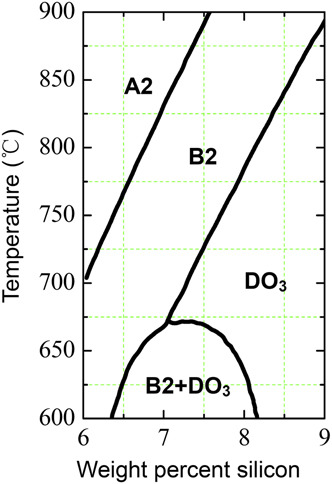
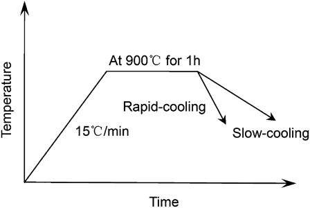
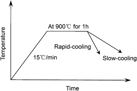
According to Fe–Si binary phase diagramReference Swann, Granas and Lehtinen14, Reference Shin, Bae, Kim, Lee, Lee, Lavernia and Lee15 (Fig. 1), the ordering reaction from A2 (disorder body-centered cubic) to B2 in Fe-6.5 wt%Si alloy is suppressed at temperature above 770 °C. The two-phase field of B2 + DO3 occurs in this alloy at temperature below 620 °C. In consideration of effects of trace elements and impurity element on crystal structure of Fe–Si alloy, burning loss of the alloy at high temperature, and high temperature intergranular oxidation, the samples were conducted by the heat treatment processes, as shown in Fig. 2, based on our previous work. Oil quenching (rapid cooling) and furnace cooling (slow cooling) were adapted to investigate the effect of microstructural change on mechanical property of the Fe-6.5 wt%Si alloy treated by different cooling rates.
Fe–Si alloy binary phase diagram.Reference Swann, Granas and Lehtinen14, Reference Shin, Bae, Kim, Lee, Lee, Lavernia and Lee15

Graph of heat treatment processes.
Variation of precipitated phase at the same position in the Fe-6.5 wt%Si alloy samples before and after heat treatment was observed by light optical microscopy. To ensure the accuracy of the experiments, the same position was marked by Vickers hardness tester before and after heat treatment. Heat treatment was carried out in an Ar atmosphere, and the alloy surface of about 10-μm thick was grinded to reduce the influence of burning loss of alloy elements on the accuracy of the experiment. All the samples were polished and etched with a solution of 3.5% HNO3 and 96.5% CH3COOH for 1 min at room temperature and bending mechanical properties of Fe-6.5 wt%Si alloy samples were measured according to China National Standard GB/T 14452-93. The composition of precipitated phases and matrix were measured by an electro-probe microanalyzer (JXA-8100; JEOL Ltd., Tokyo, Japan). A CAMBRIDGE S-360 (Cambridge Scientific Instrument Ltd., Cambridge, England) scanning electron microscopy was used to observe fracture surfaces of the samples. A JEM-200CX transmission electron microscopy (TEM; JEOL Ltd., Tokyo, Japan) operated at 200 kV was used to investigate the variation of order degree before and after heat treatment.
III. RESULTS
A. Changes in morphology and amount of precipitated phases
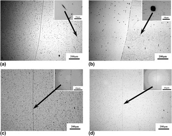
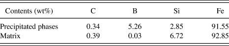
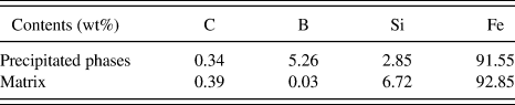
After heat treatment at 900 °C for 1h followed by slow or rapid cooling, the apparent changes in morphology of precipitated phase can be observed in the Fe-6.5 wt%Si alloy, as shown in Fig. 3. The needle-like precipitated phases of directional solidified samples before heat treatment are dispersively distributed in the matrix with the size of 3–10 μm, as shown in Figs. 3(a) and 3(c). After heat treatment, the morphology of precipitated phases is shown in Figs. 3(b) and 3(d), where the same region observed is selected before and after heat treatment. One can see that original needle-like phases are spheroidized obviously and the amount of precipitated phases was decreased. The particles with average size of 10 μm are found in the slow cooling sample, whereas particles with average size of 3 μm are found in the rapid cooling sample. An electro-probe microanalyzer was used to detect the composition of the precipitated phases and matrix nearby them, as listed in Table I. The compositions of the precipitated phases were almost similar with enrichment of boron and dilution of silicon (boron-rich precipitated phases).Reference Fu, Zhang, Yang and Xie16
Morphology and amount of precipitated phases before and after heat treatment (a) directional solidified sample before slow cooling process; (b) sample after slow cooling process; (c) directional solidified sample before rapid cooling process; (d) sample after rapid cooling process.

Compositions of the precipitated phases and matrix nearby them.
The above microstructural change is closely related to redissolution and redistribution of boron in the Fe-6.5 wt%Si alloys. During the heat treatment, the precipitated phases dissolve substantially due to the diffusion of fine boron atoms into the matrix. During the subsequent cooling process, cooling speed has a great effect on the redistribution of element atoms. For the slow cooling process, it took enough time for the redistribution of boron atom, which induces the spheroidization and growth of the precipitated phase. For the rapid cooling process, both the amount and size of the precipitated phases decrease evidently due to insufficient diffusion of boron atoms, which makes it difficult be a required concentration for forming new phases.
B. Changes in order degree of Fe-6.5 wt%Si alloys
It is generally believed that long-range order phases will form in solid solution once the Si content is above 5.8 wt% in Fe–Si alloys.Reference Haggstrom, Granas, Wappling and Devanarayanan17 The ordered structure of Fe–Si alloys can be affected significantly by the cooling process.
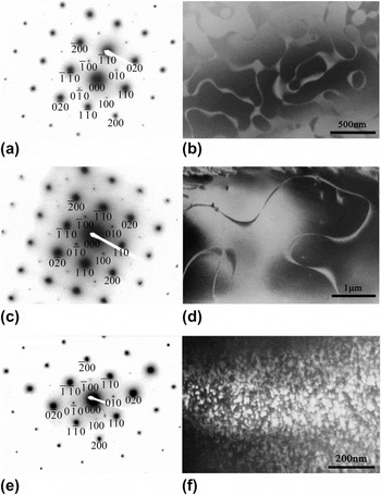
For analyzing the size of ordered phase domain and density of phase domain boundary, TEM images of the phases in the Fe-6.5 wt%Si alloys before and after heat treatment are shown in Fig. 4, where Figs. 4(a), 4(c), and 4(e) are electron diffraction patterns and Figs. 4(b), 4(d), and 4(f) are dark field images of [010] reflection in <001> zone axis.
Electron diffraction spots in <001> zone axis and dark field images of [010] diffraction spots (the diffraction spots represent {100} planes are superlattice spots). (a) Electron diffraction spots of directional solidified samples; (b) dark field images of directional solidified samples; (c) electron diffraction spots of slow cooling samples; (d) dark field images of slow cooling samples; (e) electron diffraction spots of rapid cooling samples; (f) dark field images of rapid cooling samples.

From Figs. 4(a), 4(c), and 4(e), the difference in the {100} diffraction intensity of superlattice is slight in the different samples and it is difficult to reveal the changes in the order degree of the samples. To further reveal the difference of the order degree of the samples before and after heat treatment, the size of the ordered phase domain can be measured to detect the change of the order degree of the alloy according to the previous study.Reference Shin, Bae, Kim, Lee, Lee, Lavernia and Lee15, Reference Ourmazd and Bean18–Reference Yasuda and Umakoshi20 From Figs. 4(b), 4(d), and 4(f), one can see that the size of the ordered phase domain in the directional solidified sample is ∼0.2–0.5 μm, and the antiphase domain boundary has a large width and high density. The size of the ordered phase domain in the slow cooling sample is ∼3–5 μm with low density of antiphase domain boundary, as shown in Fig. 4(d). On the other hand, the size of the ordered phase domain in the rapid cooling sample is only ∼20–50 nm, and the density of the antiphase domain boundary increased obviously compared with those of the directional solidified and the slow cooling samples, as shown in Fig. 4(f). Since the ordered arrangement of the solute atoms is affected by antiphase domain boundary, the existence of antiphase domain boundary result in some kind of disordering. This means that the ordered degree of the alloy can be decreased with an increase in amount of antiphase domain boundary. Compared with the directional solidified sample, order degree of the slow cooling sample increased, whereas order degree of the rapid cooling sample decreased. It is supposed that rapid cooling process can decrease the order degree of the Fe-6.5 wt%Si alloy effectively.
C. Three-point bending property and fracture morphology of Fe-6.5 wt%Si alloys
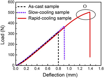
The three-point bending load–deflection curve of the Fe-6.5 wt%Si alloy by various treatments is shown in Fig. 5. It can be found that both the maximum fracture load and maximum fracture deflection are increased slightly in the slow cooling sample compared with the directional solidified samples. On the other hand, the two parameters are increased remarkably in the rapid cooling sample. In addition, large plastic deformation was observed in the latter before the fracture occurred and the increase of the load with the deflection reduced, as indicated by ‘O’ in Fig. 5.
Three-point bending load–deflection curve of Fe-6.5 wt%Si alloys undergoing varied treatments.

Compared with the directional solidified sample, the fracture deflection of the slow cooling sample was increased from 0.80 to 0.91 mm (increase by 13.8%). Furthermore, the rapid cooling sample had the maximum bending mechanical properties with the fracture deflection increased by 73.8% (from 0.80 to 1.39 mm). This implies that rapid cooling process can substantially increase the bending fracture resistance of the Fe-6.5 wt%Si alloy.
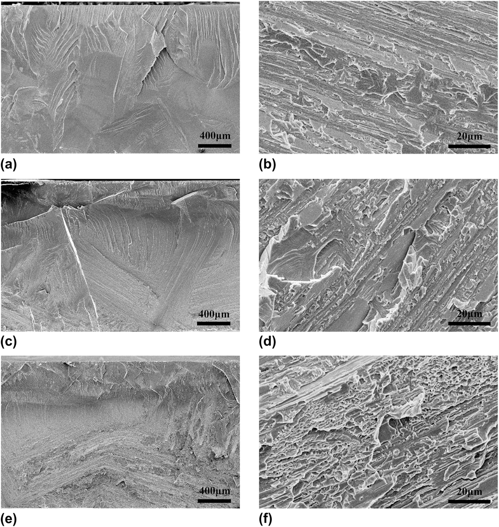
Figure 6 shows the fracture morphology of the Fe-6.5 wt%Si alloy before and after heat treatment, where the upper half of Figs. 6(a), 6(c), and 6(e) is compressive stress region and the lower half is tensile stress region. Figures 6(b), 6(d), and 6(f) are magnified images of tensile stress regions.
Bending fracture morphology of the Fe-6.5 wt%Si alloy before and after heat treatment. (a) bending fracture morphology of the directional solidified sample; (b) magnified image of (a); (c) bending fracture morphology of the slow cooling sample; (d) magnified image of (c); (e) bending fracture morphology of the rapid cooling sample; (f) magnified image of (e).
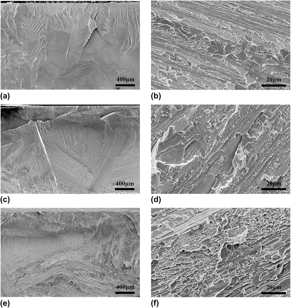
The three different samples have the similar fracture mode basically in compressive stress region, termed as typically brittle cleavage fracture. This implies that rapid propagation of crack occurred without apparent plastic deformation during the final period of fracture. However, obvious differences of fracture morphology in tensile stress regions can be observed in different samples. The fracture surface of the directional solidified sample is characteristic mainly of smooth fracture plane and river-like cleavage pattern in the same direction, as shown in Fig. 6(b). The rough fracture surface appears in the slow-cooling sample and some fine pits are predominated in the rapid cooling sample, as shown in Figs. 6(d) and 6(f), which indicates that adequate energy should be required for crack initiation and propagation.
IV. DISCUSSION
A. Amount and effect of adding boron element
According to previous studies,Reference Liu, White and Horton21–Reference Liu, George and Oliver24 it was demonstrated that the segregation of boron mainly occurred at grain boundary and antiphase domain boundary. Such behavior was favorable for refining grain refinement, strengthening grain boundary, increasing density of phase domain boundary, and reducing order degree in intermetallics. Apparently, the brittleness of intermetallics was decreased by adding trace element boron, such as Ni3Al,Reference Liu, White and Horton21 FeAl,Reference Crimp and Vedula22 Ni3Ge,Reference Xu and Schulson23 and Ni3SiReference Liu, George and Oliver24 alloys.
Kim et al.Reference Kim, Pan, Lin, Wang, Lin and Chen10 reported that grains of an Fe-6.5 wt%Si alloys fabricated by conventional casting process can be refined through adding certain a mount of element boron, and the plasticity of the Fe-6.5 wt%Si alloy can be improved by adding 530-ppm boron element. Zhang et al.Reference Zhang, Chen, Bei, Li, Ye, Chen and Liu25 have investigated the microstructure of an Fe-6.5 wt%Si alloy with the amount of boron element 430 ppm, which was fabricated by directional recrystallization. Therefore, 500-ppm boron element was added into the Fe-6.5 wt%Si alloys for improving its plasticity in this study. However, our results indicated 500-ppm boron was too much for this alloy fabricated by directional solidification process, and further clarification for an appropriate amount of boron should be done in the future.
B. Effects of morphology and amount of the precipitated phase on bending properties of Fe-6.5 wt%Si alloy
In the directional solidified sample, some boron-rich brittle phases like needle were formed in the alloy. During deformation, the incompatible strain can be favorably induced due to the difference in mechanical properties between the precipitates and matrix, and the dislocation slip was hindered at the precipitates. Such behaviors induced stress concentration at the precipitates and cracks. On the other hand, when the crack propagates to the region adjacent to brittle phases, two types of propagation mechanisms may workReference Wang, Liu, Weng, Song, Huo and Xie26: when the angle between axial orientation of precipitated phases and propagation direction of the cracks is high, precipitated phases will be broken and the crack propagation will proceed; when the angle is low, the crack can also propagate due to detachment of precipitated phases from the matrix. Whatever direction precipitated phases are oriented, the needle-like phases accelerate initiation and propagation of crack and decrease the bending stress, deflection, and absorption capability of fracture energy of the directional solidified sample.
After the slow cooling process, the boron-rich phases of the Fe-6.5 wt%Si alloy were spheroidized. Such morphology favorably reduced the stress concentration at tip of the precipitated phase, which improved the bending deflection and energy required for crack initiation and propagation. After the rapid cooling process, both the size and amount of precipitated phases decreased remarkably, which further reduced probability of crack initiation and propagation speed. As a result, the bearing bending stress, bending deflection, and absorption capability of fracture energy of the Fe-6.5 wt%Si alloy can be enhanced significantly by the rapid cooling process.
C. Effect of order degree on bending properties of Fe-6.5 wt%Si alloy
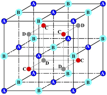
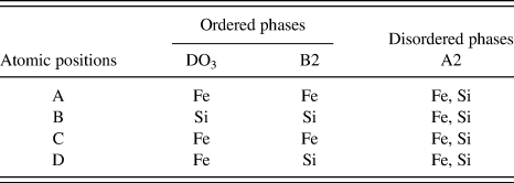
From Fig. 1, it can be found out that the structure of Fe-6.5 wt%Si treated by heating and cooling mainly consists of disordered A2 phase and ordered B2, DO3 phases. Figure 7 shows a big unit cell of the Fe-6.5 wt%Si alloy which contains eight body-centered small unit cells. The atomic positions of A2, B2 and DO3 are listed in Table II.
A big unit cell of the Fe-6.5 wt%Si alloy.Reference Swann, Granas and Lehtinen14, Reference Shin, Bae, Kim, Lee, Lee, Lavernia and Lee15

Atomic positions of some disordered and ordered phases in Fe-6.5 wt%Si alloy.Reference Swann, Granas and Lehtinen14, Reference Shin, Bae, Kim, Lee, Lee, Lavernia and Lee15
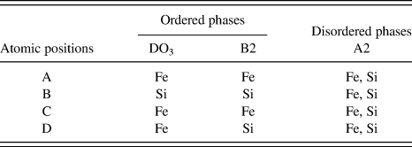
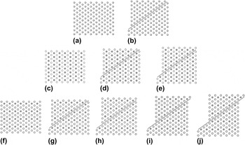
For analyzing the difficulty level of sliding deformation in the three different structures, the distribution of Fe and Si atoms at {110} planes can be graphically depicted in Figs. 8(a), 8(c), and 8(f), based on Fig. 7 and Table II.
Distribution of Fe and Si atoms at {110} planes of Fe–Si alloys. (a) A perfect A2 crystal structure; (b) distribution of Fe and Si atoms after a <111>/4 dislocation slip in A2 crystal structure; (c) a perfect B2 crystal structure; (d) and (e) distribution of Fe and Si atoms after one and two <111>/4 dislocation slip in B2 crystal structure; (f) a perfect DO3 crystal structure; (g)–(j) distribution of Fe and Si atoms after one-four <111>/4 dislocation slip in DO3 crystal structure. Where  indicates Fe or Si atom random occupation,
 indicates Fe atom occupation, and
 indicates Si atom occupation.

For a perfect crystal structure of A2 [Fig. 8(a)], after a <111>/4 dislocation slip occurs in the {110} plane, an entire dislocation slip cannot change the neighboring relationship between Fe and Si atoms. This means that the antiphase domain cannot form and the deformation mechanism of the alloy is simply entire dislocation slip.
For a perfect crystal structure of B2 [Fig. 8(c)], a <111>/4 dislocation slip at the {110} planes can change of the neighboring relationship between Fe and Si atoms [Fig. 8(d)] and produce an antiphase domain boundary with an energy γ1. An entire dislocation slip can be completed after another <111>/4 dislocation slip at {110} plane. As a result, the neighboring relationship between Fe and Si atoms at {110} atoms can return to the original state [Fig. 8(e)], and the deformation mechanism is superdislocation slip, which is achieved by slip of two dislocations and an antiphase domain boundary with an energy γ1.
For a perfect crystal structure of DO3 [Fig. 8(f)], a <111>/4 dislocation slip at the {110} planes can totally change the neighboring relationship between Fe and Si atoms [Fig. 8(g)], and produce an antiphase domain boundary with an energy γ1. The second <111>/4 dislocation can cause another antiphase domain boundary with an energy γ2 [Fig. 8(h)], and the third <111>/4 dislocation can also cause antiphase domain boundary with an energy γ1 [Fig. 8(i)]. After the fourth <111>/4 dislocation slip at {110} plane, the neighboring relationship between Fe and Si atoms at {110} atoms can return to the original state [Fig. 8(j)]. The deformation mechanism is superdislocation slip, which is achieved by slip of four dislocations and three antiphase domain boundaries.
In the directional solidified sample with high order degree, the deformation mechanism was predominated by the superdislocation slip, i.e., the slip was combined by multiple dislocations and antiphase domain boundary. After the rapid cooling process, the order degree of the sample decreased apparently and the bending properties were improved due to an increase in entire dislocation slip and a decrease in superdislocation slip during deformation. In contrast, after the slow cooling process the order degree of the sample increased and the bending properties were decreased due to a reduction in mobility of dislocation.
On the basis of the above experimental results and analysis, it was concluded that the morphology and amount of the precipitated phase, the size of the ordered phase domain, and the density of antiphase domain boundary of the Fe-6.5 wt%Si alloy can be well controlled by heat treatment at 900 °C for 1 h followed by slow or rapid cooling process. After a rapid cooling process, the improvement of the bending properties of the sample was increased remarkably due to the combining effects of the morphology and amount of the precipitated phase and reduction in order degree.
V. CONCLUSIONS
After heat treatment at 900 °C for 1 h followed by the slow cooling or rapid cooling process, original needle-like precipitated phases of an Fe-6.5 wt%Si alloy were spheroidized substantially. Compared with the directional solidified sample, the size of precipitated phases in the slow cooling sample was increased slightly, whereas the size and amount of precipitated phases in the rapid cooling sample were decreased.
The slow cooling and rapid cooling processes changed the order degree of the Fe-6.5 wt%Si alloy by altering the size of the ordered phase domain and density of antiphase domain boundary. Compared with the directional solidified sample with the size of ordered phase domain 0.2–0.5 μm, the size of the ordered phase domain of the slow cooling sample is ∼3–5 μm with lower density of antiphase domain boundary and higher order degree, whereas the size of the ordered phase domain of the rapid cooling sample is ∼20–50 nm with higher density of antiphase domain boundary and lower order degree.
Compared with the directional solidified sample, the fracture deflections of the slow cooling and rapid cooling samples were increased by 13.8% and 73.8%, respectively. The fracture surface of the rapid cooling sample was mainly featured as tear pit-like fracture instead of the quasi-cleavage fracture of the directional solidified sample. The bending properties of the Fe-6.5 wt%Si alloy were improved mainly due to the changes in morphology and amount of the precipitated phase as well as the reduction of order degree.
ACKNOWLEDGMENT
This work was supported by the National Basic Research Program (973 Program) of China under Contract Nos. 2006CB605200 and 2011CB606300.