I. INTRODUCTION
Nickel-based single crystal superalloys with a compound of γ/γ′ structure are widely used for hot-section turbine components.Reference Pollock and Argon1 The degeneration of nickel-based single crystal superalloys is generally correlated with the cutting of the γ′ phase by stacking-faults-related {111}<112> slipReference Kear, Leverant and Oblak2–Reference Link and Feller-Kniepmeier5 or APB-related {111}<110> slip.Reference Link and Feller-Kniepmeier5,Reference Feller-Kniepmeier and Link6 In general, cutting by stacking faults happens under the creep conditions of low temperature and high stressReference Kear, Leverant and Oblak2–Reference Link and Feller-Kniepmeier5,Reference Shimabayashi and Kakehi7 or thermomechanical fatigue (TMF) conditions.Reference Liu, Wang, Ai, Wang, Sun, Jin and Guan8
A number of studies have been carried out to understand the generation of superlattice stacking faults within the γ′ particles. Formation of extended configurations of intrinsic–extrinsic fault pairs with a net 1/3<112> Burgers vector has been proposed for the primary creep of Mar-M200 single crystals at 760 °C.Reference Kear, Leverant and Oblak2,Reference Kear, Oblak and Giamei4,Reference Kear, Giamei, Silcock and Ham9 Matrix dislocations in the γ channels with a Burgers vector of 1/2<110> are shown to be involved in the shearing configurations of γ′ particles.Reference Kear, Leverant and Oblak2,Reference Kear, Oblak and Giamei4,Reference Link and Feller-Kniepmeier5,Reference Decamps and Condat10,Reference Feller-Kniepmeier and Kuttner11 That is to say, the operation of 1/3<112> slip in the γ′ phase is associated with the dissociation of a single 1/2<110> matrix dislocation when it meets the γ′ precipitates.Reference Decamps and Condat10,Reference Feller-Kniepmeier and Kuttner11 It is also widely documented that two 1/2<110> matrix dislocations in γ phase with different Burgers vectors may meet at the γ/γ′ interfaces where the product 1/6<112> partials were trapped.Reference Kear, Giamei, Leverant and Oblak12,Reference Chen and Knowles13
Beside the occurrence of a common slip, formation of stacking faults is frequently related to the TMF deformation or creep deformation in nickel-based superalloys. Compared with the deep understanding of the nucleation and propagation mechanisms of the stacking faults in nickel-based superalloys, there are few reports on the dynamic behavior of the stacking faults during various deformation processes. In the present work, a reversible movement behavior of stacking faults during TMF tests will be reported and explained for a nickel-based single crystal superalloy. It is essential to know the evolution of the stacking faults to understand the TMF properties thoroughly.
II. EXPERIMENTAL
The nickel-based single crystal TMS-82 superalloy was chosen for the present work. The nominal composition of this alloy in weight percent is as follows: Al 5.3, Ti 0.5, Co 7.8, Cr 4.9, Mo 1.9, W 8.7, Ta 6.0, Hf 0.1, Re 2.4, and the balance of Ni. The material was solution heat treated both at 1300 °C for 1 h and 1320 °C for 5 h followed by a two-stage aging process with 1150 °C for 4 h and 870 °C for 20 h. The volume fraction of the γ′ phase is about 60%, and the average size of the γ′ cuboids is 0.4 μm. The specimens were machined from cast bars with their longitudinal axis parallel to the [001] direction. Cylindrical specimens for TMF tests with a gauge length of 35 mm and a diameter of 5 mm were prepared by mechanical machining and grinding.
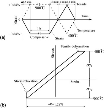
TMF tests were carried out on a MTS 810 servo-hydraulic TMF machine with a capacity of ±50 kN. To simulate the actual conditions of blades and vanes, the following experimental conditions were selected [Figs. 1(a) and 1(b)]: temperature range, 400–900 °C in air; total strain range, εt = 1.28% (±0.64%); frequency, (0.1 + t h) (h)/cycle, where t h = 1 h was the hold time at the maximum testing temperature (900 °C); wave form, trapezoidal; phase, out-of-phase.
The experimental conditions during TMF tests. (a) Illustration of TMF test; (b) schematic drawing of the hysteresis loop.

To study the dynamic evolution process of the microstructure, the TMF cycling was stopped at different stages during compression–tension tests. So several specimens were obtained at different stages including those (i) after the first stress relaxation; (ii) after the first tensile plastic deformation; and (iii) after the second stress relaxation. Special attention was paid to the behavior of the stacking faults during compression–tension cycling.
Foils for transmission electron microscope (TEM) observation were obtained by cutting 0.3-mm-thick discs perpendicular to the tensile axis of the TMF tested specimens using a low speed diamond saw. They were mechanically thinned to 40–50 μm and then electropolished using a solution of 10% perchloric acid in methanol at −20 °C. The microstructures of all the specimens were studied by the use of a JEOL 2000 FX II TEM (Tokyo, Japan).
All the TEM micrographs were imaged under two-beam conditions: dark field and bright field. The nature of the displacement vectors of stacking faults and Burgers vectors of partial dislocations is determined by using computer image simulation: an image computation program based upon TWODIS.Reference Head, Humble, Clarebrough, Morton and Forwood14
III. RESULTS
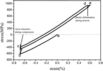
Figure 2 illustrates the stress–strain relationship for the <001>-oriented specimen during the initial TMF cycling. The TMF test started from the point “a” with a compression process. During the hold time of 1 h at the maximum compression strain, there is a stress relaxation process starting from the point “b” to “c.” Then from the point “c” to “d,” the TMF test proceeded gradually from compression to tension. Around the temperature of 400 °C, a tensile plastic deformation was present (from the point “d” to “e”) on the top of the curve. Thereafter, the test switched from the present tension to the following compression (the second compression) from the point “e” to “f.” It is emphasized that the curve corresponding to the second compression stage does not coincide with the first one (ab). The second stress relaxation stage from the point “f” to “c” is remarkably shorter than the first one “bc.”
The stress–strain curve for the <001>-oriented specimen during the initial TMF cycling.

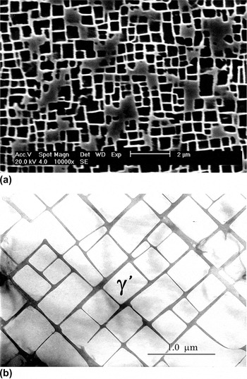
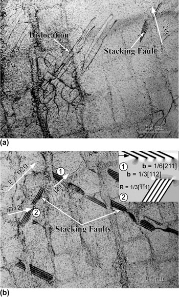
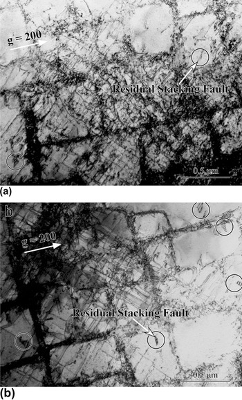
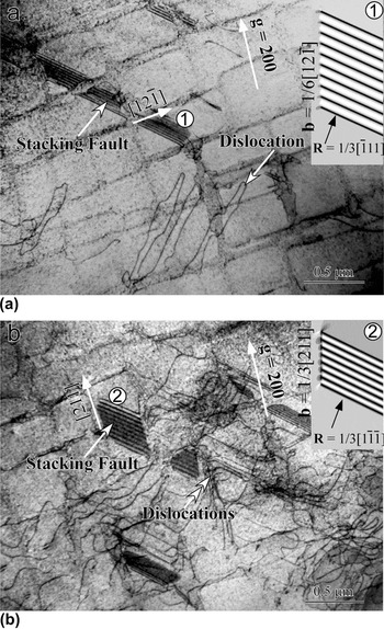
The microstructure of the TMS-82 superalloy is typically composed of the γ matrix and a large number of γ′ cuboid-shaped precipitates as shown in Fig. 3. Before testing, it was found that there was a lack of dislocations in the superalloy [Fig. 3(b)]. The microstructure after the first stress relaxation is shown in Fig. 4. Compared to the simple γ/γ′ structure in the alloy before test, two kinds of defects were introduced during compression deformation. There were some 1/2<110> dislocations in the horizontal γ channels, which were moving in the mode of cross slip [Fig. 4(a)]. Stacking faults (marked by arrows) appeared as a typical characteristic of shear in the γ′ cuboids [Fig. 4(b)]. The computer simulation results used to confirm their characters are also shown in Fig. 4(b). Generally speaking, there were few dislocations and some stacking faults in the alloy after the first compression deformation. The microstructural characteristics after the first tensile plastic deformation are shown in Fig. 5. There existed a large number of dislocations tangled together due to considerable plastic deformation [Fig. 5(a)]. It is obvious that the dislocation lines were mutually perpendicular in Fig. 5(b), which reflects the movement of dislocations on the {111} planes. Besides these dislocations, an easily ignored feature was the existence of residual stacking faults in the circled areas. The microstructural evolution after the second stress relaxation is revealed in Fig. 6. Computer simulations indicate that its characteristics are very similar to those after the first compression deformation (Fig. 4), i.e., few dislocations moving in cross-slip mode and some remarkable stacking faults. In Fig. 6(a), the γ/γ′ structure was cut by slip dislocations leaving behind the stacking faults, and the dislocations were moving in the horizontal γ channel. In Fig. 6(b), some dislocations were moving by climbing as marked by double arrows.
The microstructure of the TMS-82 superalloy before testing. (a) Typical γ/γ′ structure magnified 10000 times; (b) typically γ/γ′ structure magnified 20000 times.

The microstructure after the first stress relaxation in a ∼<001> orientated specimen for the TMS-82 superalloy. Beam direction (BD) ∼ 001. (a) Gliding dislocations; (b) stacking faults.

The microstructure after the first tensile plastic deformation in a ∼ <001> orientated specimen for the TMS-82 superalloy. BD ∼ 001. (a) Tangled dislocations; (b) mutually perpendicular dislocations and residual stacking faults.

The microstructure after the second stress relaxation in a ∼<001> orientated specimen for the TMS-82 superalloy. BD ∼ 001. (a) Re-emerging stacking faults and dislocations in γ phase; (b) re-emerging stacking faults and some climbing dislocations.

IV. DISCUSSION
A. Expansion of stacking faults under compression and shrinkage under tension
The present microstructural observation and previous workReference Chen and Knowles13,Reference Knowles and Chen15 have shown that the stacking faults are the results of shear in the γ′ particles. For the nickel-based superalloy with γ/γ′ structure, all stacking faults are formed in the {111} planes during TMF cycling. Hirth and LotheReference Hirth and Lothe16 concluded that two dislocations with an angle of 60° in the same {111} plane can react with each other to form a stacking fault in a face-centered cubic (fcc) configuration. But it is inevitable that the preferred mode of dislocation dissociation may depend on the presence of γ′ precipitate in the Ll2 structure with respect to the fact that the γ/γ′ interfaces are the main obstacles for motivation of dislocations.Reference Lall, Chin and Pope17,Reference Takeuchi and Kuramoto18 Kear et al.Reference Kear, Giamei, Leverant and Oblak19 had reported early analysis for stacking faults in Mar-M200 single crystal. They confirmed that the dislocations in the disordered matrix had a Burgers vector of 1/2<011>, and these dislocations had the same slip plane {111}. When a dislocation with b = 1/2[011] in the γ matrix encounters a γ′ precipitate, the following reaction is proposed:
 $${1 \over 2}\left[ {011} \right] \to {1 \over 3}\left[ {112} \right]{\rm{ + }}{1 \over 6}\left[\, {\overline 2 1\overline 1 } \,\right]{\rm{ + SF on (}}\overline {\rm{1}}\, \overline {\rm{1}} {\rm{1)}}\quad {\rm{,}}$$
where SF stands for stacking faults. The trailing partial dislocation with b = 1/6[ $\overline 2$1
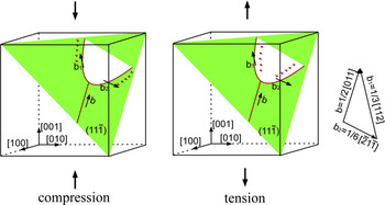
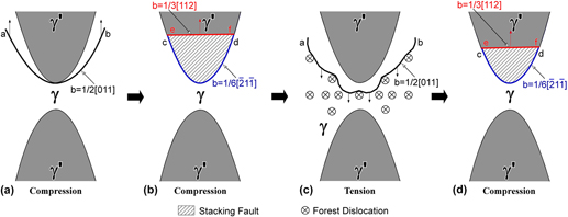
 $\overline 1$] will be pinned in the γ/γ′ interface.Reference Knowles and Chen15,Reference Marchal, Flouriot, Forest and Remy20–Reference Kovarik, Unocic, Li, Sarosi, Shen, Wang and Mills22 The leading dislocation with b = 1/3[112] will move into the γ′ precipitates. These two partial dislocations separated by a stacking fault can move in the opposite directions as shown in Fig. 7. According to the right-hand rule, the movement direction of the two partial dislocations can be determined as marked by the arrows. During compression, the two partial dislocations move away from each other with extension of the stacking fault. In contrast, the two partial dislocations will be close to each other during tension with shrinkage of the stacking fault.
The leading and trailing dislocations act on each other in compression and in tension.

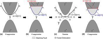
As manifested in Figs. 4 and 6, some dislocations were introduced during TMF compression deformation. These dislocations move in the γ channels and will try to cut into the γ′ cuboids as illustrated in Fig. 8(a). According to our observation, most of the slip dislocations enter the γ′ cuboids by the way of dislocation dissociation following formula (1) in the present TMS-82 superalloy. As stated above, there exists a stacking fault between the leading partial dislocation with b = 1/3[112] and the trailing partial dislocation with b = 1/6[ $\overline 2$1
 $\overline 1$] [Fig. 8(b)]. During tension, a large number of dislocations are introduced in γ channels. Meanwhile, the leading partial dislocation with b = 1/3[112] will move back and combine together with the trailing partial dislocation with b = 1/6[
 $\overline 2$1
 $\overline 1$] to form the original slip dislocation with b = 1/2[011] in the γ matrix [Fig. 8(c)].
The reversible behaviours of stacking faults in compression and in tension. (a) A 1/2[110] dislocation tries to cut into the above γ′ precipitate; (b) 1/2[110] dislocation dissociates to form stacking fault in the above γ′ precipitate; (c) the leading and trailing dislocations recombine and 1/2[110] dislocation cannot cut into the below γ′ precipitate due to the pre-existing dislocations; (d) a 1/2[110] dislocation cut into the above γ′ precipitate and stacking fault forms again.

As stated above, the formation and disappearance of stacking faults is related to the movement of partial dislocations. The activation of the {111}<112> slip system is sensitive to the Schmid factor. The calculation method for the Schmid factor is as follows:
 $${\rm{\lambda }} = \cos \varphi \cdot \cos {\rm{\psi }}\quad {\rm{,}}$$
where λ stands for the Schmid factor,  $\varphi$ stands for the angle between the slip plane normal and the applied stress, and Ψ stands for the angle between the slip direction and the applied stress.
For applying stress in the <001> orientation of a fcc crystal, the twelve {111}<112> slip systems are all stressed. The Schmid factors of all the possible leading partial dislocations and the resolved shear stress (RSS) along the Burgers vector directions both in compression and in tension are all calculated and listed in Table I.
Schmid factors and RSS in all the possible directions.

In practice, to form a stacking fault, it is necessary for the RSS to be large enough to drive the leading partial dislocation. During compression, the shear directions along 1/3[112], 1/3[ $\overline 1$1
 $\overline 2$], 1/3[
 $\overline 1\,$
 $\overline 1$2], and 1/3[1
 $\overline 1\,$
 $\overline 2$] all have a high Schmid factor of 0.47 (λ = 0.47). The RSS (about 216 MPa) is much higher than the critically resolved shear stress (CRSS; about 200 MPaReference Nita, Lagerpusch and Nembach23) and is sufficient to drive the partial dislocation to move. Thus, the stacking faults associated with motion of these partial dislocations will occur in the γ′ cuboids [Fig. 8(b)]. During tension, the CRSS (320 MPaReference Nita, Lagerpusch and Nembach23) for driving the partial dislocations to move along these directions is lower than the RSS (about 444 MPa), however, the stacking faults cannot be found to form (Fig. 5). As revealed by TEM observation, a large amount of dislocations were produced in the γ matrix (Fig. 5) due to the factor that the CRSS for {111}<110> shear is just around 35 MPa.Reference Nita, Lagerpusch and Nembach23 On the other hand, the partial dislocations, which help to form stacking faults in compression, move back to form the perfect dislocation with b = 1/2[011] [following Eq. (1)]. By increasing the tensile stress, the perfect dislocation will try to enter another γ′ cuboid through the γ matrix. This moving perfect dislocation will interact with numerous dislocations in γ phase and be stopped there [Fig. 8(c)]. That is to say, the dislocation with b = 1/2[011] cannot enter other γ′ precipitates to form a new stacking fault. During the following compression, the dislocation with b = 1/2[011] will move back in the γ matrix channel and reenter the γ′ cuboid with appearance of superlattice stacking faults [Figs. 6 and 8(d)].
Cao et al.Reference Cao, Beyerlein, Addessio, Sencer, Trujillo, Cerreta and Gray24 reported the criteria for a widening or narrowing stacking fault configuration. The condition that the force on the leading partial dislocation is higher than that on the trailing one is advantageous to the expansion of a stacking fault. In compression, for the dislocation with b = 1/2[011], the leading partial 1/3[112] owns a higher Schmid factor, leading to a widening stacking fault. However, in tension, the force for the trailing partial is higher, producing a narrowing stacking fault. It is in excellent agreement with the experimental results.
B. Appearance and disappearance of dislocations during TMF cycling
As confirmed with the help of TEM observation, the specimen is free of dislocations in γ channels before testing [Fig. 3(b)]. Now the γ′ phases are fully coherent with the γ phases but with slightly different lattice parameters.Reference Ott and Mughrabi25 Thus, there is a coherency in the strain field around the γ′ cuboids in the γ/γ′ structure. Due to the strengthening from this coherent strain field, a large compressive stress is needed for the first compression. With the gradual introduction of dislocations into γ or γ′ phases, the strain field around the γ′ cuboids is changed by the disturbance from the existing dislocations. Thus, the elastic property of the material varies with the generation and motion of dislocations. After the first stress relaxation, there are a lot of stacking faults in the γ′ cuboids and dislocations in γ channels [Figs. 4(a) and 4(b)]. Macroscopically, the stress for keeping a constant strain (0.64% in the present study) decreases.
During the tensile plastic deformation, large amounts of dislocations were produced (Fig. 5). After the subsequent hold time in compression, most of the dislocations generated from the tensile plastic deformation disappeared (Fig. 6). Since the specimen was kept for 1 h at a high temperature of 900 °C, it is reasonable to assume that the dislocations disappear due to annealing. During the subsequent tensile deformation in tension plus the next hold time in compression, the above process (i.e., dislocation generation and dislocation annihilation) will be repeated again.
V. CONCLUSIONS
In conclusion, the formation process of stacking faults has been studied here, and their reversible behavior has been studied in detail. Several conclusions can be drawn from the following list.
(1) The shears of γ′ particles by 1/3<112> partial dislocations confer stacking faults. These 1/3<112> dislocations result from the decomposition of 1/2<110> matrix dislocations.
(2) The reversible movement of stacking faults under compression and tension depends strongly upon the loading orientation during TMF cycling. Stacking faults occur under compression with respect to their disappearance under tension. The driving force for the glide of the leading dislocations is large enough but not under tension in the context of that there exist a large number of dislocations in γ channels.
(3) The repeating process of generation and annihilation of dislocations is associated with the TMF cycling, in which plastic deformation and stress relaxation occur.
ACKNOWLEDGMENTS
This work was supported by the National Natural Science Foundation of China (Grant Nos. 50971078, 51071096, and 51271097), Shandong Province Natural Science Foundation (Grant No. ZR2010EM009), and China Postdoctoral Science Foundation (special grade, Grant No. 201003630).