I. INTRODUCTION
In the last decade, the structural applications of magnesium alloys were greatly improved by multiple means. Reference Li, Kui, Li, Du, Li, Ma and Shi1,Reference Yuan, Kui, Zhang, Li, Li, Li, Ma and Shi2 Since the icosahedral quasicrystalline phase (I-phase) was found in magnesium alloys, a new approach to higher strengths and ductility was established. Reference Hua, Kato and Yuan3–Reference Luo and Zhang5 Due to the special quasi-periodical structure, the quasicrystalline phase has high hardness, high elastic modular, and low surface energy, which could obviously increase the strength and plasticity of the alloy. The chemical composition of the I-phase is Mg3Zn6RE and the I-phase exists stably in Mg–Zn–RE alloys (the rare earth element RE could be Y, Gd, Er, Dy, and Ho) with the atomic ratio of the Zn/RE of 6. Reference Yong, Yuan and Lu6,Reference Wan, Yang and Chen7 During thermo-mechanical processes (forge, hot rolling or extrusion), the I-phase could be crashed and dispersed in the alloy which leads to better strengthening effect. Moreover, fine I-phase particles could precipitate during the thermo-mechanical processes, which may enhance the strengthening effect. Reference Hua, Kato and Yuan3,Reference Yuan, Yong and Ding8–Reference Singh, Osawa and Somekawa12 After thermo-mechanical processes, heat treatment (350–400 °C) will also cause the precipitation of I-phase. Reference Hua, Yuan, Yuan, Chen, Ding and Wang13 Thus, Mg–Zn–RE alloys reinforced by quasicrystalline have much more potential on structural materials.
As mentioned above, many rare earth elements could be used as the alloying elements to form I-phase. Gd and Y were the most common alloying elements in Mg–RE and Mg–Zn–RE alloys. In the previous studies, Gd or Y was added individually in Mg–Zn–RE alloys. Besides, the phase transformation between I-phase and W-phase during the deformation process at high temperature is unknown. In the present paper, Gd and Y were added to the alloy together and the microstructure and precipitation behavior during deformation were studied, and the transient phase between I-phase and W′-phase was also discussed.
II. EXPERIMENTAL
The alloy for this study had the nominal composition of Mg–3.7Zn–0.3Y–0.3Gd (in at.%). The ingot was prepared by conventional gravity casting with high purity metals in a steel crucible. All melting and casting procedures were under the protection of the shielding gas of Ar-0.05% CH2FCF3. Zn was added to the melt at the temperature of 750 °C. After the Zn melted, the melt was heated to 800 °C, then Y and Gd were added. After stirring, drossing, and adding filter, the melt was carried out with the crucible and directly chilled into water.
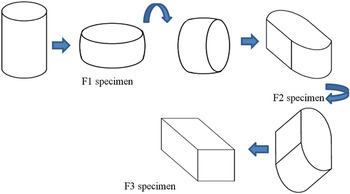
The as-cast alloy was examined by multiple means, including chemical composition, mechanical property test, differential scanning calorimetry (DSC), x-ray diffraction (XRD), and scanning electron microscope (SEM) observation. The ingot was cut into cylinder specimens for forging, with the dimension of 60 × Φ40 mm. The specimens were preheated to 400 °C for 1 h in a muffle furnace and forged one pass with the reduction of 50%. The specimens in this status were designated as F1 (forged one pass). Then the F1 specimens were carried back to the furnace and heated at 440 °C for 4 h as the solution treatment. After solution treatment, the specimens were forged on the other two dimensions with the reduction of 50%, and the specimens were designated as F2 and F3 (totally forged two and three passes, respectively), the forging process was indicated by a schematic drawing in Fig. 1. As the compressions were complete, the specimens were chilled in water. After each forging pass, tensile strength and elongation of these specimens were tested.
Forging process schematic drawing.

The specimens for microstructure and TEM observations were cut from the middle of the forged specimens. The TEM specimens were obtained with wire-electrode cutting, and then followed by mechanical thinning, twin jet thinning, and ion milling. The specimens were observed in a JEOL-2010 microscope (Tokyo, Japan).
III. RESULTS AND DISCUSSION
A. Microstructure and phase compositions of as-cast alloy
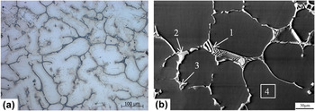
The microstructure observation of the as-cast alloy is shown in Fig. 2, including optical micrograph (OM) and SEM micrographs. The alloy had dendritic structure with the dendritic spacing of 30–60 μm, as shown in Fig. 2(a). Ribbon shaped second phases were mainly distributed on the grain boundaries and between the secondary dendrite arms. Some lamellar eutectics and bulk-like second phases were located at the end of the ribbons and the triangular grain boundaries. Secondary-precipitated phases in which the contrast was gray were found along the second phases. A part of the ribbon second phases distributed between the dendrite arms were discontinuous. Because of the coarse microstructure, the alloy shows mediocre mechanical property. The tensile strength of the as-cast alloy was 201 MPa, with the elongation of 3%. According to the microstructure of the as-cast alloy, the solidification process alloy could be deduced approximately. Because the ingot was 100 mm in diameter, the cooling speed could not be very high. The α-Mg crystallized in the melt first, then grown up to dendrites and kept coarsening. The liquid phase which was rich in alloying elements was squeezed to the grain boundaries and the intermediate regions of the dendritic arms. A cubic phase named W-phase (Mg3Y2Zn3) whose melting point was about 485 °C crystallized in the liquid first and formed eutectic structure and ribbon like second phases, this process consumed most rare earth elements. Then, the peritectic reaction
 ${\rm{W}} + {\rm{Liquid}}_{{\rm{Zn}}\;{\rm{rich}}} \buildrel {448\;^\circ {\rm{C}}} \over \longrightarrow {\rm{I}}$
happened, a large proportion of the W-phase turned to I-phase.
Reference Shao, Varisani and Fan14
The rest of the zinc dissolved into the basis near the I-phase and precipitated as the temperature fell, which might be the precipitations caused the gray contrast in the OM observation.
OM and SEM micrographs of as-cast alloy (a) OM micrograph and (b) SEM micrograph with EDS sampling points.

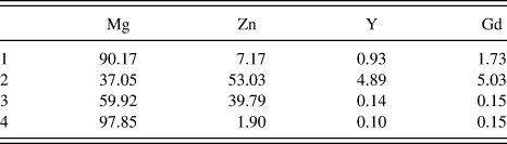
Figure 2(b) shows the SEM image of the as-cast alloy with the EDS sampling points, and the energy dispersive spectrometer (EDS) results are shown in Table I. The phases were clearly observed in a high magnification SEM image. All eutectics and irregular bulk phases were protuberant from the α-Mg basis. This may be suggested that the phases had higher hardness or better corrosion resistance than the basis, thus the basis took more reduction in mechanical polishing, or got more weight loss in corrosion, which made the phases protuberant. The lamellar phase marked by arrow 1 and the bulk phase marked by arrow 2 were I-phase, because the Zn/RE atomic ratios of these phases measured by EDS are 4:1 and 5:1, respectively. This SEM image was collected by a backscattered electron sensor, the contrast of which could be affected by the atomic number of the phases. The phase indicated by arrow 3 had darker contrast which meant it was a different phase. The EDS result shown that it was Mg–Zn binary phase, which might be formed at the end of the solidification. Besides, the element content of the basis (area 4) was also measured by EDS. The result shown that about half of the alloying elements were dissolved in the basis. According to the binary phase diagrams, the maximum solid solubility of Zn, Y, and Gd in magnesium are 2.6, 3.4, and 4.5, respectively, which means that there were still solute solubility for the alloying elements. Thus, solution treatment was available which could make the alloy supersaturated.
EDS results (at.%) for the sampling points in Fig. 2(b).

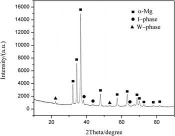
Figure 3 shows the XRD pattern of the as-cast alloy. The existence of three phases was identified by their PDF cards, which were α-Mg basis, icosahedral I-phase, and cubic W-phase. According to Ref. Reference Shao, Varisani and Fan14, when the Zn:RE atomic ratio is 6:1, there will be only I-phase in the alloy in equilibrium state, and when the ratio is lower than 6:1, the W-phase will emerge in the alloy. But in the present alloy, the Zn:RE ratio was a bit higher than 6:1 and the W-phase still existed in this alloy. This might be related to the solidification process mentioned above. Liquid phase which was rich in alloying elements was squeezed to the grain boundaries and W-phase crystallized first which consumed most rare earth elements. Because the cooling speed was not very fast, the rest of the liquid phase which was rich in Zn could be remained for a while, and it would be squeezed away from the W-phases just crystallized as the grains and dendrites grown. Besides, zinc has larger diffusion rate than yttrium and gadolinium, the existing time of the Zn rich liquid phase was long, many Zn could be dissolved into the basis. These influences above might cause the lack of liquid phase and hinder the peritectic reaction. As the reaction failed to complete, the W-phase was remained till the ingot was completely cool.
XRD pattern of as-cast alloy.

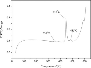
According to the DSC curve presented in Fig. 4, three endothermic peaks were observed. The first peak started at 350 °C, the peak area and peak height were low, which might refer to tiny amount of Mg–Zn binary phases. These Mg–Zn phases consisted of two parts, one was the Mg–Zn irregular bulk marked by arrow 3 in Fig. 2(b) and the other might be the secondary-precipitated phases in the optical micrograph. Because the amount of the Mg–Zn bulk was too few, the size of the secondary-precipitation was too small (even the SEM could not observed it clearly). The Mg–Zn phase was not identified in the XRD pattern and only be found in the DSC curve. The second peak located at 447 °C was the inverse peritectic reaction temperature where I-phase will decompose to W-phase and liquid phase. The third peak which was at 485 °C was the melting temperature of the W-phase. Though there was another peak located at around 580 °C, that temperature was too high for magnesium alloy, so it was not investigated in detail.
DSC curve of as-cast alloy.

B. Effect of hot forge and solution treatment on microstructure
The quasicrystal phase has good stability at high temperature. Homogenization treatment for the as-cast alloy had less effect on the re-dissolution of the I-phase. But the supersaturated solid solution was needed in precipitation process (hot deformation and aging treatment), so the second phases needed to be dissolved as possible. To reach this goal, the alloy was forged one pass before the solid solution treatment. This was aimed to crash the ribbon phases and eutectic structures and made the second phase particles distribute evenly. The specific surface area of the phases would increase; the dislocations and recrystallization grain boundaries formed during the compression would enhance the short circuit diffusion, which might accelerate the decomposition of the second phases. Besides, magnesium alloys with quasicrystal phase have good formability, which could be deformed without being homogenized first. Reference Kim, Bae and Kim10 Thus, the as-cast specimens were forged one pass first, and then the solid solution treatments were carried out. Because the decomposition of I-phase would produce Zn rich liquid phase which might cause over burning, the DSC curve suggested that the temperature of the solid solution should not higher than 447 °C to prevent over burning.
For the subsequent forging experiments, the original ingot was cut to specimens of 40 mm in diameter and 60 mm in height. Magnesium alloy had poor deformability at room temperature because there was only basal slip system at this temperature. To increase the plasticity of the alloy when forging, the specimens need to be heated to activate the prismatic and conical slip systems. Thus the specimens were preheated to 400 °C for 1 h, then forged one pass and chilled into water, named F1 specimen.
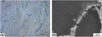
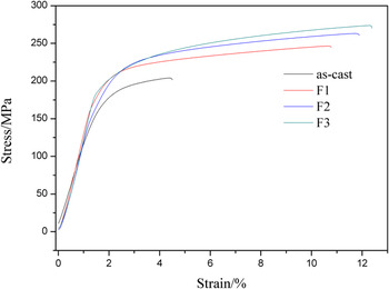
Figures 5(a) and 5(b) show the OM and SEM images of the specimen forged one pass, respectively. It shows a typical forging microstructure. The dendrites and phases were flattened along the forging direction. Though the I-phase had higher hardness than the basis, but it was also a brittle phase, the bending moment during the deformation would fracture the I-phases which were anisometric. Thus, the ribbon phase and eutectic structures were crushed into particles with sharp edges, but the irregular bulk phases did not change obviously. Because the amount of deformation was limited, the particles were not scattered in the basis evenly and still distributed as lines. Besides, micron scale precipitations emerged along the big particles increased after deformation. Partial recrystallization happened in the alloy which made the grain size uneven. The regions which were free of precipitations were nonrecrystallized grains, and the regions full of precipitations had finer grains. This indicated that the precipitations could enhance the recrystallization and impede the growth of the recrystallization grains. The tensile strength of F1 specimen was 246 MPa, with the elongation of 10%. The strengthening effect caused by finer recrystallization grain size and precipitations was the main reason for the increment of the mechanical property.
OM and SEM micrographs of F1 specimen: (a) OM micrograph and (b) SEM micrograph.

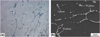
According to the DSC curve and the experience of the solid solution treatment, the temperature of the solid solution treatment was set to 440 °C and the heating time was 4 h. After the solution treatment, the microstructure changed obviously, as shown in Figs. 6(a) and 6(b). The precipitations could not stick the grain boundaries any longer, and the grains grown observably until they reached the broken ribbons. The precipitations in the grains were remained, and the regions near the broken ribbons also had fine precipitations. This had shown that the big particles dissolved a bit during the heat treatment, and some alloying elements might diffuse into the precipitation free zone and precipitated. Besides, phase transformation had happened on some big particles. EDS results for the sampling points marked in Fig. 6(b) indicated that a part of the broken particles transformed to W-phase, as the Zn:RE ratios of which were close to 3:2, other particles were I-phase.
OM and SEM micrographs of solid-soluted F1 specimen. (a) OM and (b) SEM.

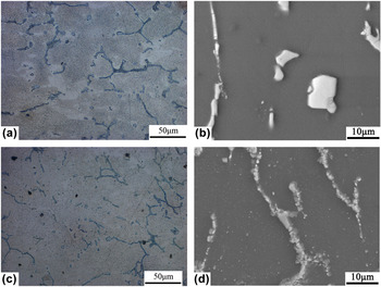
Then, the specimens were forged two passes, between each pass, the specimens were rotated 90°, the OM and SEM micrographs are shown in Figs. 7(a)–7(d). Plenty of precipitations emerged in the grains and the volume of precipitation free zone decreased obviously, especially the 3F specimen. This could be considered as the precipitations during the deformation process, and the precipitations were positively related to the amount of deformation. Figures 7(b) and 7(d) show the SEM micrographs of the 2F and 3F specimens respectively. The ribbon phases and bulk phases were crushed by compression in the 2F specimen. EDS results shown that the ribbon phase and irregularly granulated phase indicated with two arrows were I-phase, and the bulk phase in the middle was Mg–RE phase. The broken I-phase had sharp fracture surface, which means the I-phase was a brittle phase. In the 3F specimen, granulation happened on the broken I-phase. This may be due to the third forge pass. The specimen was compressed on the other dimension, the broken I-phase particles impacted each other, and the grains milled the sharp edge of the particles. Besides, the amount of the precipitations in the grains increased. The mechanical properties also increased with the forging passes. The tensile strength of 2F and 3F specimens was 262 and 273 MPa, respectively, and the elongations of both were about 11%. The stress–strain curves are shown in Fig. 8. It indicated that the recrystallization and precipitation in the alloys were enhanced by the forging processes. The recrystallization grain boundaries and precipitations could impede the sliding of the dislocations, which could improve the tensile strength. Besides, dislocations could bypass the crushed ribbons, instead of pilling-up near the phases and initiating microcracks. Intergranular slip was more active because the recrystallization grains were fine. Therefore, the elongations of the forged specimens were better.
OM and SEM micrographs of F2 and F3 specimens. (a), (b) Micrograph of F2 specimen, (c), (d) micrograph of F3 specimen.

Stress–strain curves of as-cast, F1, F2, and F3 alloys.

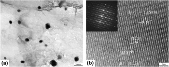
The precipitations could not be observed clearly, thus the TEM and high resolution TEM (HRTEM) observations were carried out to characterize the morphology of the precipitations. The TEM morphology of the precipitations in the 3F specimen is shown in Fig. 9(a). The rhomboid particles with the size of 100–150 nm were identified as W′-phase by HRTEM and selected area diffraction pattern (SADP) shown in Fig. 9(b). The W′-phase has FCC structure which was the same to the W-phase in the Mg–Zn–RE alloys, but the lattice parameter of W′-phase (a = 2.05 nm) was about three times as that of W-phase (a = 0.6848 nm). The incident direction of Fig. 9(b) was
 $B = \left[ {11\bar 2} \right]$
, and the interplanar spacing of
 $\left[ {1\bar 11} \right]$
measured from the picture is 1.15 nm, which was close to the theoretical data 1.18 nm. This might be due to the rare earth alloying elements, i.e., yttrium and gadolinium in this study, and the W-phase in the reference only contained yttrium as the rare earth element, so the lattice parameter might have some difference.
TEM and HRTEM images of F3 specimen. (a) Precipitations in F3 specimen. (b) HRTEM image of W′-phase with SADP.

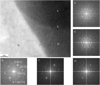
HRTEM observation with fast Fourier transform (FFT) images on the interface between the basis and one of the spherical particles is presented in Fig. 10. The incident direction was perpendicular to the 5-fold symmetry planar of the quasicrystalline. The FFT images marked by capital letters are corresponding to the areas which were tagged with the same letters. Area B was the Mg basis, according to the FFT image, the observation direction was
 ${\left[ {01\bar 11} \right]_{{\rm{Mg}}}}$
. The interface between the basis and the particle was very smooth and shows some orientation relationships. A phase which had lamellar structure was labeled as area C. The lamellae had different contrasts and had no periodicity, which made them hard to measure and calibrate. The FFT image of area C shown that this lamellar phase had coplanar relationship with
 ${\left( {01\bar 11} \right)_{{\rm{Mg}}}}$
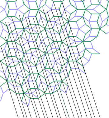
. But the main diffraction patterns lying on the X-axis were the reflection of the nonperiodic lamellar structure. The patterns had no periodicity either, but the distances between each pattern were corresponding to the Fibonacci sequence, which were also accord with one of the 5-fold axis patterns of the quasicrystal as shown in the FFT image of areas D and E in Fig. 10. This indicated that the lamellar structure has quasi-periodicity, and the lamellae were parallel to one of the 5-fold axis of the quasicrystal. The lamellar phase had orientation relationships with both Mg-basis and quasicrystal and shown both crystalline and quasi-crystalline characteristics. Figure 11 shows the sketch map of area D on microstructure. It had shown the relationship between the quasicrystal and the lamellar structure phase. The quasicrystal was presented as the Penrose tilling, which contained two kinds of rhombuses as its structure cells. The side length of the two rhombuses was same, and the vertex angles of the big and small rhombuses were 72° and 36°, respectively. By arranging these rhombuses, the Penrose tilling with 5-fold symmetry was presented. The lamellar structure of area C in the HRTEM image was also indicated with the black lines in the sketch map. Besides the parallel relationship between the line and the 5-fold axis, the interlamellar spacing of the lines was also observable. Two interlamellar spacing of the lamellar structure was calculated from the sketch map, which was 0.59 and 0.36, where the side length of the rhombuses was set to 1. Moreover, other relationship between the Penrose tilling and the lamellar structure was found, as the big interlamellar spacing of 0.59 was the height of the small rhombuses, and the sum of the two interlamellar spacings of 0.59 + 0.36 was the height of the big rhombuses. The permutation of the lamellar structure showed no periodicity. Considered with the relationships between the two structures and the FFT images, the lamellar structure should be quasi-periodic structure. Therefore, it might be a transient phase between I-phase and W-phase (or W′-phase). The W-phase was stable on high temperature, and the I-phase may be transformed into W-phase on high temperature (over 410 °C), thus, the lamellar phase should be a transient phase of the transformation process of I-phase to W-phase.
HRTEM image with FFT patterns of the interface of a quasicrystal and lamellar structure particle.

Structural schematic diagram of quasicrystal and lamellar structure.

IV. CONCLUSION
-
(1) The microstructure and phase composition of as-cast Mg–3.7Zn–0.3Y–0.3Gd were studied. The as-cast alloy has dendritic structure and consists of α-Mg, I-phase, W-phase, and Mg–Zn precipitations.
-
(2) The alloy was compressed one pass, then annealed at 440 °C for 4 h and followed by two passes of compression. The strip like second phases were crushed during the deformation and partially dissolved. New precipitation particles emerged all around the alloys.
-
(3) The tensile strengths and elongations of the specimens increased with the forging processes. Recrystallization and precipitation were the primary strengthening mechanism.
-
(4) The precipitations are W′-phase and I-phase particles and were observed by HRTEM. A particle with I-phase and quasi-periodicity lamellar structure phase was studied, and the transformation process of I-phase to W-phase was discussed.