Introduction
Magnesium alloy has attracted significant attention in various modern industries, greatly due to its low density, high strength-to-density ratio, and good shock absorption, etc. [Reference Li, Li, Wang, Zhang, Cheng, Liang and Zhang1, Reference Wang, Liu, Zhai and Zou2, Reference Wang, Liu, Wu, Chen and Zhang3, Reference Zhou, Xiong, Jia, Tan, Cheng and Liu4]. However, the poor corrosion resistance of magnesium alloy with more negative self-corrosion potential has always restricted its applications [Reference Jin, Hao, Peng and Chu5, Reference Pan, Yang and Chen6].
Surface treatments or coatings, such as anodization, physical vapor deposition, chemical vapor deposition, electroless plating, and chemical conversion technologies, are important methods to improve the corrosion resistance of magnesium alloy [Reference Turan, Sun and Akgul7, Reference Fan, Gao, Zhao, Yang, Guo and Jiang8, Reference Wang, Liu, Dou, Zhang and Jiang9]. Electroless plating is widely used in various fields since it could form uniform coatings and small pinholes, deposits on nonconductors, and has certain special properties with electromagnetic shielding and conductibility [Reference Czagány, Baumli and Kaptay10, Reference Moosaie and Panahi-Kalus11]. Meanwhile, the low cost and environmental characteristic of electroless plating have attracted many researchers to study. Electroless nickel-phosphorus (Ni–P) alloy coatings possess high microindentation hardness and outstanding corrosion resistance since they are stable in alkalis, salts, seawater, and organic acids [Reference Nasirmanesh and Mohammadi12, Reference Phelan, Han, Lopez-Bezanilla, Krogstad, Gim, Rong, Zhang, Parshall, Zheng, Cooper, Feygenson, Yang and Chen13]. Although they have tremendous advantages, electroless Ni–P alloy coatings still have some inevitable obstacles, for instance, large internal stress of coatings and low bond strength between coatings and magnesium alloy substrate, which did not meet the requirements of actual engineering applications. Furthermore, when the content of phosphorus (P) exceeds 10 wt%, the amorphous structure of Ni–P alloy coatings is obtained and offers extraordinary corrosion resistance owing to no dislocations, grain boundaries, or other crystalline defects. Hence, our attentions are captured by functionally gradient materials, which are meant for the use as two (or more) materials with different properties. The properties of the coating are optimized with the disappearance of the interfaces by continuously changing the composition and structure of these two (or more) materials [Reference Shi, Cao, Song, Liu and Atrens14, Reference Zhu, Xiong, Tang and Zuo15, Reference Li16]. With the low-to-high phosphorus contents, the electroless Ni–P alloy gradient coatings could not only increase bonding strength and reduce internal stress but also evidently improve corrosion resistance for amorphous structure.
Chemical conversion coatings, act as low soluble physical barrier between metal surface and environments, are often used as primer for a further protective layer [Reference Li, Zhu, Liu, Liu and Ma17]. As people pay more and more attention to environmental protection, some new chemical conversion coatings that are less harmful to the environment have been developed, such as phosphate-permanganate, rare earth compounds, and stannate conversion film. Among them, the stannate conversion film has raised our concern [Reference Shao, Ming and Zhang18, Reference Zhang, Jiang, Li, Jiang and Lian19].
The activity of magnesium alloy is so high that the direct electroless plating Ni–P gradient coating will cause the weak adhesion, which could lead to the coating fall off easily or produce various defects. Therefore, the magnesium alloy must be properly pretreated. The stannate conversion film could well protect magnesium alloy substrate from corroding and provide a good base for the subsequent electroless Ni–P gradient coating [Reference Wang, Yang, Ma, Zhang and Hao20]. Single Ni–P gradient coating or stannate conversion film has been researched. However, the study about the corrosion resistance of Ni–P gradient coating on stannate conversion film on the surface of AZ91D alloy has been seldom reported [Reference Rosalbino and Scavino21].
Results and discussion
Morphologies and formation mechanism of stannate conversion film
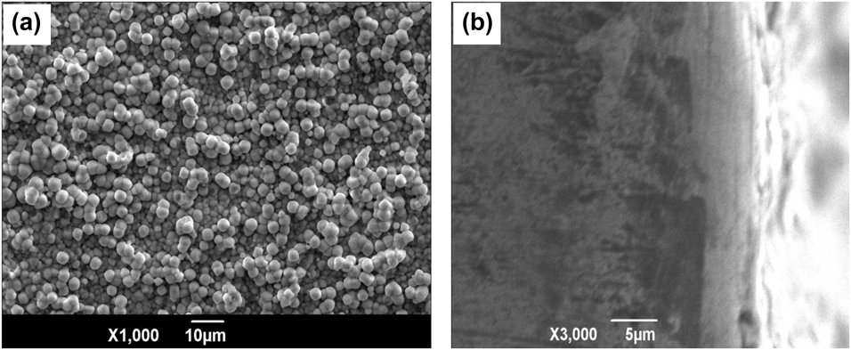
Obviously, the dense stannate conversion film was composed of uniform and fine spherical particles with pores, which provided a more ideal roughened surface for subsequent electroless Ni–P coating as shown in Fig. 1(a). The stannate conversion film with the thickness of 5 μm was in good agreement with the AZ91D alloy substrate, as shown in Fig. 1(b).
The (a) surface and (b) cross-sectional morphologies of stannate conversion film.

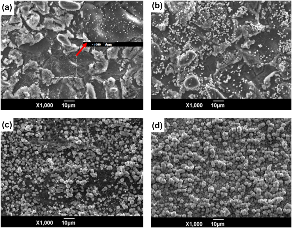
The formation process of the stannate conversion film could be divided into two stages, namely, nucleation (0–5 min) included nucleation—dissolution—remodeling nucleus and periodic growth (5–60 min) contained nucleation—growth—dissolution. The SEM images of the stannate conversion film treated for different times (i) 2 min, (ii) 10 min, (iii) 30 min, and (iv) 50 min are displayed in Fig. 2. In the initial stage at 2 min, a large number of critical nuclei were formed on AZ91D alloy substrate where there were still many regions with nuclei free. The pre-existing nuclei grew up as the reaction carried out to 10 min, which was limited by the physical collision of the nuclei with each other in the plating bath. In addition, after 2 min of the stannate conversion reaction, the regions with free nuclei were dotted with small nuclei which would grow to a final size combined with the surrounding nuclei. The nuclei with a certain size contacted with the ambient nuclei to stop the growth, and the stannate conversion reaction occurred in the areas remained either no nuclei or scattered tiny nuclei as shown in Fig. 2(c). Finally, as observed from Fig. 2(d), the surface of sample was completely covered with the accumulation of spherical particles, indicating that the stannate conversion film was successfully prepared on the AZ91D alloy substrate [Reference Bagalà, Lamastra, Kaciulis, Mezzi and Montesperelli22].
The SEM images of stannate conversion film treated for different times (a) 2 min, (b) 10 min, (c) 30 min, and (d) 50 min.

Morphologies and compositions of electroless Ni–P gradient coating on stannate conversion film
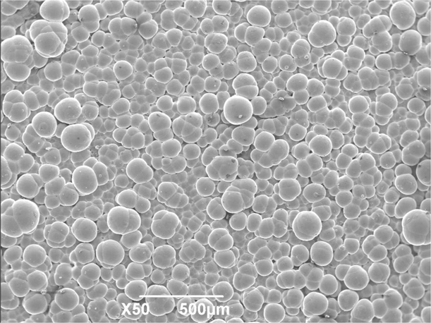
It can be seen from Fig. 3 that the Ni–P gradient coating with typical cell morphology was entirely covered on stannate conversion film accompanying dense structure with no obvious defects.
The surface morphology of Ni–P gradient coating on stannate conversion film.

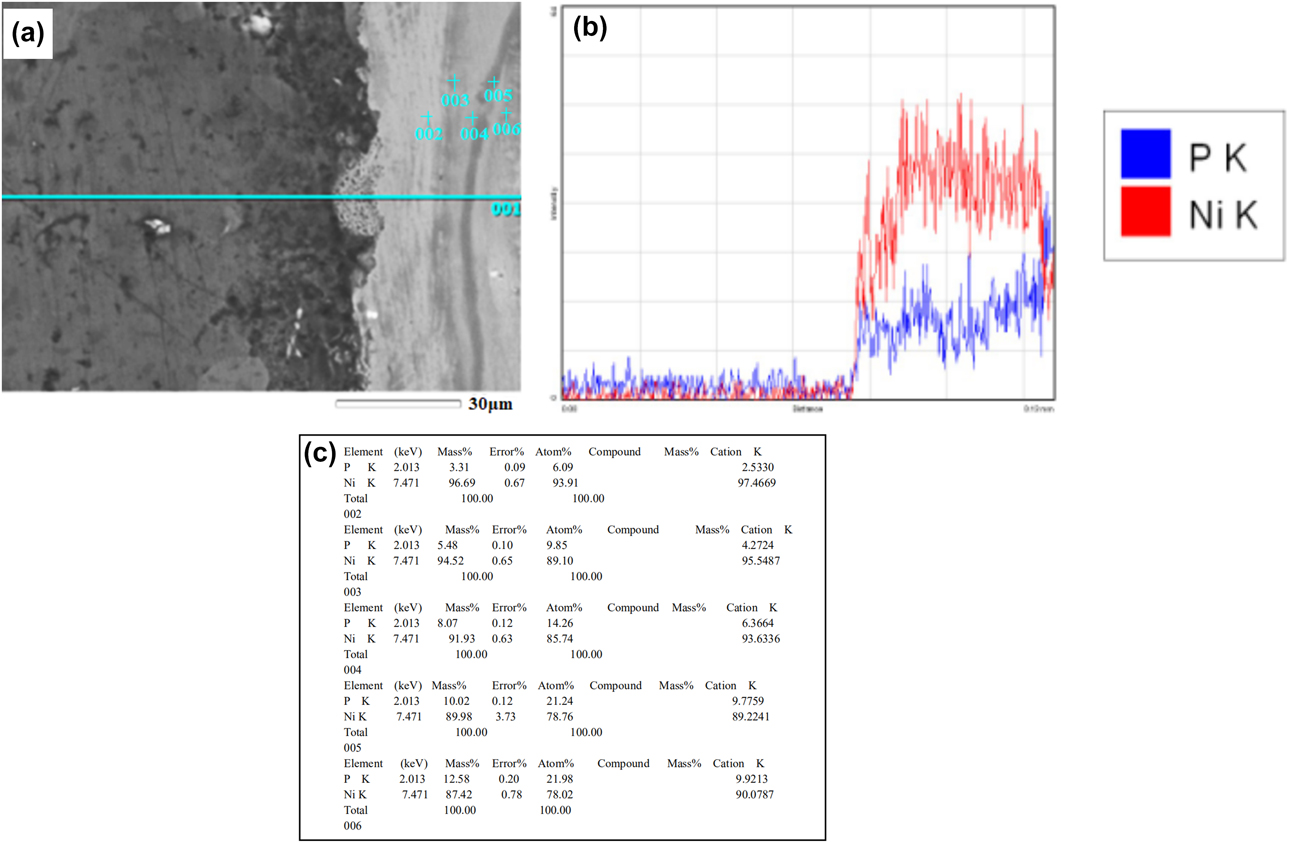
The cross-sectional morphology and energy dispersive spectroscope (EDS) spectrogram of electroless Ni–P gradient coating are shown in Fig. 4, and 002, 003, 004, 005, and 006 marked in the map separately represent different electroless Ni–P coatings along the direction from the AZ91D alloy substrate to Ni–P gradient coating. As observed from Fig. 4(a), the Ni–P gradient coating with no obvious defects like gaps and cracks was uniformly deposited on AZ91D alloy substrate. In addition, the total thickness of Ni–P gradient coating was about 40 μm. It is noticeable that the P content gradually increases along the direction from the AZ91D alloy substrate to the Ni–P gradient coating as shown in Fig. 4(b). The crystal structures of Ni–P gradient coating are related to P content. When P content is less than 5 wt%, the structure of Ni–P alloy is the supersaturated replacement solid solution of P atom in Ni lattice. When P content is 6–9 wt%, the Ni–P alloy is a microcrystalline with the transitional stage from crystalline to amorphous. And when P content is 10 wt% or more, the Ni–P alloy is the typical structure of amorphous [Reference Lin, Lin, Lin and Lai23, Reference Yin and Chen24, Reference Sidhu, Prakash and Agrawal25]. It could conclude that with increasing P content, the structures roughly present crystalline → microcrystalline → amorphous. It is seen from Fig. 4(c) that P content was separately 3.31, 5.48, 8.07, 10.02, and 12.58 wt%, suggesting that P content appeared gradient changing from inside to outside of the Ni–P gradient coating. The above-mentioned results are associated with the increment of the sodium phosphate content in the plating bath which might be due to the limited reaction area of sample, and the proportional distributed ion in reaction as a result  ${{\rm{H}}_2}{\rm{PO}}_2^ -$ ion in plating bath was correspondingly increased proportionally and the reduction of Ni2+ ion accordingly decreases as [Reference Wang, Liu, Dou, Zhang and Jiang9],
 $${\rm{N}}{{\rm{i}}^{2 + }} + {{\rm{H}}_2}{\rm{PO}}_2^ - + {{\rm{H}}_2}{\rm{O}} \to {{\rm{H}}_3}{\rm{PO}}_3^ - + {\rm{Ni}} + 2{{\rm{H}}^ + } + {{\rm{e}}^ - }\quad .$$
The cross-sectional morphology and EDS spectrogram of Ni–P gradient coating, (a) cross-sectional morphology (b) and (c) EDS spectrogram.

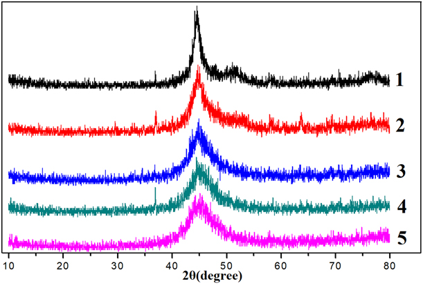
The X-ray diffraction spectra of electroless Ni–P gradient coating are shown in Fig. 5. Five lines represented five kinds of electroless Ni–P coating with different P contents from inside to outside, respectively (electroless coatings 1, 2, 3, 4, and 5). It is noteworthy that the diffraction peak of electroless Ni–P coating shifted a larger angle and became gradually broadening from the inner layer to the outer layer. It might be attributed to the smaller P atoms that dissolve into the face-centered cubic of Ni metal, leading to the shrinkage of the Ni lattice to balance the Bragg equation. As the P content increases, the lattice distortion becomes large enough to break the crystal lattice, causing amorphous structure. Specifically, the P atoms with low content could sufficiently diffuse into the Ni lattice. And the codeposited P content is so high that hinders the diffusion of Ni element even nucleation of grains, resulting in the formation of a smaller-sized amorphous phase [Reference Fan, Gao, Zhao, Yang, Guo and Jiang8, Reference Wang, Liu, Dou, Zhang and Jiang9, Reference Liu, Viejo, Guo, Glenday and Liu26]. What is more, it is found that the change of electroless Ni–P coating from sharp peak to typical steamed bread peak, further demonstrating that the structures roughly presented crystalline → microcrystalline → amorphous along the increasing thickness of the coating.
The X-ray diffraction spectra of electroless Ni–P coatings numbered 1, 2, 3, 4, and 5.

Adhesion of Ni–P gradient coating on stannate conversion film
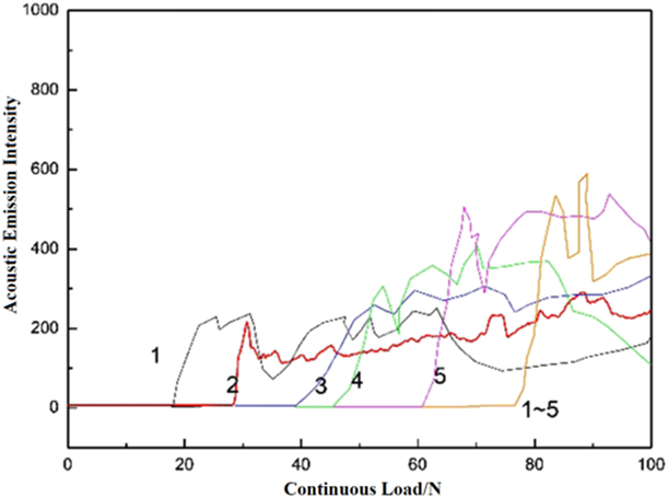
The curve scratches with the acoustic emission signal-load of Ni–P gradient coating indicated that the sound signal suddenly enhanced from loading to unloading as shown in Fig. 6 (cited the Figs. 3–5), and the greater the critical load, the better the adhesion between Ni–P gradient coating and AZ91D alloy substrate coated with stannate conversion film. With its whole critical load of 79.65 N, the single critical load of electroless Ni–P coatings 1, 2, 3, 4, and 5 was 19.82 N, 30.22 N, 39.85 N, 46.31 N, and 62.55 N, respectively. In other words, the Ni–P gradient coating subjected to an external force with larger than 79.65 N would appear balling-up, skin off, or other phenomena. Additionally, it is found that adhesion of the whole Ni–P gradient coating was significantly stronger than the single layer due to a high degree of interface matching of Ni–P gradient coating with composition compatibility and the outermost amorphous structure without defect.
The curve scratches of electroless Ni–P gradient coatings numbered 1, 2, 3, 4, and 5.

Corrosion resistance of Ni–P gradient coating on stannate conversion film
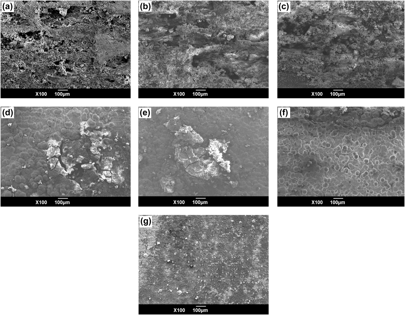
The corrosion morphologies of stannate conversion film, electroless Ni–P coatings 1, 2, 3, 4, and 5, and the whole Ni–P gradient coating immersed in 3.5 wt% NaCl solution for 72 h are shown in Fig. 7. The corrosion morphologies of stannate conversion film, which initially might be the pitting corrosion, gradually damaged locally and appeared serious corrosion pits with prolonged corrosion time as shown in Fig. 7(a). Compared with the stannate conversion film, the Ni–P gradient coating with clearer outline was more mildly corroded, demonstrating that the corrosion resistance of Ni–P gradient coating was more excellent, which occurred an obvious improvement by increasing P content as shown in Figs. 7(a)–7(g). It is attributed to the corrosion resistance of Ni–P gradient coating with low P content is weaker since it is crystal structure. The Ni–P gradient coating with more than 10 wt% P content, which is amorphous with grain boundary free leading to the reduced corrosion path, and more uniform composition is not easy to form corrosion microbatteries in the corrosive medium. Moreover, a dense and stable passivation film of Ni–P intermediate complex is formed due to the P enrichment caused by accelerated active dissolution of Ni atom on account of preferentially adsorbed Cl− ion on the nodule boundary of the Ni–P gradient coating. What is more, the passivation film could have quick self-healing although it damages.
Corrosion morphologies of samples coated with various coatings immersed for 72 h (a) stannate conversion film, (b)–(g) electroless Ni–P coatings numbered 1, 2, 3, 4, and 5, and Ni–P gradient coating.

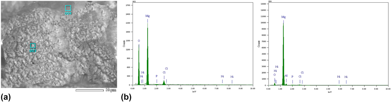
The corrosion morphology and EDS spectrogram of electroless Ni–P gradient coating on stannate conversion film immersed for 72 h are displayed in Fig. 8. It can be found that the Ni and P elements of Ni–P gradient coating still with cellular structure were detected in corrosive production, demonstrating that the gradient structure played a significant role in an interface protection by effectively inhibiting corrosive medium to deeply permeate.
The corrosion morphology and EDS spectrogram of Ni–P gradient coating on stannate conversion film immersed for 72 h (a) corrosion morphology and (b) EDS spectrogram.

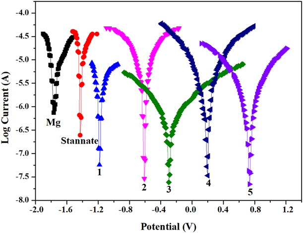
The polarization curves of the substrate, stannate conversion film, and electroless Ni–P gradient coating measured in 3.5 wt% NaCl solution are shown in Fig. 9. Notably, after stannate conversion treatment, the first, second, third, fourth, and fifth electroless Ni–P plating, the self-corrosion potential was increased to −1.42 V, −1.20 V, −0.58 V, −0.28 V, 0.23 V, and 0.75 V respectively. It could be concluded that the self-corrosion potential of AZ91D alloy substrate treated with diverse treatment overall shifted gradually to a nobler direction, and the corrosion resistance of Ni–P gradient coating was better than the stannate conversion film. Moreover, with the gradually increased P content from the first to fifth layers, the corrosion resistance of Ni–P gradient coating was improved little by little with reduced galvanic corrosion tendency of AZ91D alloy substrate contacting with other materials [Reference Ma, Wu, Ning, Xia and Liu27]. This is ascribed to the electrochemical potential of the outer layer of Ni–P gradient coating and is more positive than the inner layer so that it is not conducive to forming a corrosive battery of a large cathode and small anode. Furthermore, when the outmost layer is attacked, the inner layer of Ni–P gradient coating which is regarded as the stack of multilayer material acts as a cathode to protect the AZ91D alloy substrate from corrosion by corrosive media.
The polarization curves of the substrate, stannate conversion film, and electroless Ni–P coatings numbered 1, 2, 3, 4, and 5.

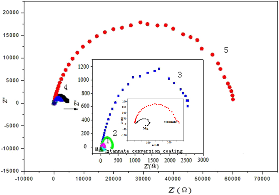
The electrochemical impedance spectroscopy (EIS) of the substrate, stannate conversion film, and electroless Ni–P gradient coating in 3.5 wt% NaCl solution are presented in Fig. 10. Distinctly, it can be seen that every Ni–P gradient coating was all only one capacitance loop in the high frequency region, accordingly the larger capacitance loop radius, and the better corrosion resistance. Therefore, it is evident that the corrosion resistance obtained was improved in the order AZ91D alloy substrate < stannate conversion film < the Ni–P gradient coating. The reaction resistance of Ni–P gradient coating from the first to fifth layers was increased, and the corrosion resistance was more excellent [Reference Ambat and Zhou28].
The electrochemical impedance spectroscopy (EIS) of the substrate, stannate conversion film, and electroless Ni–P coatings numbered 1, 2, 3, 4, and 5.

The AZ91D alloy was performed by stannate conversion and then electroless Ni–P plating. The dense and continuous stannate conversion film was approximately spherical particles, which provided electroless Ni–P coatings for a rough surface and possessed certain corrosion resistance. The reason why Ni–P coating can further improve the corrosion resistance of AZ91D alloy may be that anions in the bath penetrated into the pores of stannate conversion film and reacted with AZ91D alloy to form precipitate with high chemical stability to block the pores, which made stannate conversion film more complete and compact. The precipitate not only effectively prevents corrosive media from corroding AZ91D alloy substrate but also enhances the isolation of Ni–P gradient coating to corrosive environmental media, which is benefit to improve the corrosion resistance of Ni–P gradient coating. Then electroless Ni–P gradient coating could be well deposited on stannate conversion film with certain roughness to form uniform continual coating. Additionally, the stannate conversion film as the intermediate layer could also reduce electrode potential difference between Ni–P gradient coating and AZ91D alloy substrate to hinder the formation of direct corrosion microbattery. Besides, contacting with corrosive media, the corrosion of the Ni–P gradient coating was slowed down and even stopped because the coating first happened active dissolution as a result leaving phosphorus-rich layer to form nickel phosphide passivation film; as the higher the P content, the faster the formation of passivation film. In this study, the AZ91D alloy coated with the Ni–P gradient coating on stannate conversion film distinctly enhances the corrosion resistance.
Conclusions
(1) The Ni–P gradient coating/stannate conversion film was successfully deposited on AZ91D alloy substrate by electroless plating. With different sodium hypophosphite concentrations in the bath, the P content of Ni–P gradient coating was gradually increased from the inside to the outside.
(2) The Ni–P gradient coating with typical cellular morphologies was covered completely on dense stannate conversion film, which was no obvious defect. The thickness of Ni–P gradient coating was about 40 μm. Meanwhile, with increasing P content along the direction of AZ91D alloy substrate to the outer coating, the structures of Ni–P gradient coating presented roughly crystalline → microcrystalline → amorphous.
(3) The polarization curves and the EIS result demonstrated the stannate conversion film and the Ni–P gradient coating were all significantly improved the corrosion resistance of AZ91D alloy substrate. The corrosion resistance of Ni–P gradient coating was better than stannate conversion film and was gradually enhanced with increasing P content.
Experimental section
Coating preparation
The pretreatment process of AZ91D alloy substrate was as follows. Sample polishing (silica water sandpaper to 2000 #) → Sample ultrasonic degreasing (acetone) → Alkali cleaning (80 g/L sodium hydroxide, 25 g/L sodium phosphate, 40 °C, 20 min) → Acid pickling (60 g/L phosphoric acid, 15 g/L potassium fluoride, 50 °C, 100 s) → Surface activating (120 mL hydrofluoric acid, 50 g/L potassium fluoride) → Preparation for the stannate conversion film and electroless Ni–P gradient coatings. Every procedure must be rinsed by the distilled water in order to ensure the next step to implement successfully. The AZ91D alloy with a size of 25 × 15 × 10 mm was applied as the substrate in the following stannate conversion with sodium stannate as major salt, and sodium hydroxide and sodium pyrophosphate as additives. To obtain the Ni–P gradient coating, a five-step acidic nickel coating bath was used by changing concentration of sodium hypophosphite varied as 5, 10, 22, 46, and 60 g/L in the bath (also containing 75 g/L Nickel sulfate, 32 g/L Sodium citrate, 20 g/L Ammonium bifluoride, 8 g/L Hydrogen fluoride, 10 g/L Thiourea, 65 °C, 45 min, pH 5.0–6.0). Accordingly, the electroless coatings numbered 1, 2, 3, 4, and 5 in the paper represented five kinds of electroless Ni–P coating with different P contents, respectively.
Characterizations and tests
The surface and cross-sectional morphologies and compositions of the composite coatings were investigated by scanning electron microscopy (SEM, JSM-6390A, JEOL Ltd., Tokyo, Japan) equipped with an EDS). The crystal phases of the Ni–P gradient coating were analyzed by X-ray diffractometer (XRD-7000, shimadzu, Tokyo, Japan). The adhesion of each layer of electroless Ni–P gradient coating was measured by a scratch tester (WS-2005, Beijing meitu environmental instruments Co., Ltd., Beijing, China). The sample coated with electroless Ni–P coating was loaded from 0.1 N with 5 mm/min to 100 N with 50 mm/min at a distance of 4 mm. During the test, the load was the critical load as the coating appeared fall off. Electrochemical property was tested by an electrochemical analyzer (Chenhua Instruments Co., Ltd., Shanghai, China) which used a three-electrode system. The polarization curve measurement began to work after the samples were immersed in 3.5 wt% NaCl aqueous solution for about 20 min with a sweep rate of 1 mV/s.
Acknowledgments
The work was supported by the National Natural Science Foundation of China (50172023) and the Shaanxi Industrial Science and Technology Research (2014K08-09) and the National College Students Innovation Training Program (201810704006).