I. INTRODUCTION
Alloy tool steel is widely used in the engineering community, such as the Cr12MoV steel, a kind of alloy tool steel being used for manufacturing the molds, wear resistant components, cutting tools, etc. To improve the performance of the alloy tool steel, the quenching process is used frequently during the manufacturing process. The microstructure for the as-quenched alloy tool steel is martensite, which results in that the alloy tool steel possesses lager surface hardness. However, the deformation resistant capability for the as-quenched alloy tool steel is reduced owing to the existence of the larger residual stress, e.g., the slide valve pair including the valve spool and the valve bush will be locked owing to the slow deformation caused by the release of residual stress. As well known, the heat treatment process is adopted to relieve the residual stress to improve the deformation resistant capability. But this processing process will reduce the surface hardness of the alloy tool steel severely. So it will bring great engineering value to study a new residual stress relieving technology improving the performance of the alloy tool steel.
Vibratory stress relief (VSR) is a widely used residual stress relieving technology, which has many advantages such as better effect, energy saving, and shorter processing time. The VSR in resonant frequencies was introduced by McGoldrick and Saunders. Reference McGoldrick and Saunders1 They applied mechanical vibrations at 10–30 Hz to eliminate the residual stresses in the casting and welding structures and claimed that the VSR could decrease the residual stresses. Walker et al. Reference Walker, Waddell and Johnston2 relieved the residual stresses in a low-alloy steel EN3b specimen with the exciting-frequency of 100 Hz and found that the residual stress relief rate was about 40%. Sun et al. Reference Sun, Sun and Wang3,Reference Sun, Sun and Wang4 relieved the residual stresses in the marine shafting and welded plates of low alloy high strength steel. They claimed that the residual stress decreased by about 50%.
Although the VSR technology has been extensively studied, Reference McGoldrick and Saunders1–Reference Sun, Sun and Wang4 the limitation of the VSR technology can be drawn as follows. The speed-adjustable motor is adopted as the exciter and the vibration frequency is lower than 200 Hz, which results in that the VSR is confined to eliminate the residual stress in the large workpiece. Meanwhile, the optional vibration mode for the VSR is fewer, which results in that the local residual stress in the large workpiece cannot be effectively eliminated by the VSR technology. Furthermore, the exciter is too big to be installed with a small workpiece. As a result, it can be concluded that the residual stress in the small workpiece cannot be effectively eliminated by the VSR technology as well. Considering the shortcoming of the conventional VSR technology, the high-frequency VSR technology Reference He, Ren, Chen and Fai5–Reference He, Gu, Zheng and Shen8 had been put forward. The electromagnetic vibrator was adopted as the exciter in the high-frequency VSR technology, in which the small workpieces could be easily installed on the vibration table to be excited. In addition, local residual stress in the larger workpiece can be effectively eliminated since the impact effect can be imposed on the local surface area of the larger workpiece by the vibration table. To reveal the mechanism of the high-frequency VSR, the relationship among crystal particles inside the workpiece was considered as a multiple-degree-of-freedom system. Reference He, Ren, Chen and Fai5–Reference Wang and He7 When the external vibration frequency equals to a certain resonant frequency of this system, the crystal particles will be back to its original equilibrium position. In this case, the dislocations and the residual stress in the crystal materials can be reduced by the high-frequency VSR. To verify the rationality of theoretical analysis, the dislocations distribution in the crystal materials before and after the high-frequency VSR was carried out using the transmission electron microscope (TEM) technology. Reference Wang and He7 Based on the TEM photos, Reference Wang and He7 it can be concluded that the dislocation density can be reduced during the high-frequency VSR. The findings confirm that the high-frequency vibration will affect the evolution of the dislocation density. However, the evolution rule of the dislocation density during the high-frequency vibration process cannot be revealed in the multiple-degree-of-freedom system. So how to establish a dislocation density evolution model can reveal the underlying mechanism of the high-frequency VSR and it is the key issue in the research field of the high-frequency VSR. Even though the high-frequency VSR is promising, the application of the high-frequency VSR is also limited due to the indistinctive effect of relieving residual stresses in related to the lower output displacement amplitude of the electromagnetic vibrator. Furthermore, the mechanism of the high-frequency VSR technology is still unclear. So the mechanism of the high-frequency VSR and the corresponding experimental studies must be conducted to promote the wide application of the high-frequency VSR.
The high-frequency VSR experiments were conducted based on the electromagnetic vibrator and the amplitude boost in this study. In addition, the high-frequency vibration plasticity model was developed based on the thermal activation theory to reveal the mechanism of the high-frequency VSR.
II. MECHANISM OF HIGH-FREQUENCY VSR
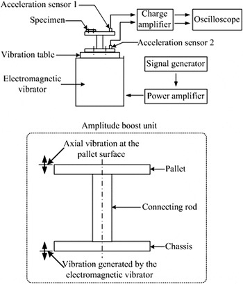
The schematic of the high-frequency VSR device designed for this study is shown in Fig. 1. It mainly consists of an electromagnetic vibrator capable of generating high-frequency vibration and an amplitude boost unit used for installing the specimen to be excited by larger amplitude. The signal generator controls the exciting-frequency, while two acceleration sensors are implemented to measure the input displacement amplitude of the electromagnetic vibrator and the output displacement amplitude of the amplitude boost unit directly applied on the specimen. An amplitude boost unit made of aluminum alloy 2A12 Reference He, Gu, Zheng and Shen8 is used to boost the high-frequency vibration. The amplitude boost unit, shown in Fig. 1, is composed of a pallet, a connecting rod, and a chassis. Since the amplitude boost unit itself functions as the working table, the vibration at the pallet surface plays a critical role in the high-frequency VSR. The amplitude boost unit was excited by the electromagnetic vibrator in an axial direction as shown in Fig. 1. And the specimen could be installed on the pallet to be excited by larger amplitude according to the vibration theory. In this case, the dislocation motion can be easily activated with the help of the high-frequency vibration energy, which results in that the shear plastic deformation can easily happen inside the specimen. In other words, the high-frequency vibration plasticity effect will happen during the high-frequency VSR. As a result, the residual stress in the specimen can be relieved when the specimen is exposed on the high-frequency vibration field.
The schematic of the high-frequency VSR device.

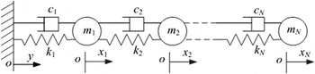
The mechanism of the high-frequency VSR is discussed based on the microcosmic dynamic theory. The relationship of particles inside the specimen is regarded as a multiple-degree-of-freedom system Reference Wang and He7 based on the microcosmic dynamic theory. In Fig. 2, the particles are equivalent to the lumped mass elements m i (i = 1, 2, …, N, here N is the number of degree of freedom of this system), and the interaction between each particle is equivalent to the effects of the elastic element with stiffness coefficient k i and the damping element with damping coefficient c i . The differential equation of the multiple-degree-of-freedom system of the particles can be obtained as Reference Thomson and Dahleh9
 $${\bf {M}}\ddot{\bf {x}} + {\bf {C}} \dot{\bf {x}} + {\bf {Kx}} = {\bf {CE}} \dot{{\bf {y}}} + {\bf {KEy}}\quad ,$$
where M, C, and K are the mass, damping, and stiffness matrix, respectively;
 $\ddot {\bf {x}}$
,
 $\dot {\bf {x}}$
, and x are the acceleration, velocity, and displacement vector of the particles, respectively;
 $\dot {\bf {y}}$
and y are the velocity and displacement vectors of the external exciting, respectively; E is the N × 1 column vector in which each element is 1. When the mass element m
p
(p = 1, 2, …, N) is excited, the displacement admittance of any mass element m
l
(l = 1, 2, …, N) can be obtained as
Reference Thomson and Dahleh9
 $${H_{lp}}\left( f \right) = \sum\limits_{r = 1}^N {{1 \over {{K_{er}}\left[ {1 - \bar f_r^2 + j2{\zeta _r}{{\bar f}_r}} \right]}}} \quad ,$$
where
 ${\bar f_r}$
is the rth order modal frequency ratio and
 ${\bar f_r} = f/{f_r}$
, f is the exciting-frequency, f
r
is the rth order modal frequency,
 ${\zeta _r}$
is the rth order modal damping factor, K
er
is the rth order modal equivalent stiffness, and f
nr
is the rth order resonant frequency and
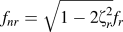 ${f_{nr}} = \sqrt {1 - 2\zeta _r^2} {f_r}$
. If the external exciting-frequency f equals to the rth order resonant frequency f
nr
of the system, the response function H
lp
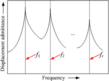
(f) will get a peak value as shown in Fig. 3, which results in that the vibration amplitude of the particles is the largest. In other words, the particles will get the largest vibration energy at this time, which implies that the dynamic stress applied on the particles is largest. In this case, it will promote the motion of the dislocations inside the particles. So the purpose of eliminating the residual stresses in the specimen by the high-frequency VSR can be achieved.
Model of the multiple-degree-of-freedom system of the particles inside the specimen.

Displacement admittance of the multiple-degree-of-freedom system of the particles.

III. EXPERIMENTAL DETAILS
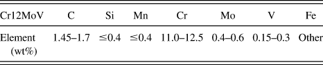
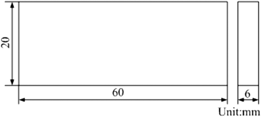
A batch of platelike specimens was prepared from the Cr12MoV steel (GB/T 1299-2000), whose nominal chemical composition is given in Table I. The size of the specimens was 60 × 20 × 6 mm as shown in Fig. 4, whose initial residual stresses were induced by 950 °C oil quenching with the time of 3 min.
Nominal chemical composition of the Cr12MoV steel (wt%).

Map of a Cr12MoV steel quenched specimen.

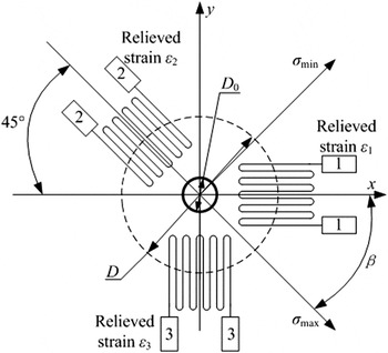
The residual stresses in the specimen were evaluated by the hole-drilling method according to the Standard ASTM E 837-08. 10 The three-element clockwise rosette used for measuring the relieved strains can be shown in Fig. 5. 10 In Fig. 5, D is the diameter of the gage circle; D 0 is the diameter of the drilled hole; the strain grid 1 and the strain grid 3 coincide with the x-axes and the y-axes, respectively, while the angle between the strain grid 2 and the x-axes is 45°; σmax and σmin are the maximum principal stress and the minimum principal stress, respectively; β is the clockwise angle from the x-axes (strain grid 1) to the maximum principal stress direction; the relieved strain ε1 and the relieved strain ε3 coincide with the x-axes and the y-axes, respectively, while the angle between the relieved strain ε2 and the y-axes is 45°. According to the Standard ASTM E 837-08, the x axial and y axial residual stresses at the measured points can be given as 10
 $$\left\{ \matrix{ {\sigma _x} = \left( {{E \over {2\left( {1 + \nu } \right)\bar a}} + {E \over {2\bar b}}} \right){\varepsilon _1} + \left( {{E \over {2\left( {1 + \nu } \right)\bar a}} - {E \over {2\bar b}}} \right){\varepsilon _3} \hfill \cr {\sigma _y} = \left( {{E \over {2\left( {1 + \nu } \right)\bar a}} - {E \over {2\bar b}}} \right){\varepsilon _1} + \left( {{E \over {2\left( {1 + \nu } \right)\bar a}} + {E \over {2\bar b}}} \right){\varepsilon _3} \hfill \cr} \right.\quad ,$$
where ε is the relieved strain surrounding the drilled hole at the measured point, ν is the Poisson's ratio, E is the Young's modulus,
 $\bar a$
is the calibration constant for isotropic stresses,
 $\bar b$
is the calibration constant for shear stress, σ
x
is the x axial residual stress, and σ
y
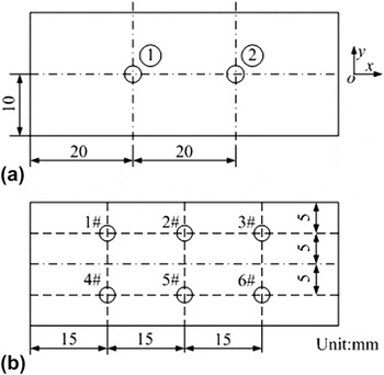
is the y axial residual stress. To compare the residual stresses in the same specimen before and after the high-frequency VSR, two measured points were selected as shown in Fig. 6(a). The interval space of the two measured points was 20 mm, and they were distributed symmetrically on the either side of center line. The residual stresses in the same specimen were supposed to be uniform, which indicates that the residual stresses at the two measured points were the same. The measured point 1 was used to evaluate the residual stresses in the specimens before the high-frequency VSR, and the measured point 2 was used to evaluate the residual stresses in the specimens after the high-frequency VSR.
Schematic of a three-element clockwise rosette used for measuring the relieved strains.

(a) Distribution map of the two measured points for the residual stresses; (b) distribution map of the six testing points for the surface hardness.

The related experimental setup for measuring the residual stress mainly consisted of a ZDL-II residual stress measuring setup, a YE2538 static strainmeter capable of measuring three relieved strains in three different directions, and a TJ120-1.5-
 $\phi$
1.5 three-element clockwise strain rosette. The diameter and depth of the drilled hole are both 2 mm. According to the Standard ASTM E 837-08,
10
the calibration constant for isotropic stresses
 $\bar a$
and the calibration constant for shear stresses
 $\bar b$
are, respectively, selected as 0.192 and 0.482. Submitting the relieved strains into Eq. (3), the x axial and y axial residual stress at the measured points can be obtained to evaluate the effect of the high-frequency VSR.
The surface hardness for the specimen before and after the high-frequency VSR was tested according to the standard of Rockwell hardness test. 11 The Rockwell apparatus used to test the surface hardness of the specimen was a HR-150A (Shanghai Lunjie Mechanical Electrical Instrument Co. Ltd., Shanghai, China). To compare the surface hardness in the same specimen before and after the high-frequency VSR, six testing points were selected as shown in Fig. 6(b). 1#–3# testing points were divided as the first group, and 4#–6# testing points were divided as the second group. Each group of testing points was distributed symmetrically on the vertical line of horizontal center line. The space between the horizontal center line and each group of testing points was 5 mm, and the interval space of each testing point in the same group was 15 mm. The testing points in the first group were used to test the surface hardness for the specimens before the high-frequency VSR, and the testing points in the second group were used to test the surface hardness for the specimens after the high-frequency VSR.
To study the effects of the high-frequency VSR process on grain boundaries, metallographies of the specimen were performed before and after the high-frequency VSR using a LEICA DM6000 optical microscope (OM; LEICA Co., Wetzlar, Germany). To reduce the effects of cutting process on the metallurgical properties of the specimen, fine electro-discharge wire cutting process was used to cut the specimen. After cutting the specimen, the etching process for the specimen was carried out with a weak solution of nitric acid and alcohol for 20 s. And then metallography photos were taken and analyzed using the LEICA DM6000 OM.
The dislocation density for the Cr12MoV steel quenched specimen was tested by using the nondestructive x-ray diffraction (XRD) method, in which the mechanical state of the specimen can be maintained compared to the TEM method. In this study, an X'Pert PRO polycrystalline x-ray diffractometer with Cu Kα radiation (PANalytical Co., Almelo, The Netherlands) was used for the dislocation density testing. The x-ray tube voltage and current are 40 kV and 40 mA, respectively. The scanning angle 2θ used in this study is 35°–145° with a step of 0.015°, in which the diffractions of (110), (200), (211), (220), (310), and (222) can be covered. The dislocation density was evaluated using the Williamson–Hall (WH) method. Reference Gay, Hirsch and Kelly12–Reference Williamson, Smallman and Harwell16
IV. RESULTS AND DISCUSSIONS
A. Effect of high-frequency vibration on residual stress
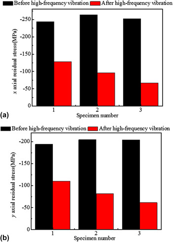
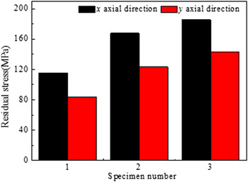
The residual stresses of the three specimens along x and y axial directions before and after the high-frequency VSR are shown in Figs. 7(a) and 7(b), respectively. Figures 7(a) and 7(b) show that the residual stresses are negative which indicates that the residual stresses in the specimens are compressive stresses. It can be easily seen from Fig. 7 that the high-frequency VSR has good effects on eliminating residual stress. The amplitudes applied on the 1# specimen, 2# specimen, and 3# specimen are, respectively, 6, 8, and 10 μm. The x and y axial residual stress relieving values for the 1# specimen, 2# specimen, and 3# specimen can be shown in Fig. 8. The residual stress relieving value can be obtained by the following equation:
 $$\Delta {\sigma _{x,y}} = {\rm{After}}\left( {{\sigma _{x,y}}} \right) - {\rm{Before}}\left( {{\sigma _{x,y}}} \right)\quad ,$$
in which After(σ x,y ) is the residual stress in the specimen after the high-frequency VSR and Before(σ x,y ) is the residual stress in the specimen before the high-frequency VSR.
Residual stress evaluation results of (a) x axial residual stress and (b) y axial residual stress.

Residual stress relieving values.

It can be found from Fig. 8 that the x axial and y axial residual stress relieving values can be improved by increasing the amplitude applied on the specimen. The high-frequency vibration energy imposed into the specimen can be improved by increasing the amplitude. Under this condition, the dislocations in the specimen can be more easily activated with higher vibration energy imposed into the specimen. In other words, the dislocations can more easily glide along the slip plane, which results in that the shear plastic deformation can be more easily occur in the specimen. So the effect of the high-frequency VSR can be improved by increasing the amplitude applied on the specimen as shown in Fig. 8.
B. Effect of high-frequency vibration on surface hardness
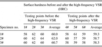
Table II shows that the surface hardness for the as-quenched Cr12MoV steel before and after the high-frequency VSR are HRC (Rockwell hardness) 60–62 and HRC 58–60, respectively. Apparently, the surface hardness for the Cr12MoV steel specimens changes slightly before and after the high-frequency VSR. By comparing Fig. 8 with Table II, it can be found that the effect of the high-frequency VSR could be improved with the higher amplitude, but the surface hardness for the Cr12MoV steel specimens remains almost the same when increasing the amplitude. Thus, the high-frequency VSR is hopeful to be adopted as a kind of residual stress relieving technology.
Surface hardness of the three Cr12MoV steel quenched specimens before and after the high-frequency VSR (HRC).

C. Effect of high-frequency vibration on microstructure
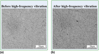
The cryptocrystalline martensite base Cr12MoV steel grain boundaries are clear in Fig. 9, in which the vibration amplitude applied on the specimen was 10 μm. It shows no considerable changes in the grain size of the specimen before and after the high-frequency VSR. It can be resulted that the stress relieving process has not changed the grain size of the specimen. Under this condition, it can be concluded that the residual stress relieving is not induced by the microstructure change; meanwhile, the only mechanism of the high-frequency VSR may be the dislocations motion. Furthermore, the high-frequency VSR will not considerably change the grain size of the specimen, which results in that the surface hardness of the specimen changes slightly before and after the high-frequency VSR as listed in Table II.
OM photos of the Cr12MoV steel quenched specimen: (a) before the high-frequency VSR; (b) after the high-frequency VSR.

D. Effect of high-frequency vibration on dislocation density
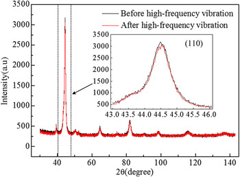
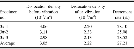
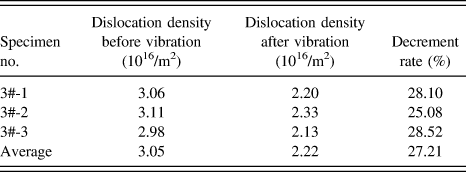
To reveal the variation tendency of the dislocation density for the specimen exposed in the high-frequency vibration field, the XRD of the Cr12MoV steel quenched 3# specimen before and after the high-frequency VSR was carried out in this study. The XRD diffraction patterns for the Cr12MoV steel 3# specimen before and after the high-frequency VSR are shown in Fig. 10. It can be found from Fig. 10 that the full width at half maximum in the crystal face (110) has been changed with the help of the high-frequency vibration, which implies that the dislocation density for the Cr12MoV steel quenched specimen has been changed. The dislocation densities for the three Cr12MoV steel specimens are listed in Table III using the WH method, in which the three specimens were vibrated with the same vibration amplitude of 10 μm. The average dislocation densities for the three specimens before and after the high-frequency VSR are 3.05 × 10¹⁶ m−2 and 2.22 × 10¹⁶ m−2 with the decrement rate of 27.21% as listed in Table III, which implies that the residual stress relaxation mechanism of the high-frequency VSR is the decrease of the dislocation density owing to the dislocation density evolution process during the high-frequency vibration process as analyzed in Sec. IV. E.
XRD of the Cr12MoV steel quenched specimen.

Dislocation densities for the three Cr12MoV steel quenched specimens.
E. High-frequency vibration plasticity model based on the thermal activation theory
To reveal the underlying mechanism of the high-frequency VSR, the high-frequency vibration plasticity model was proposed based on the thermal activation theory. In continuum constitutive equations, the shear plastic strain rate due to thermally activated dislocation glide is generally represented using the form of Arrhenius equation, which is given as Reference Kocks, Argon and Ashby17,Reference Kocks and Miller18
 $${\dot \gamma ^p} = {\dot \gamma _0}\exp \left( {{{ - \Delta G} \over {kT}}} \right)\quad ,$$
where
 ${\dot \gamma ^p}$
is the shear plastic strain rate,
 ${\dot \gamma _0}$
is the pre-exponential factor and can be regarded as a numerical constant, ΔG is the Gibbs free energy for overcoming an obstacle, k is the Boltzmann constant, and T is the absolute temperature. A useful phenomenological generalization equation of ΔG can be expressed as
Reference Kocks, Argon and Ashby17,Reference Kocks and Miller18
 $$\Delta G = F{\left[ {1 - {{\left( {{{\tau + {\tau _r}} \over {\hat \tau }}} \right)}^p}} \right]^q}\quad ,$$
where F is the total free energy necessary to overcome the obstacle in the absence of eternal applied stress, τ
r
is the resolved value of the residual stresses in the specimen, which is applied on the slip plane, and the exponents p and q are the obstacle distribution parameters with the range of
 $0 \;\lt\; p \;\le\; 1$
and
 $1 \;\le\; q \;\le\; 2$
.
 $\hat \tau$
is an internal variable representing the material prosperity and is called mechanical threshold, which is regarded as the shear strength of the material at absolute zero (0 K) and is also regarded as the maximum glide resistance for dislocation motion.
Reference Argon19
The internal variable
 $\hat \tau$
depends on the total dislocation density ρ, which is usually expressed as
Reference Kocks, Argon and Ashby17,Reference Kocks and Miller18
 $$\hat \tau = {\tau _0} + aGb\sqrt \rho \quad ,$$
where ρ denotes the dislocation density, τ0 is the friction stress and is generated by the crystal lattice, a is a numerical constant, G is the shear modulus, and b is the magnitude of the Burgers vector.
Like every natural processes, the development of total dislocation density consists of two processes. The first one is the increase of dislocation density
 ${\rm{d}}{\rho ^ + }$
due to the dislocation accumulation process, and the second one is the decrease of dislocation density
 ${\rm{d}}{\rho ^ - }$
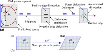
due to the annihilation process taking into account the annihilation of existing dislocations and generated dislocations by Frank-Read source as shown in Fig. 11(a). Assuming that the part of the dislocation line (e.g., the Orowan loop) remains around the forest dislocations while the dislocations cut across the forest dislocation, the increase of dislocation density is given as
Reference Kocks20–Reference Estrin and Mecking22
 $${{{\rm{d}}{\rho ^ + }} \over {{\rm{d}}{\gamma ^p}}} = {k_1}{\rho ^{{1 \mathord{\left/ {\vphantom {1 2}} \right. \kern-\nulldelimiterspace} 2}}}\quad {\rm{,}}$$
and for the second process, the decrease of dislocation density (e.g., the positive edge dislocation encountering with the negative edge dislocation) is given as Reference Kocks20–Reference Estrin and Mecking22
 $${{{\rm{d}}{\rho ^ - }} \over {{\rm{d}}{\gamma ^p}}} = {k_2}\rho \quad ,$$
where the dislocation storage coefficient k 1 is regard as a constant, and the dynamic recovery coefficient k 2 depends on the plastic strain state and the temperature. Combining Eqs. (8) and (9), the total dislocation density can be given as Reference Kocks20–Reference Estrin and Mecking22
 $${{{\rm{d}}\rho } \over {{\rm{d}}{\gamma ^p}}} = {k_1}{\rho ^{{1 \mathord{\left/ {\vphantom {1 2}} \right. \kern-\nulldelimiterspace} 2}}} - {k_2}\rho \quad .$$
The relationship between dislocations evolution process and plastic deformation process: (a) definition of dislocation density. A dislocation segment fixed at two points A and B. A and B are nodes of the dislocation network. b is the Burgers vector; (b) general steps in a plastic deformation process caused by the motion of dislocations. m is the normal direction unit vector of the slip plane, and s is the slip direction unit vector. S1 denotes the step 1 before the dislocation motion, and S2 denotes the step 2 after the dislocation motion.

The residual stress relaxation in the Cr12MoV steel specimen as described in this study is strongly related to the change of the total dislocation density as analyzed in Sec. IV. D. Considering Eq. (10), k 1 and k 2 may change due to the effect of the high-frequency vibration, leading to the change of the dislocation evolution process, which results in that the effect of residual stress relaxation induced by high-frequency VSR is good. Thus, the dislocation evolution process with the help of the high-frequency vibration can be further given as
 $${{{\rm{d}}\rho } \over {{\rm{d}}{\gamma ^p}}} = {k_1}\left( {1 + {\vartheta _{{k_1}}}} \right){\rho ^{{1 \mathord{\left/ {\vphantom {1 2}} \right. \kern-\nulldelimiterspace} 2}}} - {k_2}\left( {1 + {\vartheta _{{k_2}}}} \right)\rho \quad ,$$
where the nondimensional parameters
 ${\vartheta _{{k_1}}}$
and
 ${\vartheta _{{k_2}}}$
are the change ratios of k
1 and k
2 owing to the action of the high-frequency vibration, respectively.
 ${\vartheta _{{k_1}}}$
and
 ${\vartheta _{{k_2}}}$
relate to the additional dislocation accumulation and annihilation induced by the high-frequency vibration, respectively, and the effect of the high-frequency VSR is obviously affected by these two parameters. As shown in Sec. IV. D, it can be found that the dislocation annihilation process has a dominant position than the dislocation accumulation process. In other words, the dislocation density for the specimen can be reduced with the help of the high-frequency vibration. Under this condition, the residual stress can be relieved owing to the shear plastic deformation as shown in Fig. 11(b)
Reference Argon19
caused by the dislocation evolution process as shown in Fig. 11(a). Equations (5)–(11) provide a constitutive model governing the relation between dislocation motion at the microscale and residual stress relaxation at the macroscale. The high-frequency vibration plasticity model reveal the mechanism of the high-frequency VSR can be attributed to the shear plasticity deformation induced by the dislocation density evolution process.
V. CONCLUSIONS
The high-frequency VSR based on the electromagnetic vibrator and the amplitude boost unit was introduced to the same group of Cr12MoV steel quenched specimens. The main conclusions can be drawn as follows:
-
(1) The high-frequency VSR has good effects on eliminating residual stress, and increasing the amplitude applied on the workpiece can improve the effect of the high-frequency VSR.
-
(2) The surface hardness for the three Cr12MoV steel quenched specimens before and after the high-frequency VSR are HRC 60–62 and HRC 58–60, respectively. The surface hardness for the as-quenched Cr12MoV steel is almost the same when increasing the amplitude.
-
(3) Metallographic tests show there are no changes in the grain size of the quenched Cr12MoV steel during the high-frequency VSR, while the average dislocation densities for the three specimens during the high-frequency VSR are 3.05 × 10¹⁶ m−2 and 2.22 × 10¹⁶ m−2 with the decrement rate of 27.21%. The decrease of the dislocation density is the essence of the residual stress relaxation during the high-frequency VSR.
-
(4) The high-frequency vibration plasticity model reveals the mechanism of the high-frequency VSR. The findings confirm that the significant effects of high-frequency vibration on metal plasticity and provide a basis to understand the underlying mechanism of the high-frequency VSR.
ACKNOWLEDGMENTS
This research is sponsored by the high-tech research and development program of China (No. 2013A2041106) and the National Natural Science Foundation of China for Young Scholars (No. 51605303).