I. INTRODUCTION
Multi-way broadband power dividers/combiners are an important part of many microwave systems such as power-combining amplifiers and antenna arrays. Recently, various multi-way power combiners/dividers have been presented at microwave and millimetre-wave frequencies [Reference Song and Xue1–Reference Song and Quan15], such as substrate integrated waveguide power dividers [Reference Eom, Byun and Lee2], rectangular waveguide power dividers [Reference Jiang, Ortiz and Mortazawi4–Reference Becker and Oudghiri6], radial waveguide power dividers [Reference Fathy, Lee and Kalokitis7, Reference Song, Fan and He8], conical power dividers [Reference De Villiers, van der Walt and Meyer9, Reference De Villiers, van der Walt and Meyer10], and coaxial waveguide power dividers [Reference Song and Xue11–Reference Alexanian and York14]. In these designs, waveguide-based broadband power dividers have been widely investigated and used in microwave and millimetre-wave systems because of their low insertion loss, wide bandwidth, and high-power capability. However, the operating bandwidth of the rectangular waveguide is limited by the cutoff frequency and the rectangular waveguide environment is dispersive, which complicates broadband impedance matching over an extended frequency range [Reference Jiang, Ortiz and Mortazawi4–Reference Becker and Oudghiri6]. In the previous studies, the authors presented the broadband ring-cavity power dividers/combiners using probe array that achieved low-loss waveguide-to-probe transition [Reference Song and Xue1, Reference Song, Hu, Xue and Fan3, Reference Song and Quan15]. The designed and measured results indicated that this novel structure has wide bandwidth and low loss.
In this paper, an eight-way ring-cavity power divider using stepped-impedance matching technology has been presented. Compared to the previous work [Reference Song and Xue1, Reference Song, Hu, Xue and Fan3, Reference Song and Quan15], this modified structure can achieve a wider bandwidth by combing the taper with the stepped impedance transformer. The proposed power-dividing structure can not only hold large numbers of power-dividing ports but also can have ultra-wideband (UWB) performance. The use of the stepped-impedance technology makes the modulation easily. A coaxial taper feeding port has been applied into the ring cavity to provide uniform excitation for the multiple-way ring-cavity power divider, and then, excellent amplitude and phase balance of the output ports has been obtained. The network of this eight-way ring-cavity power divider has also been analyzed. The measured results agree with the simulation closely. The design results indicate that this structure has several advantages, such as a wider bandwidth, large numbers of power-dividing ports, excellent input impedance matching, low insertion loss, and good balance of amplitude and phase at output ports.
II. STRUCTURE, ANALYSIS, AND DESIGN
Figure 1 shows the proposed ring-cavity eight-way power combiner/divider. A coaxial taper feeding port has been applied to provide axially symmetric electromagnetic-field excitation for the ring-cavity power divider and to implement good amplitude and phase balance for the power-combining ports, which can also obtain good impedance matching from the coaxial port to the oversized ring cavity. The coaxial taper can be designed according to [Reference Song and Xue1]. The proposed ring-cavity power combiner/divider is terminated by the Sub-Miniature-A (SMA) connector (coaxial port). The power combiner/divider can be divided into three parts: the transition from input SMA connector to the oversized coaxial waveguide, the transition from the oversized waveguide to the ring cavity, and the transition from the ring cavity to the output SMA connector.
Proposed ring-cavity eight-way power divider: (a) sketch of the ring cavities with output ports and (b) structure of the power divider.

In general, the length of the coaxial probes is chosen to be normally about λg/4 to implement impedance matching, where λg is the wavelength at central frequency. However, for the capacitance-loaded coaxial probe, its length is far less than λg/4. As shown in Fig. 1, the length of L 0 should be maintained as about λg/4 to make the outer side of the ring cavity be the short wall. So the width (R − R 0) and height of the ring cavity are kept constant. That is to say, when the number of probes increases greatly, only the perimeter of the ring cavity increases, the section of the ring cavity keeps constant, and the higher-order modes cannot propagate in the ring cavity after an appropriate design. So, this type of power-combining structure is very suitable for large numbers of power-combining ports. The proposed ring power combiner/divider can be constructed and optimized in the three-dimensional electromagnetic simulation tools (such as Ansoft-HFSS), and the optimized structural dimensions of the proposed ring-cavity power combiner/divider can also be obtained.
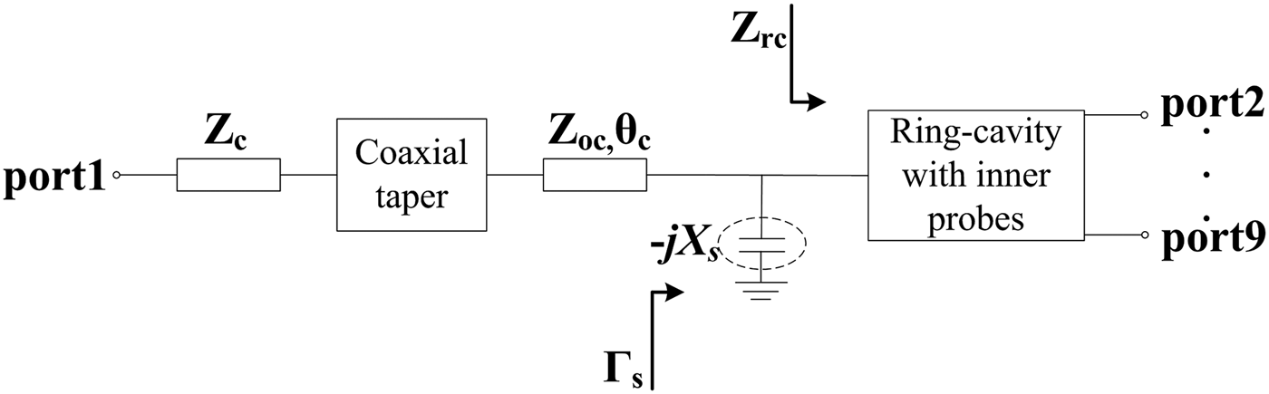
When compared the proposed structure in Fig. 1(b) and the structure in [Reference Song and Xue1], stepped-impedance technology is used between the coaxial taper feeding port and the ring cavity to improve the impedance matching which will broaden the bandwidth. The approximate equivalent circuit of the proposed eight-way ring-cavity power divider is shown in Fig. 2. The stepped discontinuity from the output port of the coaxial taper to the ring cavity is modeled as a capacitive reactance −jX S, which is marked by the dashed line. In the structure of [Reference Song and Xue1], the capacitive reactance X S cannot be modulated when the size of the ring cavity is determined, while in the proposed structure of this paper, X S, could be modulated easily (by modulating the size of L 2 and R s), that means the impedance matching between the coaxial taper feeding port and the ring cavity would be improved.
The approximate equivalent circuit of the proposed power divider.
In the equivalent circuit above, Z rc is the input impedance of the ring cavity with inner probes, Γs is the reflection coefficient of the stepped impedance and ring cavity including the planar probe array, and Z oc is the impedance of the extended coaxial. Based on the transmission-line theory, the reflection coefficient Γs can be given by
 $${\Gamma _s}=\displaystyle{{\left({\left({ - j{X_S}{Z_{rc}}} \right)/\left({ - j{X_S}+{Z_{rc}}} \right)} \right)- {Z_{oc}}} \over {\left({\left({ - j{X_S}{Z_{rc}}} \right)/\left({ - j{X_S}+{Z_{rc}}} \right)} \right)+{Z_{oc}}}}.$$
It can be seen that the reflection coefficient Γs is determined by X S, Z rc, and Z oc. So the adjustability of X S will improve the impedance matching greatly. Figure 3 shows the simulated S 11 at different structural parameters. It can be seen that the stepped-impedance part could improve the impedance match effectively.
The simulated S 11 at different structural parameters: (a) L s and (b) R s.
The characteristics of the proposed structure can be analyzed by the microwave network theory. As it is known, for the n-port lossless reciprocal network, there is
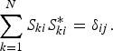 $$\sum\limits_{k=1}^N {{S_{ki}}S_{ki}^\ast }={\delta _{ij}}.$$
If i = j, then δij = 1; if i ≠ j, then δij = 0. That is
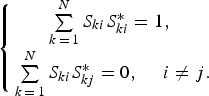 $$\left\{{\matrix{ {\sum\limits_{k\,=\,1}^N {{S_{ki}}S_{ki}^\ast =1\comma \; } } \cr {\sum\limits_{k\,=\,1}^N {{S_{ki}}S_{kj}^\ast =0\comma \; \quad i \ne j.} } \cr } } \right.$$
For the proposed ring-cavity eight-way power combiner/divider in this paper, its structure is axially symmetric. Port 1 is set as the input port, and the last n ports are set as the output ports in turn (shown in Fig. 1(a)). Assuming that the input port is impedance matched, the S-parameter matrix of this kind of axially symmetric power combiner/divider could be given as
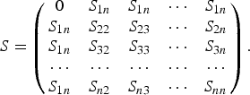 $$S=\left({\matrix{ 0 & {{S_{1n}}} & {{S_{1n}}} & \cdots & {{S_{1n}}} \cr {{S_{1n}}} & {{S_{22}}} & {{S_{23}}} & \cdots & {{S_{2n}}} \cr {{S_{1n}}} & {{S_{32}}} & {{S_{33}}} & \cdots & {{S_{3n}}} \cr \cdots & \cdots & \cdots & \cdots & \cdots \cr {{S_{1n}}} & {{S_{n2}}} & {{S_{n3}}} & \cdots & {{S_{nn}}} \cr } } \right).$$
This is an (n + 1)-order square matrix [Reference Kagan16]. If this structure is lossless, the above matrix would be the unitary matrix. So according to equation (3), there will be
 $${\left\vert {{S_{1n}}} \right\vert ^2}=\displaystyle{1 \over n}\comma \;$$
 $${\left\vert {{S_{1n}}} \right\vert ^2}+{\left\vert {{S_{22}}} \right\vert ^2}+{\left\vert {{S_{32}}} \right\vert ^2}+\cdots+{\left\vert {{S_{n2}}} \right\vert ^2}=1\comma \;$$
 $${S_{1n}}\left({S_{_{22} }^\ast +S_{_{32} }^\ast +\cdots+S_{_{n2} }^\ast } \right)=0.$$
Here, as the structure is axially symmetric, there is
 $$\left\vert {{S_{i\comma j}}} \right\vert =\left\vert {{S_{i\comma n+4 - j}}} \right\vert \comma \; \quad \left\vert {{S_{i\comma j}}} \right\vert =\left\vert {{S_{i+1\comma j+1}}} \right\vert .$$
According to equations (6) and (8), it could be concluded that the return loss of the output port is in correspondence with the isolation of the output port. In general, the isolation of the output port is not equal, but they are all around the average value. So the derivation of this average value can provide a certain reference. It can be given by
 $${\left\vert {{S_{ij}}} \right\vert ^2}=\displaystyle{{n - 1} \over {{n^2}}}\comma \; \quad i \ne 1\comma \; \; i \ne j.$$
As to the proposed ring-cavity eight-way power combiner/divider, n is equal to 8, so the average value of isolation and return loss of the output ports is
 $$10\lg \left({{{\left\vert {{S_{ij}}} \right\vert }^2}} \right)=- 9.6\, {\rm dB}\quad \left({n=8\comma \; \; i \ne 1\comma \; \; i \ne j} \right).$$
Table 1 shows some average values of several different n (n is the number of the output ports). From Table 1, it can be seen that the power divider/combiner designed by this structure (axially symmetric) is not suitable for the power divider/combiner with fewer output ports, as the isolation or the return loss of the output port could not reach the requirement of some systems. But, to the multi-way power divider's design, this issue will not exist.
Average value with different n.

III. RESULTS AND DISCUSSION
According to the above analysis, the proposed ring-cavity eight-way power combiner/divider is designed, simulated, and optimized using the electromagnetic simulation tool Ansoft-HFSS. The optimized dimensions of the proposed power combiner/divider are listed in Table 2 (as shown in Fig. 1). The ring-cavity eight-way power dividing structure has been fabricated by machining of a ring cavity and a coaxial taper. In addition, the coaxial probes are machined and inserted inside the ring cavity at the designed locations. The assembly and overview of the fabricated power divider is shown in Fig. 4.
Photograph of the fabricated power divider.
Optimized dimensions of the ring-cavity power divider (unit: millimetre).

The fabricated power divider has been measured by using an Agilent network analyzer. The simulated and measured reflection coefficients of the fabricated power divider are shown in Fig. 5, which also include the simulated transmission coefficient between the input port and one of the output ports (the measured transmission coefficients are shown in Fig. 7(a)). Only insertion loss S 21 is plotted in Fig. 5 and the insertion losses between port 1 and the other ports are the same as S 21 because of the n-fold symmetry with respect to the input port axis. It can be seen that the measured results agree with the simulated ones closely. The simulated and measured −10 dB return loss bandwidths are 13.6 GHz (from 5.3 to 18.9 GHz) and 13.4 GHz (from 5.2 to 18.6 GHz), respectively. The difference between the simulated and measured S 11 is most likely attributed to the fabrication and assembly. We have found that there is a mistake for the length L 2 when the power divider was fabricated. In fact, L 2 should be equal to 1.8 mm for an optimized power divider. However, L 2 of the fabricated power divider was equal to 1.2 mm, which greatly affects S 11. As shown in Fig. 6, the measured S 11 of the fabricated power divider is close to the simulated S 11 for L 2 = 1.2 mm.
Simulated and measured results of the proposed power divider.
Simulated and measured results of S 11 with different values of L 2.
Measured transmission coefficients of the fabricated coaxial power divider (n = 2, 3, …, 8): (a) amplitude and (b) phase.
Figure 7 shows the measured transmission characteristics of the fabricated power divider. The average insertion loss is around 9.4 dB (including the 9-dB power-dividing insertion loss). A maximum amplitude imbalance of ±0.7 dB and a phase imbalance of ±6° are observed over the entire band. The amplitude and phase imbalance is due to the fabrication errors. Moreover, the comparison of the presented power combiner/divider with other designs is summarized in Table 3. It can be seen that the novel power combiner/divider presented in this paper has a wider bandwidth and low insertion loss, good amplitude, and phase balance.
Comparison with some prior power dividers.
RBW: relative bandwidth; AIL: average insertion loss; A/PI: amplitude/phase imbalance.
IV. CONCLUSION
In this paper, a ring-cavity eight-way power divider with UWB performance has been presented. The proposed power-dividing structure can not only hold large numbers of power-dividing ports but also can have UWB performance. A coaxial taper feeding port has been applied into the ring cavity to provide uniform excitation for the multiple-way ring-cavity power divider, and then, excellent amplitude and phase balance of the output ports has been obtained. The network of this eight-way ring-cavity power divider has also been analyzed. It gives the limitation of this axially symmetric structure. The measured results reasonably agree with the simulated results, which also demonstrate UWB performance, good amplitude and phase balance, and very low losses. It is expected that such a power dividing/combining structure can be used easily in power-combining amplifier and array antenna feeding networks.
ACKNOWLEDGEMENTS
This work was supported by National Natural Science Foundation of China (grant no. 61271026), by the Program for New Century Excellent Talents in University (grant no. NCET-11-0066), by the Research Fund of ITS (ITS2013002492), by the Research Fund of Shanghai Academy of Spaceflight Technology (SAST201243), and by the project (No: IRT1113) under “Program for Changjiang Scholars and Innovation Team in University”.
Shunyong Hu was born in Linyi, Shandong Province, China, in February 1987. He received the B.Sc. degree in applied physics from Shandong University of Science and Technology, Qingdao, Shandong, China, in 2010, and is currently working toward the Ph.D. degree in electromagnetic fields and microwave technology at UESTC (University of Electronic Science and Technology of China). His research interests include microwave and millimetre-wave power-combining technology and microwave passive component design.
Kaijun Song (M'09-SM'12) received the M.S. degree in radio physics and the Ph.D. degree in electromagnetic field and microwave technology from the University of Electronic Science and Technology of China (UESTC), Chengdu, China, in 2005 and 2007, respectively. Since 2007, he has been with the EHF Key Laboratory of Science, School of Electronic Engineering, UESTC, where he is currently a full Professor. From 2007 to 2008, he was a postdoctoral research fellow with the Montana Tech of the University of Montana, Butte, USA, working on microwave/millimetre-wave circuits and microwave remote sensing technology. From 2008 to 2010, he was a research fellow with the State Key Laboratory of Millimetre Waves of China, Department of Electronic Engineering, City University of Hong Kong, on microwave/millimetre-wave power-combining technology and ultra -wideband (UWB) circuits. He was a senior visiting scholar with the State Key Laboratory of Millimetre Waves of China, Department of Electronic Engineering, City University of Hong Kong in November 2012. He has published more than 100 internationally refereed journal papers. His current research fields include microwave and millimetre-wave/THz power-combining technology; UWB circuits and technologies; microwave/millimetre-wave devices, circuits and systems; and microwave remote sensing technologies. Professor Song is the Reviewer of tens of international journals, including IEEE Transactions and IEEE Letters.
 Yong Fan (M'05) received the B.E. degree from Nanjing University of Science and Technology, Nanjing, Jiangsu, China, in 1985 and the M.S. degree from University of Electronic Science and Technology of China, Chengdu, Sichuan, China, in 1992. He is now with the School of Electronic Engineering, University of Electronic Science and Technology of China, where he is currently a full Professor. His current research interests include electromagnetic theory, millimetre-wave technology, communication, and system. He has authored and co-authored over 130 papers. Mr. Fan is a senior member of the Chinese Institute of Electronics. He received the first award of science and technology of national industry, the second award of science and technology progress of ministry of electronic industry, the third award of science and technology progress of ministry of information industry, and the third award of science and technology progress of Sichuan province (twice).