

NOMENCLATURE
- C
compressor absolute velocity
- DR
diffusion ratio
- f
Fanning friction factor
- j
Colburn heat transfer factor
 $\bar{J}$
objective function
- $J_{1,2}$
first and second optimisation objectives
- $L_{v}$
diffuser vane length
- $\dot{m}$
mass flow rate
- N
rotational speed
- P
pressure
- $\dot{Q}$
heat flux
- r
radius
- V
volume
- $V_{L}$
diffuser vane loading
- W
weight or compressor relative velocity
- x
design vector
- $x_{l}$
design vector lower bound
- $x_{u}$
design vector upper bound
- $Z_{VD}$
diffuser vane number


Subscripts
- $1\;-\;2$
compressor impeller inlet and exit
- $3\;-\;4$
compressor diffuser inlet and exit
- acc
accessories
- air
inlet fresh air
- B
burner/combustor
- c
heat exchanger cold side
- C
compressor
- des
design
- eng
engine
- gear
gearbox
- IC
intercooler
- h
heat exchanger hot side
- mean
arithmetic mean
- Noz
nozzle
- ref
reference data
- RC
recuperator
- s
impeller tip/shroud
- tot
total engine flow
- T
turbine


Greek Symbol
- $\alpha$
flow angle
- $\beta$
blade angle or HEX angle of wave pattern
- $\Delta P/P$
total pressure loss
- $\varepsilon$
effectiveness
- $\eta$
efficiency
- $\theta$
velocity tangential component
- $\lambda$
compressor work factor
- $\Pi$
pressure ratio
- $\phi$
equivalence ratio


1.0 INTRODUCTION
The overall cycle performance of small gas turbine engines has been enhanced over the last decades through the detailed design of more efficient turbomachinery components(Reference McDonald1–Reference McDonald3). However, with the plateauing of compressor and turbine efficiency levels, further increases in the cycle thermal efficiency can only be achieved with the addition of heat exchangers (HEXs).
Moreover, due the important mutual interactions between the HEXs and the whole cycle performance, competitive performance can only be obtained for a heat exchanger design that is strongly integrated with the whole gas turbine system analysis(Reference McDonald3). Therefore, the consequent increase in weight and engine complexity could partially offset the benefit in specific fuel consumption (SFC).
Semi-closed cycles were originally introduced for marine applications as a promising alternative to conventional aero-derived open cycle arrangements(Reference Gasparovic4,Reference Dewitt and Boyum5) . A primary characteristic of the semi-closed cycle arrangement is that a considerable amount of the total mass flow is recirculated within the engine itself. As a consequence, a higher level of compactness has been documented compared to intercooled-recuperated open cycle (ICR) solutions(Reference Gasparovic4).
More recent research on semi-closed cycles, performed under the HPRTE (High Pressure Regenerative Turbine Engine) program(Reference Lear and Laganelli6,Reference Meitner, Laganelli, Senick and Lear7) , has underlined the following main set of advantages over a conventional ICR configuration:
(a) Lower inlet mass flow As a consequence of the recirculated gases, the amount of inlet fresh air has to be sufficient only to ensure combustion. In this way, the ratio of fresh air to fuel mass flow is almost stoichiometric, even though the reaction temperature is reduced by the recirculated products.
(b) Engine compactness The optimal overall pressure ratio (OPR) is far higher in semi-closed cycles than in equivalent open cycle solutions. Hence, the recuperator volume is significantly reduced. Furthermore, as a result of the lower inlet mass flow requirements, the size/weight of the low pressure components is also decreased.
(c) Flat SFC part-power curve From the studies conducted on the HPRTE engine configuration (Fig. 1), a much flatter part-power SFC curve has been observed with respect to conventional ICR arrangements, even at really low power output demand. This has been attributed to the high pressure recirculated loop, which allows the high pressure components to operate near their peak efficiency across a wide range of power output.
Figure 1.Intercooled-recuperated semi-closed cycle engine schematic (HPRTE); LPC (Low Pressure Compressor), IC (Intercooler), HPC (High Pressure Compressor), RC (Recuperator), B (Burner/ Combustor), HPT (High Pressure Turbine) and LPT (Low Pressure Turbine).
(d) Reduced emission A significant reduction in CO and
${\rm{N}}{{\rm{O}}_x}$ has been observed in semi-closed cycle arrangements, primarily due to the reduced concentration of oxygen in the mixture, as a consequence of the feedback loop(Reference Laganelli, Rodgers, Lear and Meitner8).


Considering the benefits just presented, semi-closed cycles could represent an interesting solution for those aerospace applications that require the introduction of HEXs to improve the cycle performance and that are strongly constrained in size and weight, as for the unmanned aerial vehicle (UAV) case.
During the NASA ERAST (Environmental Research Aircraft and Sensor Technology) program(Reference Bettner, Blandford and Rezy9), a preliminary study on different propulsion systems has been performed for the development of a high-altitude UAV for research purposes. A particular type of semi-closed cycle, called the Coleman engine (Fig. 2), has shown promising characteristics with respect to more conventional engine configurations.
Intercooled-recuperated semi-closed cycle engine schematic (ERAST Coleman engine); LPC (Low Pressure Compressor), IC (Intercooler), HPC (High Pressure Compressor), RC (Recuperator), B (Burner/Combustor), HPT (High Pressure Turbine) and LPT (Low Pressure Turbine).

Although the ERAST document(Reference Bettner, Blandford and Rezy9) provides an interesting insight on this novel cycle configuration, a comprehensive optimisation study on semi-closed cycles is still missing for high-altitude UAV applications. This paper presents such a detailed study focused on semi-closed cycle performance and feasibility aspects. In particular, the development of a detailed component performance and weight model, applicable to the analysis of semi-closed cycles and open cycles, is briefly presented. The objective of the model is to be able to capture the performance and weight variation of primary engine components (compressors, turbines, combustor, heat exchangers, etc.) as function of main thermodynamic variables and flow characteristics. The developed tool is subsequently used to compare design and part-power performance of the Coleman cycle and the HPRTE arrangements with the state-of-the-art open cycles, given by the recuperated and the intercooled-recuperated gas turbines. Each engine arrangement is optimised with a multi-objective algorithm for minimum weight and SFC, assuming the ERAST design case(Reference Bettner, Blandford and Rezy9) as reference for flight data and engine power requirements.
Note, this article focuses solely on UAV propulsion aspects and no consideration is made on the aircraft design or engine integration aspects. Data on the aircraft itself are available in Ref. (Reference Bettner, Blandford and Rezy9).
2.0 MODEL DEVELOPMENT
A comprehensive model has been developed to solve the cycle thermodynamics and to define the performance and weight variation of primary engine components as function of primary cycle variables. A complete description of the modelling approach is available in Refs (Reference Tacconi10,Reference Tacconi, Visser, MacNeill and Verstraete11), while a short discussion is presented here.
2.1 Thermodynamic cycle calculations
The engine thermodynamic model has been realised with the support of NPSS (Numerical Propulsion System Simulation), an object oriented environment built in  ${{\rm{C}}^{ + + }}$ that can be used for the analysis of conventional and unconventional gas turbines. The program features standard component libraries and a modified Newton-Raphson solver to model the cycle design, off-design and transient cycle performance.
A brief description of the thermodynamic model realised with NPSS is presented here with particular focus on the semi-closed cycle implementation. More details on the thermodynamic modelling approach are given in Refs (Reference Tacconi10, Reference Tacconi, Visser, MacNeill and Verstraete11) for the open cycles as well.
2.1.1 NPSS cycle model
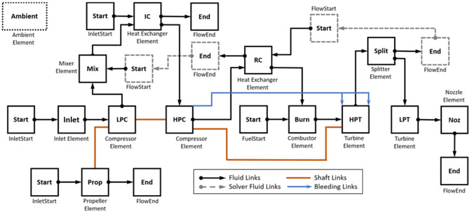
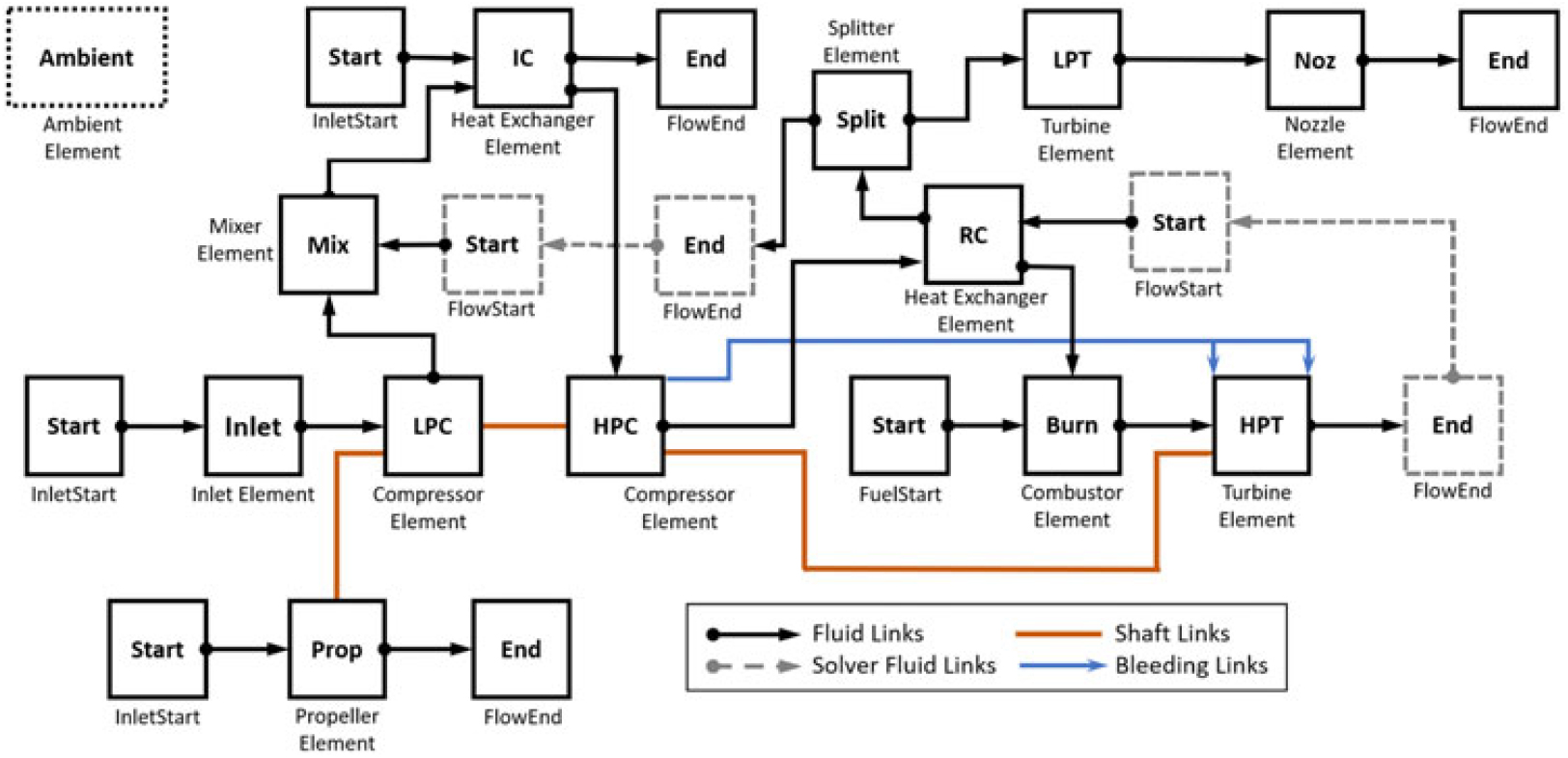
For each cycle arrangement, a single shaft configuration has been chosen to reduce the engine complexity and contain the overall weight. Moreover, the turbomachinery block has been modelled using a double compressor and turbine arrangement, as shown in Figs 1 and 2.
Standard NPSS elements have been used to create the engine models, with the exception of intake, intercooler, recuperator and combustor, which have been modified to include simple off-design performance models, as explained later on. The turbomachinery off-design behaviour has been modelled through the conventional map scaling approach implemented within the program, while the design performance is established by the external component performance models subsequently discussed.
Figures 3 and 4 provide the complete cycle schematic as realised in NPSS for the ERAST and the HPRTE semi-closed cycles, respectively. Standard NPSS ‘Fluid Links’ have been employed to model the fluid connections between components, transferring fluid proprieties such as mass flow, pressures, temperatures, etc., from each engine element to the following one. ‘Start’ and ‘End’ elements are used to initialise and terminate a flow stream, while the remaining blocks represent the main engine components used in the model. In this way, the fluid dynamics within the engine are properly modelled. Furthermore, mechanical connections between rotating elements are defined by means of ‘Shaft Links’.
ERAST Coleman engine schematic as realised in NPSS.

HPRTE engine schematic as realised in NPSS.

Since the engine model is initialised from inlet to outlet, the flow characteristics at the entrance of each component must be available to proceed with the cycle calculations(Reference Tacconi10, Reference Tacconi, Visser, MacNeill and Verstraete11). For elements like the recuperator and the mixer, this is not possible as one of the inlet flow stream proprieties depends on the performance of downstream cycle elements. Therefore, starting from an initial guess, several iterations are necessary to ensure that the flow properties at the inlet of these components are consistent with the output data of the preceding component(Reference Tacconi10). This consistency is ensured by introducing ‘Solver Fluid Links’ and combining them with appropriate fluid ‘Start’ and ‘End’ elements, linked together throughout the NPSS solver, as shown in Figs 3 and 4. The NPSS solver uses these ‘Solver Fluid Links’ in internal iterations to ensure consistency of the thermodynamic and flow characteristics between the various components. As will be shown in the results sections, this required additional iteration can hinder convergence leading to a more sparsely populated Pareto front.
In addition, a simple bleed/cooling model has been constructed using the NPSS bleed flow links to establish the amount of coolant that is required for a high pressure turbine (HPT) temperature exceeding 1,250K, as explained in Refs (Reference Tacconi10, Reference Tacconi, Visser, MacNeill and Verstraete11). According to Ref. (Reference Kumar and DeAnna12), turbine cooling should be employed above this value to avoid a considerable reduction in the component life. Consequently, the input HPT efficiency has been reduced to account for cooling losses(Reference Horlock, Watson and Jones13), as discussed in Refs (Reference Tacconi10,Reference Tacconi, Visser, MacNeill and Verstraete11).
From a thermodynamic modelling perspective, dissimilarities between the ERAST and the HPRTE engines are solely related to the different location of the splitter element (Figs 3 and 4), which affects the amount of mass flow rate entering the recuperator hot side. As a result, the total heat transfer across the heat exchanger significantly differs between the two semi-closed cycles. In particular, a much greater recuperator heat flux is achievable with the HPRTE configuration, although the HEX weight impact is expected to be more severe than for the ERAST engine.
2.2 Component performance model
A detailed performance model has been created to characterise the design and off-design behaviour of the primary gas turbine components as function of main thermodynamic variables and given flow conditions. This allows to better capture variations in component efficiencies, dimensions and feasibility as function of overall cycle variables, such as overall pressure ratio, engine mass flow, turbine inlet temperature, etc. Hence, making the performed analysis more reliable and accurate.
The model has subsequently been integrated with the NPSS calculations to have an accurate engine performance prediction within a feasible region. Moreover, a certain level of detail has been necessary in the component modelling techniques to gain sufficient geometrical information for the engine weight estimation.
2.2.1 Design performance modelling
A detailed model has been created for compressors, turbines and combustion chamber with the objective of characterising geometry, feasibility and attainable performance. For this analysis, radial turbomachinery has been employed from considerations on specific speed, specific diameter, pressure ratio and power involved. Preliminary geometrical data have been obtained using the meanline technique presented by Whitfield and Baines(Reference Whitfield and Baines14) for the estimation of component efficiencies and weights.
Centrifugal compressor
The centrifugal compressor design efficiency has been calculated considering the individual contribution of impeller, vaneless diffuser (VLD) and vaned diffuser (VD) losses. A geometrical model built for impeller and diffuser, following Refs (Reference Whitfield and Baines14,Reference Whitfield15) and (Reference Galvas16,Reference Kim, Engeda, Aungier and Amineni17) respectively, has been coupled with an empirical loss model to estimate the resultant compressor design efficiency(Reference Tacconi10, Reference Tacconi, Visser, MacNeill and Verstraete11).
Galvas(Reference Galvas16, Reference Galvas18), Oh et al.(Reference Oh, Yoon and Chung19) and Aungier(Reference Aungier20, Reference Aungier21) have proposed a set of equations to account for individual impeller loss contributions and diffuser losses. Here, the Galvas loss model has been selected due to the advantages discussed in Ref. (Reference Harley, Spence, Early, Filsinger and Dietrich22): better efficiency predictions around the compressor design point, reduced number of equations and geometrical data necessary to estimate the compressor efficiency. The shock loss relation given in Refs (Reference Aungier20, Reference Aungier21) has been added to improve the Galvas loss model prediction at high rotational speed. The resultant performance model has been shown to result in acceptable efficiency predictions for preliminary design calculations(Reference Tacconi10, Reference Tacconi, Visser, MacNeill and Verstraete11).
Aerodynamic feasibility of the resultant compressor design has additionally been ensured by setting limitations on the maximum admissible diffusion ratio (Equation (1)) and vane loading (Equation (2)),(Reference Kim, Engeda, Aungier and Amineni17, Reference Rodgers23), as explained in Refs (Reference Tacconi10, Reference Tacconi, Visser, MacNeill and Verstraete11).
 \begin{equation}
DR=\frac{W_{1s}}{W_{2}}=\frac{r_{1s}/r_{2}}{(1-2\lambda+\lambda^2/\sin^2{\alpha_{2})^{1/2}\sin{\beta_{1s}}}}\leq2.0
\label{eqn1}
\end{equation}
and
 \begin{equation}
V_{L}=\frac{2\pi(r_{3}C_{\theta3}-r_{4}C_{\theta4})}{Z_{VD}L_{v}(C_{3}-C_{4})}\leq\frac{1}{3}
\label{eqn2}
\end{equation}
The addition of these aerodynamic feasibility constraints is critical to avoid the optimiser driving designs to infeasible design regions.
Radial turbine
Radial turbine losses have been defined considering stator and rotor contributions. Preliminary geometrical data have been calculated following the design procedure presented in Refs (Reference Whitfield and Baines14, Reference Whitfield24). Two main loss models have been implemented, as proposed by Rohlik(Reference Rohlik25, Reference Glassman26) and Glassman(Reference Glassman27, Reference Wasserbauer and Glassman28). The modified version of Glassman’s equations for passage and clearance losses, presented by Baines(Reference Baines29), have been added to the model.
The Glassman loss model has been used in this analysis, as it led to a smaller error in the turbine design efficiency prediction with respect to reference data compared to the other models(Reference Tacconi10, Reference Tacconi, Visser, MacNeill and Verstraete11). The compressor and turbine total-to-total efficiencies, calculated following the described methodology, have been used in NPSS to accurately model the cycle thermodynamic behaviour.
Combustor
The combustor geometrical characterisation has been made following the consolidated preliminary design methodology discussed in Ref. (Reference Melconian and Modak30) and assuming a design burner efficiency. A model to calculate the liner wall temperature and establish cooling requirements has been implemented to identify possible unfeasible combustor designs and properly constrain the optimisation search path(Reference Tacconi10,Reference Tacconi, Visser, MacNeill and Verstraete11) .
2.2.2 Off-design performance modelling
Simple off-design performance models have been built in NPSS for the intake, heat exchangers and combustor. In particular, intake performance has been modelled using typical component maps, which relate the pressure recovery factor to the flight Mach number(Reference Kowaiski and Atkins31,Reference Schutte32) . The set of performance equations developed by Walsh and Fletcher(Reference Walsh and Fletcher33) has been used to characterise the variation of HEXs pressure losses and effectiveness in off-design. Variations in combustor efficiency and pressure losses have been modelled following Ref. (Reference Zafer34). As mentioned, the turbomachinery off-design analysis has been performed by scaling given performance maps, taken from Refs (Reference Yoshinaka, Thompson and Letourneau35,Reference Pullen, Baines and Hill36) for compressors and turbines, respectively. More details on the off-design performance model can be found in Refs (Reference Tacconi10,Reference Tacconi, Visser, MacNeill and Verstraete11).
2.3 Weight model
A component-based weight model has been linked to the performance/geometrical models to establish the weight of primary gas turbine elements, such as turbomachinery, heat exchangers, combustor, shaft, gearbox and accessories. Refs (Reference Onat and Klees37,Reference Hale38) present a detailed weight model, which has been employed for the weight estimation of these components, with the exception of HEXs and gearbox.
A detailed geometrical characterisation has not been made for the intercooler and recuperator. Instead, a weight model has been derived from proportionality relations, similar to Equation (3)(Reference McDonald2), which correlates the volume of the HEX to primary component design parameters and thermodynamic cycle data(Reference Rodgers39, Reference Head and Visser40).
 \begin{equation}
V\quad\propto\underbrace{\frac{\dot{m}_{h}}{\sqrt{{\Pi}_{{C}}}}}_{\text{Power parameter}}\times\underbrace{\left(\frac{\varepsilon}{1-\varepsilon}\frac{1}{\sqrt{\Delta P/P}}\right)}_{\text{Recuperator parameters}}\times\underbrace{\left(\sqrt{\frac{f}{j^3}}\frac{1}{\beta}\right)}_{\text{Surface geometry}}
\label{eqn3}
\end{equation}
As the HEX weight is related to the volume through the density of the employed materials, weight relations have been derived by scaling from reference component data(Reference Tacconi10,Reference Tacconi, Visser, MacNeill and Verstraete11) . In particular, Equation (4) has been employed to estimate the recuperator contribution, assuming that resultant weight is only function of cycle performance characteristics, as suggested in Refs (Reference Rodgers39–Reference Rodgers41).
 \begin{equation}
W_{RC}=W_{\rm ref}\cdot\left\{\left[\frac{\dot{m}_{h}}{\sqrt{{\Pi}_{{C}}}}\left(\frac{\varepsilon}{1-\varepsilon}\frac{1}{\sqrt{\Delta P/P}}\right)\right]/\left[\frac{\dot{m}_{h,{\rm ref}}}{\sqrt{{\Pi}_{{C},{\rm ref}}}}\left(\frac{\varepsilon_{\rm ref}}{1-\varepsilon_{\rm ref}}\frac{1}{\sqrt{(\Delta P/P)_{\rm ref}}}\right)\right]\right\}
\label{eqn4}
\end{equation}
Similarly, Equation (5) has been derived for the intercooler. Here, as suggested in Refs (Reference Rodgers41,Reference Rodgers42), the overall cycle pressure ratio dependency has been replaced by the arithmetic mean between the inlet hot and cold side pressures.
 \begin{equation}
W_{IC}=W_{\rm ref}\cdot\left\{\left[\frac{\dot{m}_{h}}{\sqrt{P_{mean}}}\left(\frac{\varepsilon}{1-\varepsilon}\frac{1}{\sqrt{\Delta P/P}}\right)\right]/\left[\frac{\dot{m}_{h,ref}}{\sqrt{P_{mean,ref}}}\left(\frac{\varepsilon_{\rm ref}}{1-\varepsilon_{\rm ref}}\frac{1}{\sqrt{(\Delta P/P)_{\rm ref}}}\right)\right]\right\}
\label{eqn5}
\end{equation}
Gearbox weight has been estimated applying the technique developed in Ref. (Reference Rejman and Rejman43). A planetary gearbox has been assumed since this configuration leads to a significant weight reduction for a given power capacity and it is commonly employed in turboprop and turboshaft engines(Reference Dudley44).
The total engine weight can be calculated by means of Equation (6) as sum of the individual component weight contributions. The complete set of equations and the reference data used for the weight model can be found in Refs (Reference Tacconi10,Reference Tacconi, Visser, MacNeill and Verstraete11).
 \begin{equation}
W_{\rm eng}=W_{{C}}+W_{{IC}}+W_{{RC}}+W_{{B}}+W_{{T}}+W_{\rm sh}+W_{\rm gear}+W_{\rm acc}
\label{eqn6}
\end{equation}
3.0 ENGINE OPTIMISATION
Each engine model has been optimised for minimum specific fuel consumption and minimum weight using the MATLAB in-built multi-objective evolutionary algorithm(Reference Messac45,Reference Deb46) . The optimisation problem has been mathematically formulated according to Equation (7), with no non-linear constraints directly applied to the optimiser, as the feasibility of the optimised solutions is ensured by the previously discussed models(Reference Tacconi10,Reference Tacconi, Visser, MacNeill and Verstraete11) .
 \begin{equation} {\rm min}[\bar{J}(x)]={\rm min} \left[\begin{array}{c} J_{1}(x) \\ J_{2}(x) \end{array}\right] ={\rm min} \left[\begin{array}{c} SFC_{\rm av}(x) \\ W_{\rm eng}(x) \end{array}\right] \label{eqn7} \end{equation}
subjected to
 \[x_{l}\leq x\leq x_{u}\]
The minimum specific fuel consumption objective  $SFC_{\rm av}$ has been defined by averaging the engine design and part-power SFC, given at 75%, 50% and 25% of the engine design power output (Equation (8)).
 $$SF{C_{{\rm{av}}}} = {{SF{C_{des}} + SF{C_{75\% }} + SF{C_{50\% }} + SF{C_{25\% }}} \over 4}$$
The MATLAB algorithm named ‘gamultiobj’ has been linked to NPSS and the component performance/weight model as shown in Fig. 5. The optimiser creates a new design vector, selected between the lower and upper bounds, which is required to run the thermodynamic cycle model in NPSS, whose turbomachinery design efficiencies are initially guessed.
Optimisation modelling diagram.

Once NPSS has converged, the component inlet and outlet flow data have been defined, and they can be used by the component performance/weight model to establish size, performance and feasibility of the major engine elements considered. This process iteratively updates the turbomachinery efficiency, leading to an accurate estimation of the attainable cycle design performance. Once the design point has been fully characterised, the off-design part-power analysis is performed in NPSS. Any unfeasible or unconverged solution is returned to the optimisation algorithm with the worst rank possible, such that it will be discarded in the next generation(Reference Tacconi10,Reference Tacconi, Visser, MacNeill and Verstraete11) .
Table 1 summarises the thermodynamic design variables used for the optimisation of the semi-closed cycle. The optimiser can vary the values of these variables between the lower ( $x_{l}$) and upper bounds (
 $x_{u}$), indicated in Table 1, to find the optimum trade-off between engine weight and average SFC. Similar tables are presented in Refs (Reference Tacconi10,Reference Tacconi, Visser, MacNeill and Verstraete11) for the simple recuperated and the intercooled-recuperated open cycle solutions. In addition to these variables, some compressor and turbine geometrical parameters are directly controlled by the optimiser to ensure that the optimal turbomachinery efficiency is obtained for the given flow conditions(Reference Tacconi10, Reference Tacconi, Visser, MacNeill and Verstraete11).
Coleman/HPRTE optimisation design variables and relative bounds

The design vector lower and upper bounds have been set according to the common practices reported in the references shown in Table 1 and after a preliminary sensitivity study performed with NPSS. The initial population size has been set following the rule of thumb of using an initial population of at least ten times the number of the design variables(Reference Storn50). This ensures a smooth Pareto frontier.
4.0 RESULTS
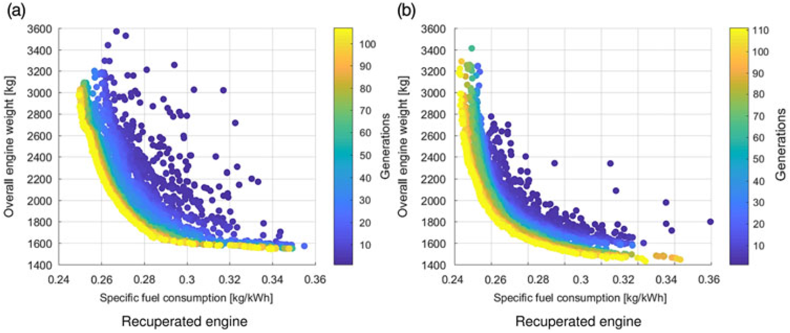
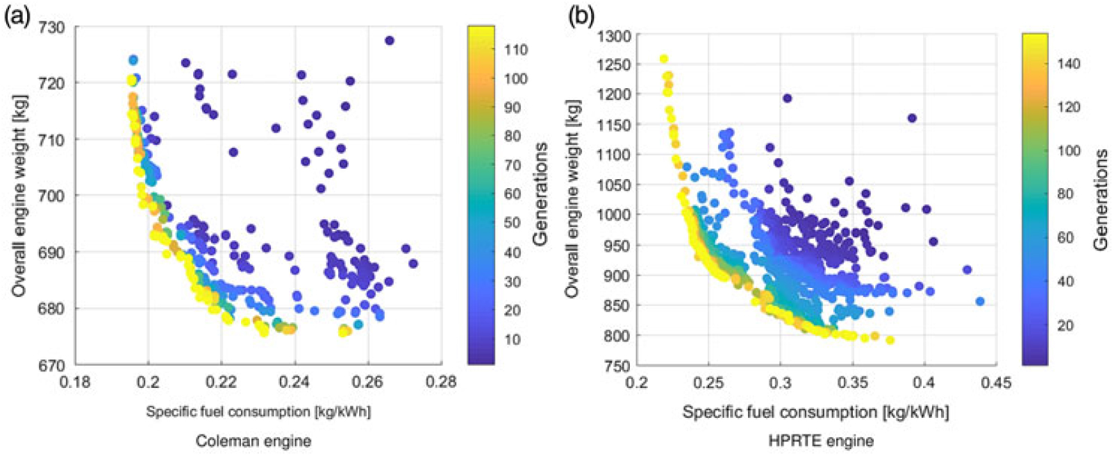
Results have been obtained for the four engine cycles analysed, using the ERAST case study(Reference Bettner, Blandford and Rezy9) as reference for main design data. In particular, each engine model has been optimised for minimum SFC and engine weight at a flight altitude of 90,000 ft, a flight Mach number of 0.4 and an engine design power output of 300 hp (∼223.71 kW). Figures 6 and 7 illustrate the optimisation results and the Pareto frontier, given by the last generation of each optimisation (shown in yellow) for the open and the semi-closed cycles considered within this work. Note the different scales used on each of the Figs 6 and 7.
Open cycles Pareto optimal solutions.

Semi-closed cycles Pareto optimal solutions.

As indicated previously, the optimisation of the semi-closed cycle arrangements is complicated by numerical convergence issues due to the extra constraints and fluid solver links required in the analysis. This is evidenced by the less dense point cloud and non-full Pareto frontier and the higher number of generations needed to obtain convergence of the semi-closed cycles (Fig. 7). Nonetheless, convergence is sufficient to identify trends and compare the semi-closed and open cycle engines.
4.1 General considerations
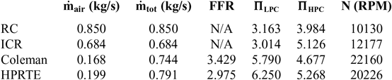
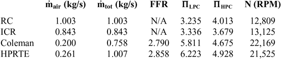
Both the Coleman and the HPRTE configurations show a far more significant degree of compactness compared to the open cycles for the same  $SFC_{av}$, leading to a weight less than half that of the open cycle engines. This can mostly be attributed to the considerably smaller inlet mass flow required for a given engine power output due to the recirculation of gases in the cycle. Part of the compactness benefit also comes from the significantly higher overall cycle pressure ratio achievable with a semi-closed cycle configuration, leading to a significant reduction of the low pressure components and the recuperator weight (Tables 2 and 3). A higher overall pressure ratio is possible due to the significantly lower engine inlet mass flow necessary, about three times less than for the ICR configuration. This allows for a significantly higher low pressure compressor (LPC) pressure ratio with a greatly reduced compressor power demand. For the open cycles a much larger LPC is required due to the higher mass flow rate. This larger LPC is limited in pressure rise by the maximum admissible diffusion ratio (see Equation (1)). As a consequence, semi-closed cycles display a slight improvement in the minimum
 $SFC_{av}$ achievable with respect to the conventional solutions.
Important design cycle parameters (min  $SFC_{av}$)

Important cycle parameters (min  $W_{eng}$)

Differences between the Coleman and the HPRTE cycle results (Fig. 7) come from the different position of the splitter element (Figs 1 and 2). In the HPRTE configuration the whole engine mass flow gets cooled down in the recuperator before entering the low pressure turbine (LPT). Thus less power can be extracted from the LPT, which leads to a higher HPT loading. This results in a stronger impact of the turbomachinery and recuperator on the overall engine weight, as a greater mass flow is needed to ensure the required power output. In the Coleman engine, only part of the mass flow gets cooled down in the recuperator which explains the differences in engine weights in Fig. 7.
Furthermore, because the LPC and HPT pressure ratios are constrained by the mixer, the recuperator effectiveness has to be adjusted to ensure a sufficiently high HEX hot-side exit temperature for the enthalpy jump across the LPT. As a consequence, a slightly higher inlet mass flow is observed in the HPRTE configuration, with a comparatively lower feedback flow rate (FFR), defined as the ratio between the inlet fresh air to the recirculated gases. Since only the fresh air is reacting with the fuel, a slightly higher  $SFC_{\rm av}$ is observed in the HPRTE model, explaining the differences in the SFC behaviour between the Coleman and the HPRTE engines.
Tables 2 and 3 display main design cycle data associated with the minimum SFC and weight solutions for the four engine architectures analysed within this work. As visible, because of the recirculated flow, semi-closed cycles require a much smaller inlet fresh air than conventional gas turbines for a given engine power output. This considerable boost in specific power allows to strongly reduce the turbomachinery weight contribution. Furthermore, the higher OPR achieved by the Coleman and the HPRTE engines, not only improves the cycle fuel efficiency, but also helps to contain the intercooler and recuperator sizes, thus improving the overall engine compactness.
4.2 Part-power behaviour
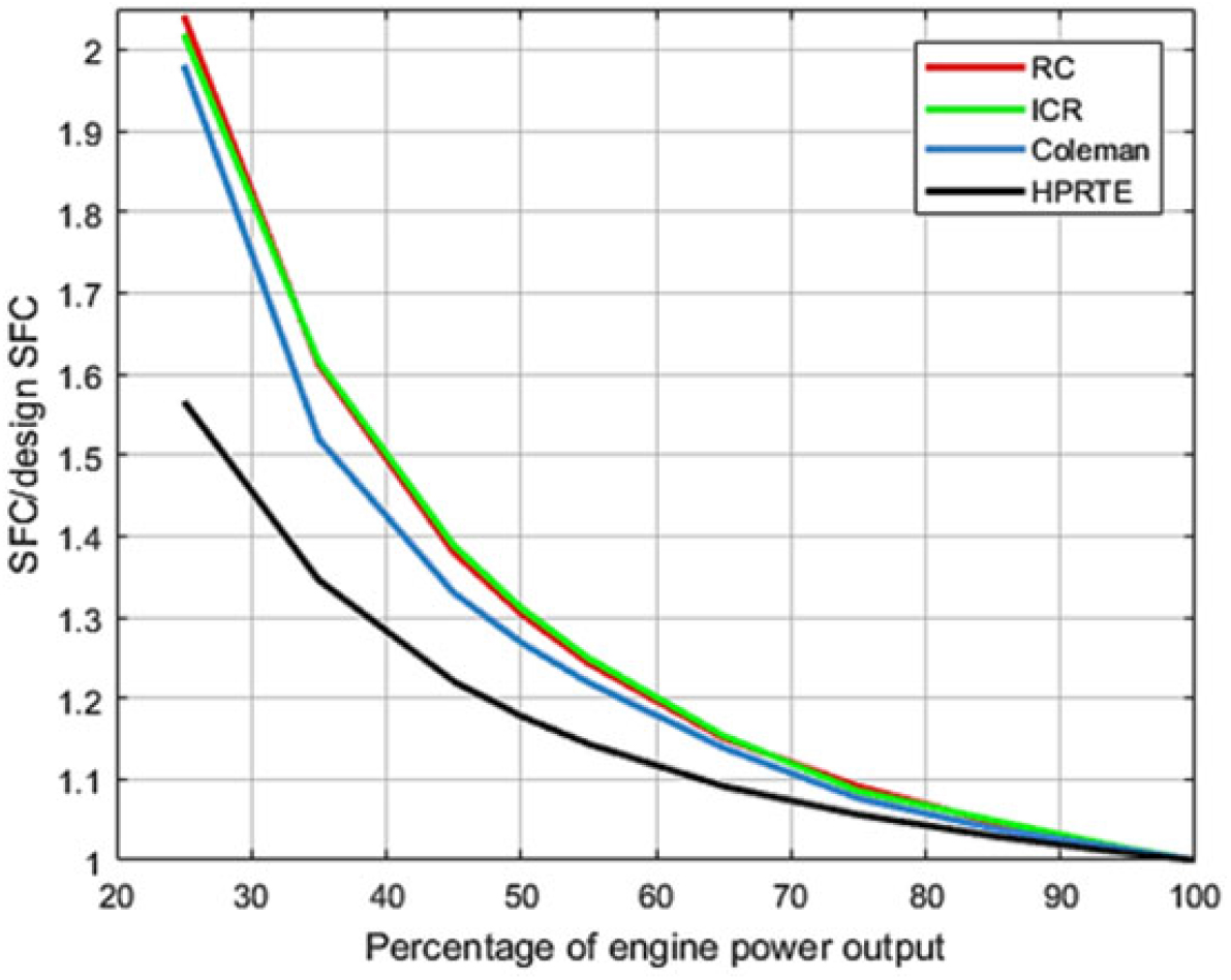
Ref. (Reference Meitner, Laganelli, Senick and Lear7) has shown that the HPRTE arrangement presents a much flatter SFC curve at part-power off-design operating points with respect to conventional configuration. This aspect has been confirmed by this analysis as well. In particular, Fig. 8 has been generated by selecting a common  $SFC_{av}$ between the four engines considered (∼0.253 kg/kWh) and normalising the part-power SFC points with respect to the design value.
Engine part-power performance comparison.

As visible, the HPRTE model exhibits superior performance at low engine power demands with respect to all the remaining engine models. The differences with the Coleman engine are associated once again with the splitter location. As the engine power output is reduced, the heat transfer across the recuperator is far more significant in the HPRTE configuration than in Coleman cycle. The recirculation ratio of the first can be better adjusted to keep the high pressure components close to their peak efficiency, as also shown in Ref. (Reference Meitner, Laganelli, Senick and Lear7). This is only partially achievable with the Coleman cycle arrangement as less feedback flow rate is available and sufficient power has to be extracted from the LPT.
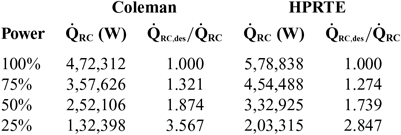
Table 4 shows the recuperator heat flux variation as a function of the engine power output for the Coleman and the HPRTE engines. These data have been obtained from NPSS for the Coleman and the HPRTE arrangement at the previously analysed SFC point, with almost equivalent engine design specs. As visible, the HPRTE configuration allows for a greater heat flux across the recuperator in design (100% power), despite the more significant HEX hot-side exit temperature constraints set by the LPT.
Recuperator part-power heat flux variation

In off-design, the recirculation ratio is varied to ensure a highly effective heat flux across the recuperator. However, as shown by the recuperator design to off-design heat flux ratio ( $\dot{Q}_{{RC,{\rm des}}}/\dot{Q}_{{RC}}$), the HPRTE configuration allows for a better control of the FFR, leading to a much higher heat transfer across the recuperator even at low engine power output, which is the main reason associated with the flatter SFC curve displayed in Fig. 8.
4.3 Semi-closed cycle results
The optimisation results for the Coleman and the HPRTE semi-closed cycle configurations are reported below, discussing the influence of major thermodynamic design variables (Table 1) on the average SFC and weight objectives.
4.3.1 Effects of OPR and rotational speed
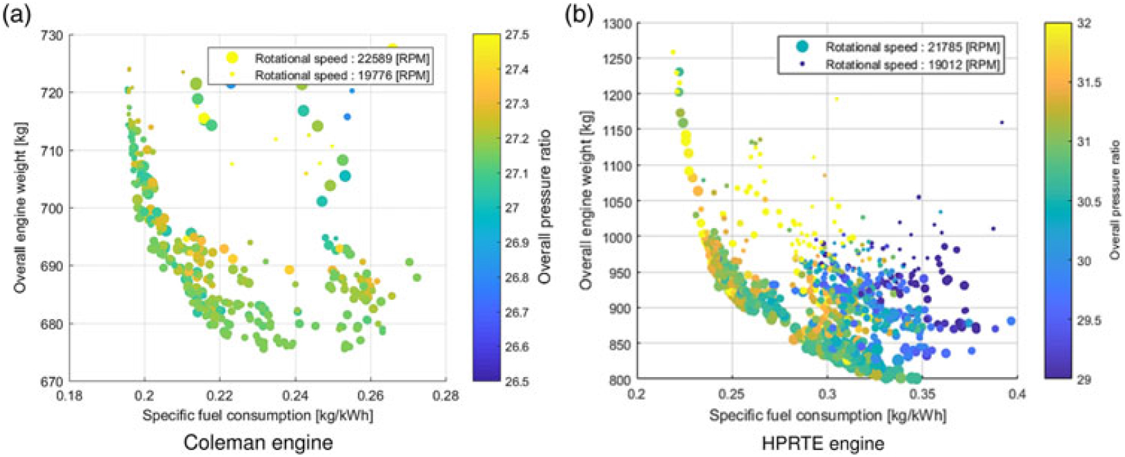
Figure 9 displays the influence of overall pressure ratio and rotational speed on the Pareto frontiers. In particular, an OPR of approximately 27.3 and 31.0 leads to the minimisation of both objectives for the Coleman and the HPRTE engines, respectively. The largest pressure rise is located on the LPC, as low power is required by this component due to the reduced inlet mass flow with respect to the open cycle cases. The simple recuperated and intercooled-recuperated cycles have OPRs of approximately 13 and 16, respectively.
Effect of pressure ratio and rotational speed.

Minimum weight solutions are obtained at higher rotational speeds as high rotational speeds reduce the size of the turbomachinery block, while approximately the same pressure ratio is achieved through larger rotating components for minimum SFC. In fact, as the dimensions of the turbomachinery reduce, losses due to the Reynolds effects and secondary flows become more significant, decreasing the efficiency of compressors and turbines.
4.3.2 Effects of Turbine Inlet Temperature (TIT) and equivalence ratio
As for the open cycle, increasing the TIT leads to an improvement in both cycle thermal efficiency and specific power. The maximum achievable turbine inlet temperature is limited by turbine, combustor and recuperator materials. Since the first two aspects are considered within the component model and the selection of the optimisation bounds, a condition on the recuperator inlet temperature (RIT) has to be defined to deal with unfeasible HEX hot-side temperatures.
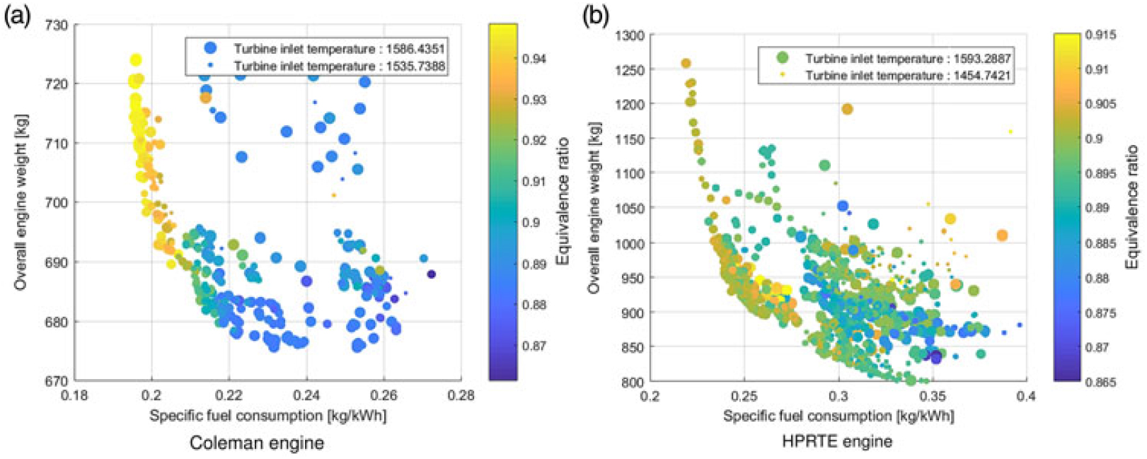
In particular, a maximum RIT value of  $900^\circ{\rm{C}}$ (1173.15K) has been defined for design and off-design calculations, which represents the maximum limit for metal based alloys(Reference McDonald3). Therefore, the optimiser maximises the TIT, respecting this limitation on the RIT. A TIT value of approximately 1,560K and 1,565K has been selected by the optimiser for the ERAST and the HPRTE engine, respectively (Fig. 10).
Effect of turbine inlet temperature and equivalence ratio.

The equivalence ratio variable, given as the ratio between the actual and the stoichiometric fuel to air ratio, has been used in design to directly control the FFR, as done in the ERAST analysis(Reference Bettner, Blandford and Rezy9). In particular, a higher equivalence ratio corresponds to a larger recirculation ratio, leading to lower inlet fresh air requirements and vice versa. Figure 10 shows the effects of the equivalence ratio on the considered semi-closed cycles.
Minimum average SFC solutions are achieved for a  $\phi$ value close to the optimisation upper bound, approximately 0.95 and 0.91 for the Coleman and the HPRTE engines. The differences between these cycle configurations are associated to the dissimilar splitter location previously explained. In fact, as the HPRTE engine requires more fresh air,
 $\phi$ has to be adjusted to supply sufficient mass flow to ensure the combustion.
On the other hand, minimum weight solutions are obtained for a lower equivalence ratio of about 0.88 for both engine models since a high feedback flow ratio has an important impact on the high pressure component weights, as it directly influences the total mass flow amount of the recirculated loop.
4.3.3 Effects of HEX variables
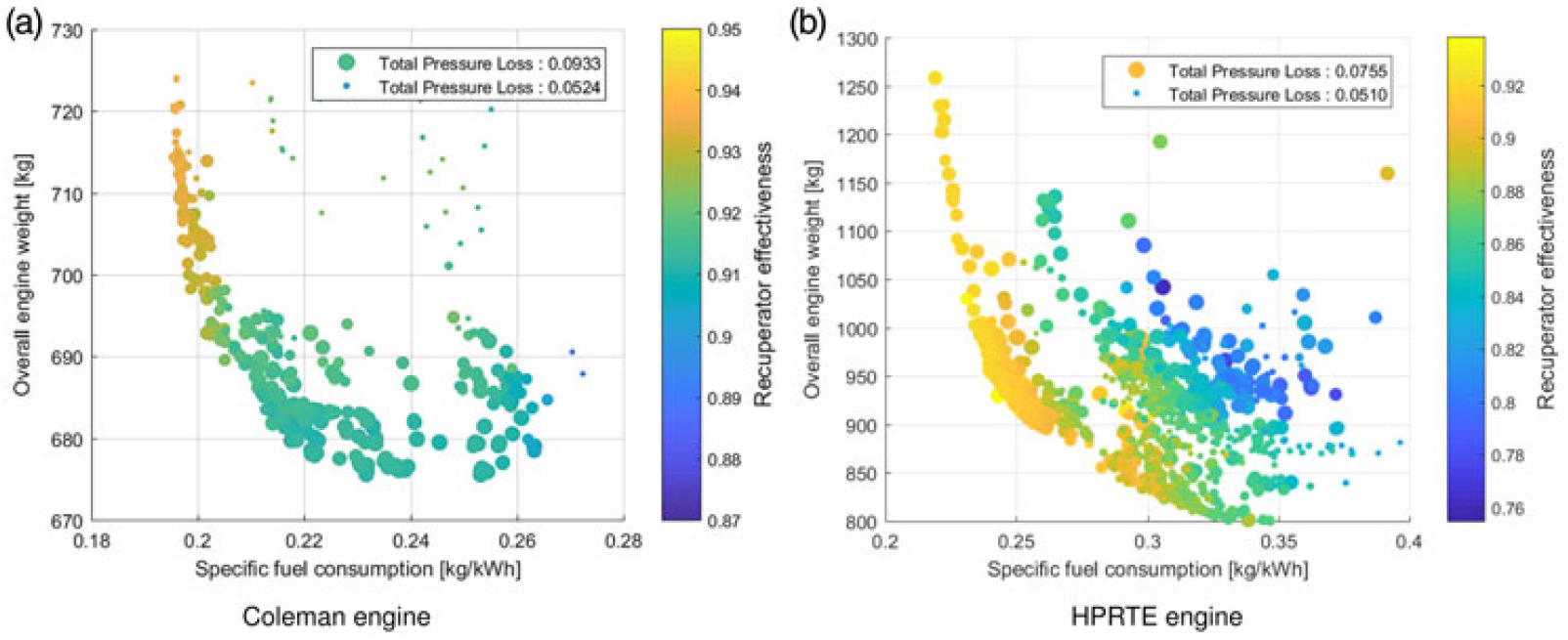
Figure 11 shows the impact of recuperator effectiveness and total pressure losses, defined as the sum of hot and cold side pressure drops on the Pareto frontiers. As can be expected, high effectiveness and reduced pressure losses result in minimal SFC solutions. Logically the opposite trend is visible in minimum weight solutions. Figure 11 highlights the importance of the recuperator for semi-closed cycle arrangements, as a relatively high value of  $\varepsilon$ is maintained across the entire Pareto frontier in both the Coleman and the HPRTE configurations.
Effect of recuperator effectiveness and total pressure losses.

The need for a high recuperator effectiveness is a result of the high pressure recirculated loop arrangement. As the OPR remains high in minimum weight solutions, the recuperator volume still stays contained (see Equation (3)). As the recuperator effectiveness goes down, a greater total engine mass flow is required to maintain the required power output. Hence, the optimiser reduces the recuperator weight contribution, by reducing  $\varepsilon$ and increasing
 $\Delta P/P$, until the turbomachinery impact starts to become more significant.
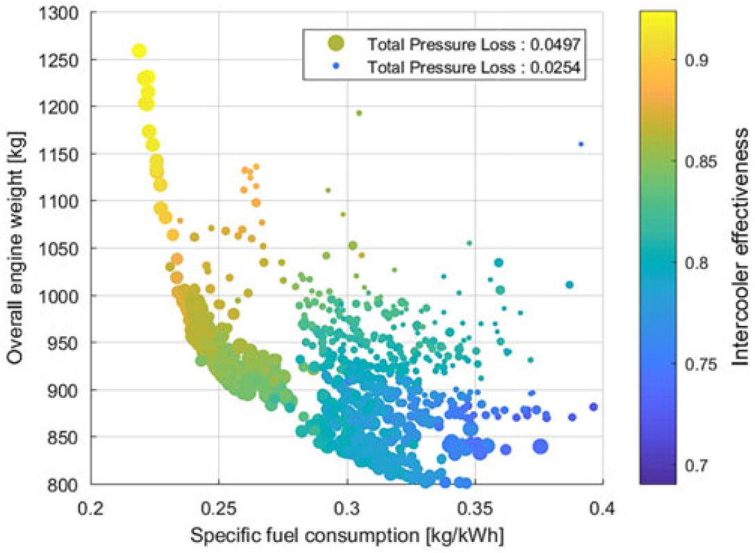
The intercooler parameters have different effects on the Pareto optimality of the Coleman and the HPRTE arrangements. In particular, it has been observed that the intercooler plays a far less important role than the recuperator in the Coleman engine configuration. Consequently, the optimiser sets the effectiveness of this component to approximately 0.7 for both objectives.
For a fixed engine power output and TIT, an improvement in  $\varepsilon_{IC}$ causes a reduction in the HPC power demand, which increases the HPT exit temperature. As the maximum RIT is limited by the recuperator material, this limits the allowed HPT exit temperature. Since in semi-closed cycles the HPT exit pressure is additionally fixed by the mixer, the power split between HPT and LPT is consequently constrained.
Because a lower mass flow rate passes through the recuperator hot side in the ERAST Coleman engine, a high effectiveness has to be kept in this component to maximise the heat transfer and improve the SFC, while the intercooler effectiveness has to be limited to ensure a feasible RIT. In addition, as the recuperator effectiveness does not impact the LPT inlet temperature, no strong limitation on the recuperator hot side exit temperature is present. This enables a small temperature difference between the two inlet stream of the mixer, diminishing the HPC power demand even for a lower  $\varepsilon_{IC}$ value.
In the HPRTE cycle, on the other hand, the recuperator exit temperature has to be sufficiently high to allow for a sufficient LPT power extraction. As a consequence, the temperature difference at the mixer inlet is far greater than the Coleman case. Therefore, the intercooler effectiveness plays a more important role in reducing the HPC inlet temperature, as shown in Fig. 12. For the Coleman engine, the intercooler effectiveness is approximately 0.7 across the entire Pareto frontier.
Effect of intercooler parameters on the HPRTE Pareto optimality.

4.3.4 Effects of turbomachinery efficiency
As previously discussed, the shaft rotational speed significantly affects peak efficiencies and relative sizes of the turbomachinery. As high compressor and turbine efficiencies are required to minimise both SFC and engine weight, by reducing the work load of these components, the optimiser tries to maximise the turbomachinery performance for every given inlet flow condition, as shown in(Reference Tacconi10).
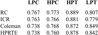
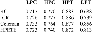
Tables 5 and 6 show the turbomachinery design performance for the minimum average SFC and weight conditions labelled in Tables 2 and 3. The effects of the higher specific power in the two semi-closed cycles are particularly visible in the lower LPC efficiency of minimum SFC solutions, which is between 2 and 3 points lower than for the equivalent open cycles, while comparable values are achieved for minimum weight solutions.
Design turbomachinery efficiency (min  $SFC_{av}$)

Design turbomachinery efficiency (min  $W_{eng}$)

An almost equivalent performance is obtained across the high pressure components of semi-closed and open cycles as those components see the whole engine flow. However, comparatively poor performance has been obtained across the open cycles LPT, as a consequence of the low workload on this component, which is translated in high exit velocity losses. Thus, indicating that a different engine architecture (with single or axial turbines) could be more optimal for open cycles than the selected one.
5.0 CONCLUSIONS
A preliminary study has been performed to identify the potential of semi-closed cycles for high-altitude UAV propulsion. A multi-objective optimisation tool has been created to support the preliminary cycle analysis, developing a sufficiently detailed performance and weight model to determine attainable performance, dimensions and feasibility of main gas turbine components as function of the cycle thermodynamics during the optimisation. Pareto frontiers of two semi-closed cycles and two equivalent open cycles, obtained for minimum SFC and weight as target, have been compared.
Several conclusions can be derived from this work on the possible implementation and application of semi-closed cycles to UAV applications:
A significant engine compactness can be achieved using semi-closed cycle configurations, leading to an engine weight that is less than half that of conventional open cycles for the same power output and SFC item. Both semi-closed cycles operate at higher overall pressure ratios than their open cycle counterparts. This results in improved cycle efficiencies and smaller engine mass.
This higher OPR and smaller mass flow requirement enable the use of high effectiveness recuperators whose mass penalty would otherwise be prohibitive.
Better overall cycle performance can be expected in semi-closed cycles. In particular, the Coleman engine is shown to be less affected by the employed feasibility constraints, leading to a slightly better average
$SFC_{\rm av}$ values than the HPRTE model.Far superior off-design SFC has been observed for the HPRTE engine at reduced engine power demands, making this configuration interesting for applications that see the engine operating at low part-power demands.
On the contrary, the Coleman engine model exhibits greater performance in design mode than the HPRTE, while at low engine power output, no remarkable differences can be expected with respect to a conventional ICR engine.