1. Introduction
Orogenic belts typically include a range of contractional, strike-slip and extensional shear zones and faults that evolve during plate convergence (e.g. Dewey et al. Reference Dewey, Hempton, Kidd, Saroglu, Şengör, Coward and Ries1986). Tectonic models for the mid-crustal parts of orogens are highly dependent upon the dating of deformation events that can be linked kinematically to displacements along regional-scale shear zones and faults. The structural analysis of igneous intrusions that were emplaced at a known time relative to a particular set of regionally developed fabrics and/or shear zones has proved particularly effective in constraining the timing of tectonic events in various orogens worldwide (e.g. Paterson & Tobisch, Reference Paterson and Tobisch1988; Ingram & Hutton, Reference Ingram and Hutton1994; Jacques & Reavy, Reference Jacques and Reavy1994; De Saint Blanquat & Tikoff, Reference De Saint Blanquat, Tikoff, Bouchez, Hutton and Stephens1997; Schofield & D'Lemos, Reference Schofield and D'Lemos1998; Strachan, Martin & Friderichsen, Reference Strachan, Martin and Friderichsen2001; Grocott & Taylor, Reference Grocott and Taylor2002; Rosenberg, Reference Rosenberg2004).
Integrated structural and geochronological studies of syn-kinematic igneous complexes are increasing steadily the number of reliable constraints on the timing of events within the Early Palaeozoic Caledonian orogen in Scotland (Fig. 1). The Caledonian orogeny resulted from the closure of the Iapetus Ocean: an Ordovician arc–continent collision known as the Grampian event (Lambert & McKerrow, Reference Lambert and McKerrow1976; Soper, Ryan & Dewey, Reference Soper, Ryan and Dewey1999; Oliver et al. Reference Oliver, Chen, Buchwaldt and Hegner2000) was followed during the Silurian by the oblique collision of three continental blocks, Avalonia, Laurentia and Baltica (Soper & Hutton, Reference Soper and Hutton1984; Pickering, Bassett & Siveter, Reference Paterson and Tobisch1988; Soper et al. Reference Soper, Strachan, Holdsworth, Gayer and Greiling1992). Baltica collided with the segment of the Laurentian margin that incorporated northern Scotland, to result in the Scandian orogenic event (Coward, Reference Coward, Hardman and Brooks1990; Dallmeyer et al. Reference Dallmeyer, Strachan, Rogers, Watt and Friend2001; Dewey & Strachan, Reference Dewey and Strachan2003; Kinny et al. Reference Kinny, Strachan, Rogers, Friend and Kocks2003). Scandian crustal thickening was followed by displacements along orogen-parallel strike-slip faults, including the Great Glen Fault (Fig. 1). Slab break-off during the final phase of the orogeny resulted in the generation of a variety of granites and syenites (e.g. Atherton & Ghani, Reference Atherton and Ghani2002; Fowler et al. Reference Fowler, Kocks, Darbyshire and Greenwood2008; Oliver, Wilde & Wan, Reference Oliver, Wilde and Wan2008; Neilson, Kokelaar & Crowley, Reference Neilson, Kokelaar and Crowley2009). Early members of the suite were emplaced along Scandian thrusts (Kinny et al. Reference Kinny, Strachan, Rogers, Friend and Kocks2003; Kocks, Strachan & Evans, Reference Kocks, Strachan and Evans2006; Goodenough et al. Reference Goodenough, Millar, Strachan, Krabbendam and Evans2011), whereas later members appear to have been emplaced along steeply dipping strike-slip or normal faults (Hutton, Reference Hutton1988a ,Reference Hutton b ; Hutton & McErlean, Reference Hutton and McErlean1991; Rogers & Dunning, Reference Rogers and Dunning1991; Jacques & Reavy, Reference Jacques and Reavy1994; Stewart et al. Reference Stewart, Strachan, Martin and Holdsworth2001; Hughes et al. Reference Hughes, Goodenough, Walters, McCormac, Gunns and Lacinska2013).
Regional geology map of the Scottish Highlands north of the Great Glen Fault. Inset map shows the relative positions of Laurentia, Baltica, Avalonia and Gondwana following the closure of the Iapetus Ocean (Caledonide–Appalachian belt in black). Abbreviations: A – Assynt; B – Ballachulish Granite; BHT – Ben Hope Thrust; BK – Ben Klibreck; BW – Ben Wyvis; C – Cluanie Granite; CT – Clunes Tonalite; DF – Dornoch Firth; GGF – Great Glen Fault; K – Kirtomy; MT – Moine Thrust; NT – Naver Thrust; R – Rogart igneous complex; Ra – Ratagain intrusion; S – Strontian Granite; SBT – Sgurr Beag Thrust; SDT – Skinsdale Thrust; SFF – Strath Fleet Fault; SHG – Strath Halladale Granite; SN – Strathnaver Granite; ST – Swordly Thrust.

In common with most other orogens, studies of the emplacement of individual igneous complexes within the Caledonides have largely focused on one main tectonic control, which might be thrusting, strike-slip or extension. In this paper we summarize the structural setting, emplacement and U–Pb geochronology of the Rogart igneous complex, a member of the Newer Granite suite in NW Scotland (Fig. 1). This is of particular significance because, uniquely, its emplacement appears to have overlapped the switch from regional contraction to strike-slip within this sector of the Caledonides.
2. Geological setting
In northern Scotland, the Caledonian orogen is largely underlain by metasedimentary rocks of the lower Neoproterozoic Moine Supergroup (Holdsworth, Strachan & Harris, Reference Holdsworth, Strachan, Harris, Gibbons and Harris1994; Strachan et al. Reference Strachan, Holdsworth, Krabbendam, Alsop, Law, Butler, Holdsworth, Krabbendam and Strachan2010; Fig. 1). The western margin of the orogen is defined by the Moine Thrust, which is overlain by Moine rocks assigned to the Morar Group. In Sutherland, the Morar Group lies structurally beneath the Naver Thrust that carries the Loch Coire Migmatite Complex, and further east, the Skinsdale Thrust carries the unmigmatized Moine rocks of the Scaraben Succession (Fig. 1). U–Pb geochronology shows that the Loch Coire Migmatite Complex formed during the Ordovician Grampian orogenic event at ~470–460 Ma (Kinny et al. Reference Kinny, Friend, Strachan, Watt and Burns1999). This was followed by widespread Silurian (Scandian) ductile deformation and thrusting that propagated towards the foreland and culminated in development of the Moine Thrust Zone (Holdsworth, Strachan & Alsop, Reference Holdsworth, Strachan and Alsop2001; Holdsworth, Alsop & Strachan, Reference Holdsworth, Alsop, Strachan, Ries, Butler and Graham2007; Johnson & Strachan, Reference Johnson and Strachan2006; Alsop et al. Reference Alsop, Cheer, Strachan, Krabbendam, Kinny, Holdsworth, Leslie, Law, Butler, Holdsworth, Krabbendam and Strachan2010; Leslie et al. Reference Leslie, Krabbendam, Kimbell, Strachan, Law, Butler, Holdsworth, Krabbendam and Strachan2010). U–Pb dating of syn-kinematic intrusions constrains thrusting to have occurred at ~435–425 Ma (Kinny et al. Reference Kinny, Strachan, Rogers, Friend and Kocks2003; Kocks, Strachan & Evans, Reference Kocks, Strachan and Evans2006; Goodenough et al. Reference Goodenough, Millar, Strachan, Krabbendam and Evans2011). A broad arcuate swing defined by the regional foliation and ductile thrusts has been attributed to the development of a major thrust culmination, both within the Moine rocks and the underlying Moine Thrust Zone of the Assynt area (Fig. 1; Elliott & Johnson, Reference Elliott and Johnson1980; Butler & Coward, Reference Butler and Coward1984; Leslie et al. Reference Leslie, Krabbendam, Kimbell, Strachan, Law, Butler, Holdsworth, Krabbendam and Strachan2010).
The Rogart igneous complex is mainly hosted by Moine metasediments of the Morar Group (Fig. 1; Soper, Reference Soper1963; H. Kocks, unpub. Ph.D. thesis, Oxford Brookes Univ., 2002). Regionally, these are typically unmigmatized psammites with subordinate pelitic horizons; sedimentary structures such as cross-bedding are present in areas of low tectonic strain (e.g. Krabbendam, Prave & Cheer, Reference Krabbendam, Prave and Cheer2008; Bonsor et al. Reference Bonsor, Strachan, Prave and Krabbendam2012). Occasional concordant amphibolite sheets are interpreted as deformed and metamorphosed mafic intrusions. The dominant structures are tight-to-isoclinal D2 folds that carry an axial-planar mica fabric (S2) and deform an earlier bedding-parallel schistosity (S1). The main foliation is therefore a composite S0/S1/S2 fabric; it carries an ESE-plunging L2 mineral and extension lineation that is interpreted to lie parallel to the direction of tectonic transport during Caledonian (Scandian) thrusting. D2 axes commonly trend parallel to L2 as a result of intense rotation during ductile thrusting. Regional metamorphic grade during D2 was within the low- to mid-amphibolite facies (Strachan & Holdsworth, Reference Strachan and Holdsworth1988).
The D2 Naver Thrust crops out a few kilometres to the northeast of the Rogart igneous complex (Fig. 1). The Ordovician Loch Coire Migmatite Complex in the hangingwall is strongly reworked and blastomylonitic in the immediate vicinity of the Naver Thrust. At structurally higher levels, where the level of superimposed Scandian strain is less, the migmatites are dominated by regularly layered, stromatic metasedimentary gneisses. The degree of partial melting is variable and leucosomes may increase and coalesce to form bodies of schlieric diatexite that intrude and cross-cut migmatitic layering. Semi-pelitic migmatites comprise biotite + quartz + plagioclase + K-feldspar ± muscovite ± garnet. Melanosomes comprise coarse-grained brown biotite, whereas leucosomes show abundant igneous plagioclase, K-feldspar, recrystallized quartz and rare garnet. The mineral assemblage in the leucosomes is interpreted to have resulted from biotite dehydration melting at ~8–10 kbar (H. Kocks, unpub. Ph.D. thesis, Oxford Brookes Univ., 2002).
The SE part of the Rogart igneous complex is thought to be overlain unconformably by Old Red Sandstone (Devonian) sedimentary rocks, although the contact is not exposed (Fig. 2; Read et al. Reference Read, Ross, Phemister and Lee1925; Read, Phemister & Ross, Reference Read, Phemister and Ross1926). Both are limited to the south by the Strath Fleet Fault (Fig. 2), which is likely to have a complex history of movement. The fault lies along and parallel to a NW-trending lineament termed the Loch Shin Line, which is defined by a concentration of late Caledonian minor intrusions with mantle parentage (Watson, Reference Watson1984). The Strath Fleet Fault has been interpreted as an anti-Riedel shear to the late Caledonian sinistral Great Glen Fault system, and early dextral displacement inferred (Johnson & Frost, Reference Johnson and Frost1977; Watson, Reference Watson1984). This was followed by a post-Devonian component of normal displacement with downthrow to the northeast (Fig. 2).
Simplified geological map of the Rogart igneous complex, also showing areas of injection migmatites within host psammites of the Morar Group. See Figure 1 for location. Abbreviations: CN – Cnoc Arthur; CM – Creag Mhor; GB – Garvoult Bridge; MR – Marian's Rock; RS – Rogart Station; SFF – Strath Fleet Fault. Marginal numbers are UK National Grid coordinates in area ‘NC’.

3. Geology of the Rogart igneous complex and related injection phenomena
The Rogart igneous complex sensu stricto is a zoned central pluton formed of an outermost quartz monzodiorite, a granodiorite and an innermost granite (Read et al. Reference Read, Ross, Phemister and Lee1925; Read, Phemister & Ross, 1926; Soper, Reference Soper1963; H. Kocks, unpub. Ph.D. thesis, Oxford Brookes Univ. 2002). However, the term ‘Rogart igneous complex’ is used in a wider sense here to include a separate body of quartz monzodiorite, the Creag Mhor sheet, and a range of slightly older leucogranites and associated injection migmatites developed within the country rocks to the north and the east (Fig. 2). Evidence presented below suggests that the leucogranites resulted from partial melting of Moine rocks at a deeper structural level, possibly as a consequence of the injection of mafic magma associated with the main pluton. Hence these are an integral part of the magmatic record in the Rogart area.
3.a. Leucogranites and injection migmatites
The Morar Group rocks to the north and east of the central pluton are anomalous because they are typically coarse grained and gneissic, and locally contain discrete melanosomes and leucosomes, thus conforming to commonly accepted definitions of metatexite (e.g. Brown, Reference Brown1973). They also contain variable proportions of intrusive leucogranite (Fig. 2). There is every gradation from occasional centimetre–metre-scale sheets to areas of intensely sheeted ‘injection migmatites’, which in turn pass transitionally into coherent bodies of leucogranite up to 1–2 km2 in extent that contain relict schlieren and rafts of psammite and semi-pelite. Notable areas of injection migmatite and leucogranite occur near Rogart Station [NC 720 027] and at Marian's Rock [NC 748 013] (Fig. 3a, b). Leucogranite sheets are also focused in the vicinity of the Naver Thrust, both in its footwall and hangingwall. The leucogranites are fine-to-medium grained, and mainly comprise quartz + plagioclase + K-feldspar ± biotite ± muscovite. They are petrographically distinct from the leucosomes within the Loch Coire Migmatite Complex in two important respects: (1) although commonly deformed, magmatic-state fabrics are indicated by the straight grain boundaries of eu- to subhedral early crystallized phases, and (2) they lack garnet. Leucogranite sheets typically have sharp contacts with their host rocks; although some sheets are highly discordant to metasedimentary layering, most are concordant to subconcordant.
(a) Banded Morar Group psammites intruded by S2-parallel leucogranite sheets (arrowed); (b) injection migmatites within the Morar Group showing relict layers of psammite (arrowed) engulfed by S2-parallel leucogranite. Both outcrops in the vicinity of Marian's Rock [NC 748 013]. Camera lens cap for scale is 5 cm in diameter.

On the basis of dissimilar geochemistry (being relatively rich in Fe2O3, MgO, TiO2 and related trace elements at comparable SiO2) and rare earth element (REE) patterns (in particular a persistent negative Eu anomaly and relatively high heavy REEs), the leucogranites are regarded as petrogenetically distinct from the high Ba–Sr magmas of the central pluton (Fowler et al. Reference Fowler, Henney, Darbyshire and Greenwood2001), and a crustal origin by the melting of Moine metasediments is most likely (H. Kocks, unpub. PhD thesis, Oxford Brookes Univ., 2002).
3.b. Central pluton and associated marginal sheets
The outer quartz monzodiorite of the central pluton is medium-to-coarse grained and comprises sodic plagioclase (An20—25) + quartz + biotite + hornblende with minor K-feldspar (Fig. 4a). Quartz dioritic facies occur towards the margins of the pluton. The quartz monzodiorite grades into the granodiorite that makes up the bulk of the pluton over c. 50 m in the southeast of the body, but more gradually over c. 100–300 m in the north. The granodiorite is coarse grained and porphyritic and comprises sodic plagioclase + quartz + K-feldspar + biotite + hornblende. K-feldspar occurs as large (1–2 cm) mostly eu- to subhedral phenocrysts (Fig. 4b) that are commonly twinned and poikilitically enclose small, earlier crystallized plagioclase and occasional amphibole crystals. The innermost biotite granite cross-cuts the boundary between the granodiorite and the quartz monzodiorite. It comprises mainly subhedral K-feldspar megacrysts and quartz, with abundant small plagioclase feldspars. Biotite is present as large, often chloritized grains. Mafic to ultramafic appinitic enclaves are abundant throughout (Fowler et al. Reference Fowler, Henney, Darbyshire and Greenwood2001) and comprise variable proportions of clinopyroxene + hornblende + biotite, set in a groundmass of K-feldspar and subordinate plagioclase (Fig. 4c, d). The pluton is flanked to the north and east by quartz monzodiorite stocks and sheets, notably at Creag Mhór [NC 730 086] and in the River Brora [e.g. NC 7180 0995]. These are mineralogically similar to the outermost facies of the central pluton.
Field photographs and polished hand specimens from the Rogart igneous complex: (a) outer quartz monzodiorite; note the general alignment of magmatic hornblende and plagioclase parallel to black line; (b) porphyritic granodiorite; note euhedral K-feldspar megacrysts indicated by arrows; (c, d) appinitic enclaves cut by late leucocratic sheets within the innermost biotite granite [NC 703 026]. Black circle on hand specimens is 5 mm in diameter; hammer is 35 cm long; camera lens cap is 5 cm in diameter.

The Rogart igneous complex has the distinctive high Ba–Sr chemistry that is typical of other members of the Newer Granite suite in northern Scotland (Tarney & Jones, Reference Tarney and Jones1994; Fowler et al. Reference Fowler, Henney, Darbyshire and Greenwood2001, Reference Fowler, Kocks, Darbyshire and Greenwood2008). Various workers have shown that the high Ba–Sr characteristics can be traced back to associated appinitic rocks and that such granitoids can be generated from these mantle-derived magmas by extended crystal fractionation coupled with crustal contamination (e.g. Thirlwall & Burnard, Reference Thirlwall and Burnard1990; Fowler, Reference Fowler1992; Fowler & Henney, Reference Fowler and Henney1996; Fowler et al. Reference Fowler, Henney, Darbyshire and Greenwood2001, Reference Fowler, Kocks, Darbyshire and Greenwood2008). The REE patterns of the various components of the pluton are characteristically steep with La/Yb > 50, lack prominent Eu anomalies and exhibit relatively low contents of Y and heavy REEs (Fowler et al. Reference Fowler, Henney, Darbyshire and Greenwood2001).
3.c. Structure and contact relationships of the central pluton
On the map scale, the central pluton is concordant with the S2 foliation in its Moine country rocks (Figs 5, 6a). Both the quartz monzodiorite and the granodiorite contain a well-developed foliation (Figs 5, 6b; Soper, Reference Soper1963; H. Kocks, unpub. Ph.D. thesis, Oxford Brookes Univ., 2002). Foliations in the northern part of the pluton dip at c. 60° outwards, away from the centre of the body whereas they are subvertical on its eastern side. The foliation within the quartz monzodiorite generally parallels the pluton margin and the foliation within the Morar Group country rocks. Locally, a subhorizontal to shallowly plunging lineation defined by aligned feldspars is also present (Figs 5, 6b). Within the central to western part of the granodiorite, foliations form an inward-dipping funnel structure (Figs 5, 6b; Soper, Reference Soper1963). Deformed mafic enclaves are generally oblate in form (Soper, Reference Soper1963; H. Kocks, unpub. Ph.D. thesis, Oxford Brookes Univ., 2002) and flattened parallel to the foliation. In the southeast, the trace of the foliation is at high angles to the Strath Fleet Fault whereas in the northwest this angle is shallow.
Detailed structural map of the Rogart igneous complex and its Moine country rocks; see text for discussion. Lower-hemisphere stereographic projections of data (see key) are linked to the domains indicated by dashed lines and numbers.

Simplified pluton and host rock fabric patterns: (a) S2 foliation within the host Moine rocks; note the clockwise swing of S2 towards the Strath Fleet Fault, consistent with dextral shear; (b) foliation and lineation within the Rogart igneous complex; note the elongate funnel structure in the central pluton, the subvertical foliations to its east and the outward-dipping foliations in the northeast. Ornament as for Figure 2.

Contacts between the Moine rocks and the outer quartz monzodiorite of the pluton are invariably sharp and subconcordant. There is no evidence of contact metamorphism of the Moine rocks, but it is likely that growth of diagnostic minerals would have been inhibited by their dominantly quartzo-feldspathic mineralogy. When traced towards the pluton, the structures within the country rocks north of the Strath Fleet Fault undergo significant reorientation in several ways (Fig. 6a). North of the pluton, the dips of both the composite S0/S1/S2 foliation and the Naver Thrust steepen to 50–70°, and are locally 80–90° (Figs 5, 6a). Notably, the foliation within the Moine rocks to the northwest of the pluton is overturned and dips to the south or southeast (Soper, Reference Soper1963; Figs 5, 6a). On the northeastern and eastern side of the central pluton, the foliation within the Moine rocks strikes broadly parallel with the margins of the pluton (Figs 5, 6a). As the Strath Fleet Fault is approached from the north and south, steep foliations within the Moine rocks are progressively rotated in a clockwise sense (Fig. 6a), consistent with dextral displacement.
4. Deformation fabrics, microstructures and emplacement chronology
An emplacement chronology for the igneous rocks in the Rogart area can be deduced with reference to their deformation fabrics, microstructures and temporal relationships to ductile structures within their Moine country rocks.
4.a. Syn-D2 generation of leucogranites and injection migmatites
Injection migmatites and leucogranites east of Cnoc Arthur [NC 730 086], near Marian's Rock [NC 748 013] and around Garvoult Bridge [NC 739 057] are characterized by alternation on all scales of bands of psammite and migmatitic semi-pelite with sheets and lenses of intrusive biotite leucogranite. The metasediments carry a strong S0/S1/S2 foliation and a well-developed L2 mineral and extension lineation defined by mica and quartz that plunges down-dip to the east (Fig. 5). The leucogranites are subconcordant to the S0/S1/S2 gneissic foliation in host Moine rocks, and some examples are boudinaged and deformed by tight-to-isoclinal D2 folds (Fig. 7a). At [NC 7418 0483], centimetre–decimetre-scale leucogranite sheets appear to have been channelled up D2 thrust planes (Fig. 7b).
(a) isoclinal F2 fold of leucogranite veins (vicinity of Cnoc Arthur [NC 730 086]); (b) emplacement of biotite-leucogranite sheets (arrows) along thrust planes (half arrows) (east of Garvoult Bridge, [NC 0732 0945]); note granitic sheets along thrust planes and granite ponds in the hangingwall; (c) asymmetrically sheared feldspar within leucogranite, indicating top-to-the-W movement parallel to L2 (vicinity of Cnoc Arthur [NC 730 086]); (d) aligned plagioclase laths (c. 5 mm long) defining the magmatic-state fabric in leucogranite. Coin in (a) and (c) is 5 mm in diameter; camera lens cap in (b) is 5 cm in diameter; scale bar in (d) is 2 mm.

A well-developed foliation within the leucogranites is parallel to S0/S1/S2 in host rocks, but is essentially magmatic in origin with variable amounts of solid-state overprinting at temperatures of 400–500°C. Where least overprinted, it is defined by mainly euhedral plagioclase laths of 2–3 mm length that are wrapped by biotite and/or retrogressive chlorite. The grain contacts between these early crystallized phases are generally straight and well defined, consistent with magmatic-state mineral alignment (Fig. 7d). Plagioclase grains are rarely slightly bent or show weak undulose extinction and/or marginal recrystallization. They are aligned on foliation surfaces to define a lineation that is parallel to L2. On surfaces parallel to L2, asymmetric feldspar grains locally define a top-to-the-W sense of shear, parallel to the inferred direction of tectonic transport during D2 (Fig. 7c). Quartz occurs either in pressure shadows around plagioclase grains, or as recrystallized thin ribbons between them that show prismatic and equant deformation bands as well as undulose extinction, and grain boundary migration that occasionally leads to subgrain formation. In other areas, the magmatic fabric is more strongly overprinted and feldspars show undulose extinction and evidence for grain boundary migration and marginal recrystallization.
To summarize, these field and microstructural observations are consistent with emplacement of the leucogranites during D2, with variable amounts of solid-state overprinting during later stages of that deformation episode.
4.b. Late D2 emplacement of marginal quartz monzodiorite sheets
Quartz monzodiorite sheets to the northeast of the central pluton at Creag Mhór (Fig. 2) and in the River Brora are neither cut by leucogranites nor deformed by D2 folds, and it is therefore assumed that they are younger than these features. Nonetheless, they are broadly concordant to S0/S1/S2 and show evidence for variable amounts of fabric development and overprinting during the late stages of D2. Magmatic-state fabrics are best preserved in the northern part of the Creag Mhór sheet where aligned euhedral plagioclase and hornblende define a foliation that is co-planar with S0/S1/S2 and a lineation that is parallel to L2 (Fig. 8a, b, d). In sections parallel to the lineation, tiling of hornblende grains indicates that magmatic flow was directed to the west. Quartz occurs as interstitial pools between feldspar and hornblende and is only weakly deformed (Fig. 8c). Microcracks affecting early crystallized titanite and hornblende are healed with late magmatic feldspar.
Geology and igneous fabrics in the northern part of the Creag Mhor sheet: (a) geological map; note parallelism of pluton and host rock fabrics; (b) polished slab of quartz monzodiorite showing alignment of magmatic, euhedral plagioclase and hornblende, with subordinate biotite and interstitial quartz (black circle is 5 mm diameter); (c) rectangular, multigrain quartz pool (arrowed), interstitial between early crystallizing and aligned feldspar and hornblende; (d) aligned, subhedral plagioclase with some evidence for bent twins and undulose extinction and local brittle cracking (arrowed) (scale bar in (c) and (d) is 1 mm long).

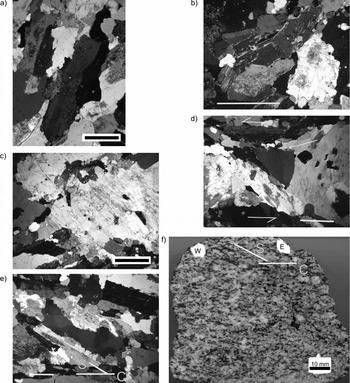
Essentially similar magmatic fabrics are occasionally preserved in low strain areas in the southeastern part of the Creag Mhór sheet and in the River Brora examples, but here the influence of solid-state deformation is much greater. Within these areas (e.g. Cnoc Arthur, NC 730 086), planar and linear fabric elements are parallel to S0/S1/S2 and L2, respectively (Fig. 5), but record solid-state deformation. Plagioclase and hornblende grains are generally subhedral with embayed grain boundaries (Fig. 9a), and are often broken (Fig. 9b), but cracks are only rarely healed by late magmatic minerals. Feldspars show bent twins, marginal recrystallization (Fig. 9c) and undulose extinction. Quartz occurs as recrystallized tails in pressure shadows (Fig. 9d) and ribbons that show evidence for subgrain development and grain boundary migration (Fig. 9e). In areas of high solid-state strain, centimetre-scale C-S fabrics indicate a top-to-the-W sense of shear parallel to L2 (Fig. 9f). The microstructures are consistent with deformation at temperatures of c. 550–400°C (Boullier & Bouchez, Reference Boullier and Bouchez1978; Tribe & D'Lemos, Reference Tribe and D'Lemos1996; Passchier & Trouw, Reference Passchier and Trouw2005 and references therein).
Evidence for solid-state deformation within the Creag Mhor quartz monzodiorite sheet at Cnoc Arthur [NC 730 086] (all samples cut parallel to mineral lineation): (a) subhedral plagioclase with irregular, embayed grain boundaries; (b) kinked and broken hornblende; also note irregular grain boundaries in feldspar; (c) subhedral K-feldspar showing marginal recrystallization and exsolution at intersecting K-feldspar grain boundaries; (d) recrystallized quartz in pressure shadow drawn out into foliation and giving top-to-the-W (left) sense of shear (half arrows); (e) recrystallized quartz aligned parallel to the S-fabric defined by earlier crystallized plagioclase; (f) polished slab with mafic minerals defining grain-scale S-C fabrics consistent with top-to-the-W shear during down-temperature deformation (W – west, E – east). Scale bar in (a–e) is 1 mm long.

4.c. Post-D2 emplacement of the central pluton
Two field observations imply that the central pluton was emplaced post-D2: firstly, the regional S0/S1/S2 foliation within the country rocks is reoriented significantly in the vicinity of the pluton (Fig. 6a), and secondly, although outer components of the pluton carry a foliation, this is not accompanied by any lineation that might correlate with L2 in the country rocks.
In a traverse towards the margin of the pluton, the outer quartz monzodiorite records systematic changes in fabric (Fig. 10). Away from the margin of the pluton, it carries a variably developed planar foliation defined by euhedral tabular plagioclase and prismatic hornblende with occasional eu- to subhedral alkali feldspar (Fig. 10a). Quartz occurs as approximately circular interstitial pools. Towards the pluton margin, high strain zones may develop where the fabric is progressively closer spaced, grain size may be reduced and the crystal habit is subhedral (Fig. 10b, c). The constituent phases show straight grain boundaries and together with interstitial ovoid to elongate quartz pools form an interlocking framework that we interpret as a pre-rheologically critical melt percentage fabric (pre-RCMP; e.g. Tribe & D'Lemos, Reference Tribe and D'Lemos1996). Bent plagioclase and marginal recrystallization of feldspar are interpreted to result from solid-state deformation at c. 650°C. Locally abundant micrographic and myrmekitic intergrowths are interpreted to result from strain-induced recrystallization at c. 600–550°C (Simpson, Reference Simpson1985). Quartz grains within the low strain ovoid interstitial positions are generally undeformed whereas elongate quartz ribbons occur between tabular feldspar crystals. However, they show no microstructural evidence for high-temperature grain boundary migration recrystallization, but are characterized by undulose extinction and the development of internal prismatic deformation bands formed by subgrain rotation at moderate to lower temperatures of about 500–400°C (Drury & Urai, Reference Drury and Urai1990; Hirth & Tullis, Reference Hirth and Tullis1992; Tribe & D'Lemos, Reference Tribe and D'Lemos1996; Stipp et al. Reference Stipp, Stünitz, Heilbronner and Schmid2002). In summary, the formation of the pervasive foliation occurred in the magmatic state and was followed by coaxial flattening and minor high- to moderate-temperature solid-state recrystallization which did not significantly reorientate the primary fabric.
Polished slabs showing progressive pre-RCMP fabric development in the outer quartz monzodiorite in a traverse towards the NE margin of the central pluton: (a) weak alignment of K-feldspar, plagioclase and hornblende, note the circular interstitial quartz pools (arrows); (b) fabric is more prominent, defined by hornblende and euhedral to subhedral plagioclase; interstitial quartz pools are oval-shaped; (c) well-developed fabric defined by subhedral to oval aggregates of plagioclase and quartz that are aligned parallel to small but euhedral grains of hornblende. Black dot is 5 mm in diameter.

In outcrop, the porphyritic granodiorite is characterized by a coarse-grained, slightly anastomosing foliation defined by the alignment of eu- to subhedral, small tabular plagioclase, large, eu- to subhedral porphyritic alkali feldspar and hornblende (Fig. 4b). Interstitial spaces are occupied by large, generally ovoid multigrain quartz pools. In thin-section, the minerals show similar magmatic-state features as described for the quartz monzodiorite, preserving prismatic grain shapes, shape-preferred orientations and igneous grain contacts. Evidence for a down-temperature solid-state overprint (e.g. marginal recrystallization of feldspars and myrmekite development) is similarly present. However, the interstitial multigrain quartz aggregates are largely undeformed. Recrystallization of hornblende to biotite is common and may have occurred at lower-greenschist-facies temperatures. Overall, the features are consistent with magmatic-state, pre-RCMP foliation development and subsequent largely undisturbed cooling. In contrast to the quartz monzodiorite and the granodiorite, the inner biotite granite does not carry any tectonic or magmatic foliations.
In summary, the quartz monzodiorite and granodiorite components of the central pluton are dominated by magmatic fabrics that were modified by weak down-temperature solid-state recrystallization and coaxial strain during cooling. The microstructural observations are therefore consistent with the field evidence that the central pluton was emplaced post-D2 (see also Soper, Reference Soper1963).
5. U–Pb geochronology
The only available geochronological data relating to the age of the Rogart igneous complex is a K–Ar whole-rock age of c. 420 Ma (Brown, Miller & Gresty, Reference Brown, Miller and Gresty1968). In order to constrain more precisely its age of emplacement, zircons were analysed from a sample of the outer quartz monzodiorite of the central pluton collected at [NC 7095 0295].
5.a. Sample preparation procedure and analytical techniques
The outer quartz monzodiorite of the central pluton was dated using the U–Pb technique. A sample of c. 30 kg was jaw crushed and disc milled and the < 400 micron fraction sieved out. Heavy mineral concentrates were obtained using a Gemini shaking table, followed by a superpanner. A > 3.3 g/ml density separate was recovered using Di-iodomethane and the minerals separated magnetically using a Frantz LB-1 magnetic separator. The recovered zircons were hand picked under alcohol and then air abraded. U and Pb separations followed the procedures of Krogh (Reference Krogh1973) with minor modifications of Corfu & Ayres (Reference Corfu and Ayres1984). Fractions were spiked with a mixed 205Pb/235U isotopic tracer (Krogh & Davis, Reference Krogh and Davis1975) before digestion and chemical analysis. U and Pb were loaded onto outgassed single Re filaments with silica gel and were analysed on a VG 354 mass spectrometer using a Daly detector following Noble, Tucker & Pharaoh (Reference Noble, Tucker and Pharaoh1993). Chemistry blanks were c. 5 pg, and these were monitored in each batch of chemistry. Uranium blanks were < 0.1 pg U. All results and errors were calculated following Ludwig (Reference Ludwig1993, Reference Ludwig1994) and the Pb isotope ratios were corrected for initial common Pb in excess of laboratory blank using the Stacey & Kramers model (Reference Stacey and Kramers1975). Ages were calculated using the decay constants of Jaffey et al. (Reference Jaffey, Flynn, Glendenin, Bentley and Essling1971). The 2σ errors (95% confidence levels) given in Table 1 for ages and isotope ratios were obtained by propagating key sources of error through all calculations following the methods using Ludwig (Reference Ludwig1993, Reference Ludwig1994).
Analytical data for the U–Pb zircon analyses from the Rogart granite

† Sample weights and hence of U and Pb concentrations are approximate.
‡ Measured ratios are corrected for fractionation and common Pb spike.
§ Corrected for fractionation, spike, laboratory blank and initial common Pb using calculated at 425 Ma (Stacey & Kramers, Reference Stacey and Kramers1975).
** Correlation coefficients of 207Pb/235Pb and 206Pb/235U are calculated using procedures and algorithms of Ludwig (Reference Ludwig1993). Errors for the measured ratios are propagated through data reduction and quoted at the 2σ level.
5.b. Results
Three zircon fractions plot on or just below concordia and give a concordant 207Pb/235U – 206Pb/238U age of 425±1.5 Ma (2σ) for crystallization of the intrusion (Fig. 11). Data are presented in Table 1.
U–Pb concordant zircon age from the outer quartz monzodiorite of the central pluton. The MSWD is of concordance and equivalence at 2σ and takes into account errors on the decay constant. The dashed ellipses are the weighted mean error ellipse of the data points.

6. Emplacement model for the Rogart igneous complex
The syn-D2 leucogranites and late-D2 quartz monzodiorites are strikingly similar in their structural setting to granitic sheets that further north in central Sutherland were emplaced during D2 (Holdsworth & Strachan, Reference Holdsworth and Strachan1988; Kinny et al. Reference Kinny, Strachan, Rogers, Friend and Kocks2003). The location of these variably deformed intrusions in both central and SE Sutherland within the immediate footwall of the Naver Thrust suggests that this structure played an important role in channelling mantle- and crustal-derived melts during Scandian nappe stacking. Similarly, the D2 Skinsdale Thrust in E Sutherland and Caithness appears to have acted as a fundamental structural control on emplacement of the Strath Halladale Granite (Kocks, Strachan & Evans, Reference Kocks, Strachan and Evans2006). Leucogranites and associated injection migmatites are, however, only found associated with the Rogart igneous complex, and their spatial coincidence suggests some form of genetic relationship. We suggest that leucogranite melts were generated during D2 crustal thickening in response to heat and fluid influx from ascending mantle-derived magmas, which resulted in melting of Moine semi-pelitic rocks at lower structural levels. The field relations of the leucogranites are consistent with pervasive flow through actively deforming ductile crust, with injection of centimetre–metre-scale melt sheets along previously formed anisotropies and newly developed thrusts (e.g. Collins & Sawyer, Reference Collins and Sawyer1996; Brown & Solar, Reference Brown and Solar1999; Weinberg & Searle, Reference Weinberg and Searle1998). In contrast, the slightly younger late-D2 quartz monzodiorite sheets were emplaced as coherent bodies.
The post-D2 Rogart central pluton is completely different in its structure and field relations. Two different scenarios are commonly invoked to explain the emplacement of such sub-circular to elliptical, compositionally zoned plutons that contain concentric fabric patterns and show a deformed wall rock envelope. The first is that the pluton represents a diapir that rose vertically through the crust as a pre-assembled pluton that deformed its wall rocks on the way to its final location (e.g. Paterson & Vernon, Reference Paterson and Vernon1995; Miller & Paterson, Reference Miller and Paterson1999). Alternatively, it could represent a pluton that evolved more or less in situ by rapid additions of batches of magma at the site of emplacement leading to inflation and lateral expansion (‘ballooning’) of the intrusion (e.g. Petford, Kerr & Lister, Reference Petford, Kerr and Lister1993; Clemens, Petford & Mawer, Reference Clemens, Petford, Mawer and Holness1997; Molyneux & Hutton, Reference Molyneux and Hutton2000). Various field criteria might distinguish between these two models, although they may not be unequivocal or exclusive (Miller & Paterson, Reference Miller and Paterson1999; Molyneux & Hutton, Reference Molyneux and Hutton2000). Nonetheless, structural features of the Rogart central pluton and its host rocks are inconsistent with the diapiric interpretation. Diagnostic features such as steep magmatic lineations, margin-parallel foliations with pluton-up kinematic indicators, steep high-temperature marginal shear zones and a well-developed rim syncline are absent. Instead, the development within the pluton of a pervasive magmatic-state foliation, local subhorizontal or shallowly plunging (non-radial) lineations, and oblate mafic enclaves suggest a subhorizontal flattening strain during emplacement, consistent with in situ inflation and lateral expansion.
We suggest that the Rogart central pluton was assembled by successive batches of magma that were channelled up an actively deforming fault zone that was later reactivated to form the Strath Fleet Fault. Pluton emplacement may have been facilitated by development of a localized dilational jog or pull-apart structure into which magma was injected forcefully to result in the observed pluton fabric patterns and reorientation of host rock foliations. The role of steep strike-slip faults in controlling the ascent and emplacement of magmas has been highlighted by numerous workers (e.g. Hutton, Reference Hutton1988 b; D'Lemos, Brown & Strachan, Reference D'Lemos, Brown and Strachan1992; Hutton & Reavy, Reference Hutton and Reavy1992; Tikoff & Tessyier, Reference Tikoff and Tessyier1992; Jacques & Reavy, Reference Jacques and Reavy1994; Karlstrom & Williams, Reference Karlstrom and Williams1995). Although we have no geophysical data, we envisage that the pluton was originally tabular with a gently inclined roof and floor. The map-scale clockwise swing of Moine foliations in the vicinity of the Strath Fleet Fault (Fig. 5a), and the sense of obliquity between the fault and the long axis of the pluton are features consistent with emplacement during dextral shear. This is kinematically compatible with sinistral shear along the Great Glen Fault if displacements along the two structures were contemporaneous (Johnson & Frost, Reference Johnson and Frost1977; Watson, Reference Watson1984). However, these dextral movements cannot have been substantial as further west there is no significant offset of regional foliation trends and structures either side of the Loch Shin Line.
7. Conclusions
The Rogart igneous complex is unique within the Scottish Caledonides because it comprises an apparent continuum of genetically related magma types that records a progressive change in emplacement mechanisms related to large-scale tectonic controls. Syn-D2 leucogranites and slightly younger late-D2 quartz monzodiorites were emplaced during crustal thickening and focused within the broad zone of ductile deformation associated with the Naver Thrust. In contrast, emplacement of the post-D2 composite central pluton appears to have been controlled by development of a steeply dipping dextral shear zone along the Loch Shin Line. There is no evidence for any significant hiatus in magma emplacement. The mantle-derived nature of the late-to-post-D2 melts implies that the Naver Thrust and the Loch Shin Line were both crustal-scale structures along which magmas were channelled during deformation.
The results of the geochronology study reported here place constraints on the timing of regional tectonic events. The new U–Pb zircon age of 425±1.5 Ma for the post-D2 Rogart central pluton represents an upper limit on the timing of D2 ductile thrusting and associated deformation and amphibolite-facies metamorphism within this part of the Caledonides. The cessation of D2 is now tightly bracketed between the age of the Rogart central pluton and that of the only slightly older syn-to-late-D2 Strath Halladale Granite (426±2 Ma; Kocks, Strachan & Evans, Reference Kocks, Strachan and Evans2006). The new age for the Rogart central pluton also provides indirect constraints on the age of marginal thrusting, specifically within the ‘Assynt bulge’ in the Moine Thrust Zone further west. The broad arcuate swing of D2 fabrics within the Moines that resulted from the formation of this structure is disrupted and reoriented in the envelope of the Rogart central pluton. It therefore seems clear that the main displacements along the Moine, Ben More and Glencoul thrusts in the Assynt area must have been essentially complete before the Rogart central pluton was emplaced. This is consistent with the view that the main displacements in the Moine Thrust Zone occurred at c. 435–430 Ma (Johnson et al. Reference Johnson, Kelley, Oliver and Winter1985; Kelley, Reference Kelley1988; Freeman et al. Reference Freeman, Butler, Cliff and Rex1998; Goodenough et al. Reference Goodenough, Millar, Strachan, Krabbendam and Evans2011). Any Early Devonian displacements (Freeman et al. Reference Freeman, Butler, Cliff and Rex1998) must have been very limited.
The Rogart central pluton is essentially the same age as the Ratagain, Strontian and Clunes plutons that were emplaced during regional strike-slip faulting along the NE-trending Great Glen Fault system (Fig. 1; Hutton, Reference Hutton1988b ; Hutton & McErlean, Reference Hutton and McErlean1991; Stewart et al. Reference Stewart, Strachan, Martin and Holdsworth2001). In the Grampian Highlands to the east, emplacement of the similar-aged Etive–Glencoe–Rannoch Moor–Strath Ossian plutons has also been related to late Caledonian sinistral strike-slip faulting (Jacques & Reavy, Reference Jacques and Reavy1994) as has the Etive Dyke Swarm (Morris & Hutton, Reference Morris and Hutton1993; Morris, Page & Martinez, Reference Morris, Page and Martinez2005). All these plutons share a number of structural features, including steeply dipping margins and well-developed magmatic-state fabrics. The model proposed here for emplacement of the Rogart pluton, involving intrusion and progressive assembly by ballooning within a dilational jog developed during dextral shear along the NW-trending Loch Shin Line, supports the interpretation that this structure is an anti-Riedel shear to the Great Glen Fault system (Johnson & Frost, Reference Johnson and Frost1977; Watson, Reference Watson1984). The Rogart and Ratagain plutons are of particular importance because in both cases they demonstrably post-date ductile, thrust-related fabrics in their host rocks, and were emplaced along brittle faults that are related to the Great Glen Fault system. The timing is similar to that envisaged in NW Ireland where a major splay of the Great Glen Fault (the Leannan Fault) has magma emplaced along it at 422±2 Ma during sinistral strike-slip tectonics (Kirkland, Alsop & Prave, Reference Kirkland, Alsop and Prave2008). These findings are consistent with the view that a fundamental change in tectonic regime occurred in the Scottish Caledonides at around 425 Ma, corresponding to the switch from regional thrusting that resulted from the oblique collision of Baltica and Laurentia, to the development of the orogen-parallel, sinistral Great Glen Fault system. By analogy with the present-day Himalayas, such a change could correspond to the transition from collision to lateral ‘escape tectonics’, although in the case of the Caledonides it has been modelled in terms of progressively changing relative plate motions between Baltica–Avalonia and Laurentia (Dewey & Strachan, Reference Dewey and Strachan2003).
Acknowledgements
HK acknowledges a postgraduate studentship held at Oxford Brookes University. Isotopic dating was funded by a grant from the steering committee of the NERC Isotope Geosciences Laboratory. The authors thank Kathryn Goodenough and Ian Alsop for constructive reviews that improved the paper.