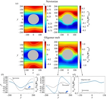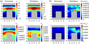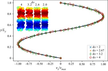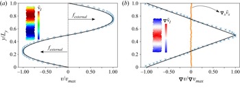

1. Introduction
The modelling of complex fluids, synthetic or biological, is in general a challenging task due to the multiscale nature of the flow, leading to complex behaviours such as flow-induced phase separation, shear-thinning/thickening and viscoelasticity. Usual approaches involve the solution of a macroscopic balance of momentum, along with constitutive equations that relate the dependency of the stresses and velocity fields due to microscopically originated features. However, limitations of these approaches arise when the constitutive equations are not known a priori. Moreover, the existence of large relaxation times at the microscale results in a non-trivial interplay with macroscopic flow features, requiring a detailed description of the entire stress history. In this context, heterogeneous multiscale methods (HMMs) (Ee et al. Reference Ee, Engquist, Li, Ren and Vanden-Eijnden2007) that combine numerical algorithms to resolve separately macro- and microscales, appear as powerful tools to model the behaviour of fluids across scales. In HMMs, microscales are localized and solved on parts of the domain to obtain microscopically derived properties that are used to close the macroscale problem (Ren & Weinan Reference Ren and Weinan2005). This methodology offers the advantage of capturing microscopic effects at the macroscopic length scales, with a lower cost than solving the full microscale problem in the whole domain. In HMMs, the derived microscales properties can enter into the macroscales representations either through constitutive relationships or microscopic stresses information without a priori assumption of the constitutive relationships. The latest is an important advantage of HMMs for the modelling of complex fluids. For an extended review on HMMs, the reader is referred to the work of Ee et al. (Reference Ee, Engquist, Li, Ren and Vanden-Eijnden2007). One of the key benefits of having a constitutive equation for stress is the ability to generalize fluid behaviour in the macroscopic domain without the need for explicit microscopic simulations. Such constitutive relations have been formulated for various non-Newtonian fluids (Bird et al. Reference Bird, Curtiss, Amstrong and Ole1987). However, many complex systems lack an a priori constitutive relationship, which necessitates system-specific approximations. In this context, using microscopically informed stress for the momentum equation provides a more systematic approach to bypass the need for unknown constitutive models. The primary assumption with this strategy is that the adopted methodology used for the microscales should be capable of reproducing the physical system. Consequently, the microscales will typically require preliminary characterization.
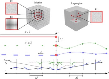
Depending on the type of discretization (Eulerian or Lagrangian) used for macro- and microscales, the HMMs are classified as Eulerian/Eulerian (EE), Lagrangian/Lagrangian (LL), Eulerian/Lagrangian (EL) and Lagrangian/Eulerian (LE); see figure 1(a). A large part of the existent HMMs relies on EE and EL schemes (Ee et al. Reference Ee, Engquist, Li, Ren and Vanden-Eijnden2007), where the macroscale dynamics is resolved on a fixed grid (using a variety of methods such as finite elements, finite volumes, lattice Boltzmann, to name a few), and microscale simulations (e.g. molecular dynamics (Alexiadis et al. Reference Alexiadis, Lockerby, Borg and Reese2013; Borg, Lockerby & Reese Reference Borg, Lockerby and Reese2015; Tedeschi et al. Reference Tedeschi, Giusteri, Yelash, Lukácová-Medvid'ová, Tedeschi, Giusteri, Yelash and Lukácová-Medvid'ová2021), coarse-graining methods, stochastic methods, etc.) are associated with grid points, where microscopic properties are derived. For viscoelastic fluids modelling, Laso and Öttinger introduced a pioneering approach known as CONNFFESSIT (Laso & Öttinger Reference Laso and Öttinger1993) (calculation of non-Newtonian flow: finite element and stochastic simulation technique), combining finite elements at the macroscale and stochastic particle simulations of polymer dynamics at the microscale.
Scheme of different HMM approaches. Eulerian–Eulerian (EE), Eulerian–Lagrangian (EL) and Lagrangian–Lagrangian (LL). The evolution of the stress tensor depends on the effective relaxation times at the microscales  $\lambda '$. Systems with
 $\lambda ' \ll \bar {\lambda }$ (green) are accurately computed at the microscopic scales, whereas for
 $\lambda ' \leq \bar {\lambda }$ (blue), larger microscale simulations are required to capture memory effects as the macro scales evolve. LL approaches facilitate the carrying of the stress information during the time integration at macroscales.

The EE and EL approaches are generally appropriate for fluids with microstructural relaxation times ( ${\lambda }'$) that are sufficiently small compared to the macroscopic ones (
 ${\lambda }$) (Ren & Weinan Reference Ren and Weinan2005; Yasuda & Yamamoto Reference Yasuda and Yamamoto2008, Reference Yasuda and Yamamoto2014). As shown in figure 1(b), for multiscale problems with significant time scale separation, where
 ${\lambda }' \ll {\lambda }$ (or
 $Wi = {\lambda }'/ {\lambda } \ll 1$, where
 $Wi$ is the Weissenberg number), a quasi-steady state can be achieved for the microscopic stresses, regardless of the flow history. This approach has been employed in atomistic-continuum simulations of simple fluids using molecular dynamics with an Eulerian grid-based calculation of the flow field (Ren & Weinan Reference Ren and Weinan2005). In simple fluids, the local stress depends point-wise in time on the velocity gradient, and therefore, the initial conditions for the microstructure can be chosen arbitrarily at each time step. The average stress is then calculated using the Irving–Kirkwood approximation, provided that local stationarity is achieved within the same time step.
However, this approach cannot be extended to complex fluids with finite memory, when  ${\lambda } \lesssim {\lambda }'$ (
 $Wi>1$). As shown in figure 1(b), the stresses and microstructure heavily depend on flow history, and relaxation times are likely to be comparable to, or even exceed, the macroscopic time step. The direct use of EL or EE schemes to generate an initial microstructural configuration in a fixed fluid cell is fundamentally and technically limited due to two reasons. First, it is not known beforehand where the fluid comes from and what its flow history was, and second, even if this information were available, it would require additional constitutive and numerical features capable of accounting for complex spatio/temporal variations.
Alternative techniques to address these issues include spatial/temporal homogenization methods and backward-tracking Lagrangian particles combined with Eulerian grids to capture memory effects in the fluid (Phillips & Williams Reference Phillips and Williams1999; Wapperom, Keunings & Legat Reference Wapperom, Keunings and Legat2000; Ingelsten et al. Reference Ingelsten, Mark, Kadar and Edelvik2021). However, fluid memory can be very long in polymer systems, suspensions, etc., precluding simple linear backward approximations. Regarding the second issue, one alternative is to incorporate continuum configuration fields that can be discretized and advected from the macroscales (Ottinger, van den Brule & Hulsen Reference Öttinger, van den Brule and Hulsen1997). However, it would be extremely challenging to know a priori those fields for general multiphysics problems (i.e. non-polymeric), as well as the numerical generation of microscopic configurations consistent with the history of the fluid.
For systems with larger microstructural relaxation times ( ${\lambda } \lesssim {\lambda }'$), the particular restrictions of EE and EL can be circumvented using fully Lagrangian, LL, schemes (Ee et al. Reference Ee, Engquist, Li, Ren and Vanden-Eijnden2007), and a proper sampling procedure for the microstructure. Indeed, LL schemes have been successfully used to model elastic effect and history-dependent flows (Murashima & Taniguchi Reference Murashima and Taniguchi2010; Seryo et al. Reference Seryo, Sato, Molina and Taniguchi2020; Morii & Kawakatsu Reference Morii and Kawakatsu2021) at large Weissenberg numbers. As illustrated in figure 1(b), LL schemes directly track the material points at the macroscale retaining their strain and strain-rate variation, thus naturally handling history-dependent fluids. A variety of LL methodologies have emerged over the last decade, adopting mainly smoothed particle hydrodynamics (SPH) discretizations at the macroscales and combination of different microscopic models (Ellero, Español & Flekkoy Reference Ellero, Español and Flekkoy2003; Murashima & Taniguchi Reference Murashima and Taniguchi2010; Feng et al. Reference Feng, Andreev, Pilyugina and Schieber2016; Xu & Yu Reference Xu and Yu2016; Sato & Taniguchi Reference Sato and Taniguchi2017; Zhao et al. Reference Zhao, Li, Caswell, Ouyang and Karniadakis2018; Sato, Harada & Taniguchi Reference Sato, Harada and Taniguchi2019; Giessen et al. Reference Giessen2020; Schieber & Hütter Reference Schieber and Hütter2020; Seryo et al. Reference Seryo, Sato, Molina and Taniguchi2020; Morii & Kawakatsu Reference Morii and Kawakatsu2021). At the microscales, the stress evolution of polymeric solutions and entanglements have been accounted for using Brownian dynamic (Xu & Yu Reference Xu and Yu2016), active learning (Zhao et al. Reference Zhao, Li, Caswell, Ouyang and Karniadakis2018; Seryo et al. Reference Seryo, Sato, Molina and Taniguchi2020) and slip-link models (Feng et al. Reference Feng, Andreev, Pilyugina and Schieber2016; Sato & Taniguchi Reference Sato and Taniguchi2017; Sato et al. Reference Sato, Harada and Taniguchi2019). In these LL schemes, it is considered that microscales only account for the polymer contribution to the stress, whereas the fluid is modelled uniquely from the macroscopic discretization (Feng et al. Reference Feng, Andreev, Pilyugina and Schieber2016). Its effect (i.e. velocity gradient tensor) enters the Langevin-type dynamics for stochastic micro-realizations implicitly as a single parameter, and not directly as a boundary condition for the full microsystem.
In fact, one important issue limiting the applicability of HMM methods to more detailed descriptions of complex fluids is precisely the proper imposition of microscale constraints that are consistent with the macroscale kinematics and the calculation of microscopic information required by the macro state (Ee et al. Reference Ee, Engquist, Li, Ren and Vanden-Eijnden2007). When using particle-based micro-models with explicit solvent description (e.g. molecular dynamics, dissipative particle dynamics, discrete element method, SDPD), the construction of this constrained microscale solver represents often the most cumbersome technical step. For LL schemes, due to the history-dependent evolution of the flow and the existence of non-trivial flow configurations, the microscales can be subjected to arbitrary series of deformations that are usually difficult to handle with traditional periodic boundary conditions (BCs). To avoid these limitations, existent LL schemes have been restricted to the use of microscopic simulators that do not depend on the ‘physical’ boundary conditions (Feng et al. Reference Feng, Andreev, Pilyugina and Schieber2016; Sato & Taniguchi Reference Sato and Taniguchi2017; Sato et al. Reference Sato, Harada and Taniguchi2019; Morii & Kawakatsu Reference Morii and Kawakatsu2021). This includes, for example, the case of Brownian dynamics for statistically independent polymers, such as dilute polymer solutions or polymer melts in mean field approximation, or where geometries that reproduce simple flow configurations are utilized (Seryo et al. Reference Seryo, Sato, Molina and Taniguchi2020) (i.e. simple shear or uniaxial deformation). More general micro–macro couplings (e.g. full particle-based model of polymeric dispersions, colloid suspensions, emulsions, etc.) involving detailed microsystems models undergoing arbitrary flow deformations are beyond the capabilities of the current frameworks.
Another important assumption in some of the existent microsolvers is that the microscopic states of all polymers are in equilibrium and that the coils do not have translational degrees of freedom, but only rotational and extensional ones (Morii & Kawakatsu Reference Morii and Kawakatsu2021). Regarding microscopic BCs approaches using simple flow configurations, they are suitable to account for translational effects and often provide information sufficient to characterize simple fluids. However, since complex fluids can possess microscopic structures that are influenced by different flow configurations, geometries, time scales and deformation rates, it has been evidenced that to correctly model non-Newtonian fluids (Tedeschi et al. Reference Tedeschi, Giusteri, Yelash, Lukácová-Medvid'ová, Tedeschi, Giusteri, Yelash and Lukácová-Medvid'ová2021), it is necessary to determine the full stress contribution from the microscopic solver.
In this manuscript, we propose a generalized fully Lagrangian HMM (LHMM) using smoothed dissipative particle dynamics (Español & Revenga Reference Español and Revenga2003; Ellero & Español Reference Ellero and Español2018) (SDPD), suitable to model general complex fluids (e.g. colloids, polymer, microstructures in suspensions) while using the same fluid description across scales. Among the different computational methods successfully used to model Newtonian and non-Newtonian fluids at continuum and microscales, SDPD has emerged as a suitable tool to simulate complex fluids (Kulkarni et al. Reference Kulkarni, Fu, Shell and Leal2013; Müller, Fedosov & Gompper Reference Müller, Fedosov and Gompper2014; Ellero & Español Reference Ellero and Español2018). The main strengths of SDPD are: (i) it consistently discretizes the fluctuating Navier–Stokes equations allowing the direct specification of transport properties such as viscosity of the fluid; (ii) SDPD is compliant with the general equation for non-equilibrium reversible–irreversible coupling (GENERIC) (Öttinger Reference Öttinger2005) and therefore, it discretely satisfies the first and second laws of thermodynamics, and fluctuation–dissipation theorem (FDT); (iii) at macroscopic scales, SDPD converges to the well-known continuum method smoothed particle hydrodynamics (SPH) as the characteristic size of the discretized particle increases (Vázquez-Quesada, Ellero & Español Reference Vázquez-Quesada, Ellero and Español2009; Ellero & Español Reference Ellero and Español2018). For an extended review of SDPD, the reader is referred to the publication of Ellero & Español (Reference Ellero and Español2018).
Since SDPD offers a natural physical link between different scales, we construct an HMM that uses SDPD to solve both macro- and microscales. This approach ensures the compatibility of the different representations by construction and physical consistency across scales. At the microscales, we adopt the recently proposed BC methodology (Moreno & Ellero Reference Moreno and Ellero2021) that allows the acquisition of the full microscopic stress contributions for arbitrary flow configurations. This allows to carry out micro-computations under general mixed flow conditions. While it is true that CONNFFESSIT (Laso & Öttinger Reference Laso and Öttinger1993) and other EL methodologies are also capable of handling mixed flow features, those features are not included in current LL methodologies with fully explicit solvent descriptions. Furthermore, in the context of LL, our approach exploits the versatility of SDPD to model a variety of microscopic physical systems beyond polymeric systems. Our LHMM scheme's strength lies in its unique combination of aspects that other methods only partially account for. We can summarize the main features of the proposed LHHM framework as follows.
(i) Model history-dependent flows by construction.
(ii) Significant spatio-temporal gains in simulations compared with fully resolved microscale simulations.
(iii) Thermodynamic-consistent discretization of the fluctuating Navier–Stokes equations in both macro- and microscales (deterministic–stochastic) providing a direct link to physical parameters.
(iv) GENERIC compliant at both macro and micro levels.
(v) Multiphysics – polymers, colloids, suspensions, multiphasic systems. No constitutive models for closure are required.
(vi) Complex-flow configurations are allowed and can be handled at the microscales.
In the following sections, first, a general description of HMM is introduced along with the governing balance equations, then, the proposed fully Lagrangian approach and the particle-based discretization are presented. Finally, without loss of generality, we streamline the validation of the methodology focusing on two-dimensional simulations of complex flows with memory. At the microscales, we adopt generic, yet complex, polymeric and multiphase flows to showcase the flexibility of the method.
2. Heterogeneous multiscale methods
In general, for HMMs, we can define the macroscopic problem considering a domain  $\varOmega \subset \mathcal {R}^D$ (with dimension
 $D=2,3$) with a boundary
 $\partial \varOmega = \varGamma _{\mathcal {D}} \cup \varGamma _{\mathcal {N}}$, where
 $\varGamma _{\mathcal {D}}$ and
 $\varGamma _{\mathcal {N}}$ correspond to boundary regions where Dirichlet and Neumann boundary conditions are applied, respectively. The mass and momentum balance of the system for an incompressible fluid with constant density
 $\rho$ can be expressed as
 \begin{equation} \left. \begin{aligned} \boldsymbol{\nabla} \boldsymbol{\cdot} {\boldsymbol{v}} & = 0, \quad \text{in} \ \varOmega \times (0,T),\\ \rho \frac{\text{d} {\boldsymbol{v}}}{\text{d} t} - \boldsymbol{\nabla} \boldsymbol{\cdot} \boldsymbol\tau({\boldsymbol{v}},p) & = f ,\quad \text{in} \ \varOmega \times (0,T),\\ {\boldsymbol{v}} & = g, \quad \text{on} \ \varGamma_{\mathcal{D}} \times (0,T), \\ {\boldsymbol{v}}(0) & = {\boldsymbol{v}}_0, \quad \text{in} \ \varOmega \times \{0\}, \end{aligned} \right\} \end{equation}
where the total stress tensor is given by  ${\boldsymbol \tau } = -p{\boldsymbol I} + \boldsymbol {\pi }$, with
 $p$ being the pressure and
 $\boldsymbol {\pi }$ the viscous stress. For incompressible Newtonian fluids, the viscous stress is a linear function of the strain rate (
 $\boldsymbol {\pi }=\eta (\boldsymbol {\nabla }{\boldsymbol v} + \boldsymbol {\nabla }{\boldsymbol v}^T)$, with
 $\eta$ being the viscosity) and the flow can be totally described using (2.1). For non-Newtonian fluids such as colloidal and polymeric systems, this linear behaviour does not hold and other relationships are required (Bird et al. Reference Bird, Curtiss, Amstrong and Ole1987). Additionally, for microfluidics, where complex flow patterns and thermal effects may arise, the use of Dirichlet boundary conditions,
 ${\boldsymbol {v}} = g$ on
 $\varGamma _{\mathcal {D}} \times (0,T)$, may not accurately model such microscopic effects, requiring more elaborated considerations for the boundary conditions.
2.1. Lagrangian heterogeneous multiscale method (LHMM)
We propose an LL-type of methodology, as depicted in figure 1, discretizing both macro- and microscales with a particle-based representation of the system. We distinguish macroscale parameters and variables if they are derived from microscales calculations using the upper bar (i.e.  $\bar {X}$), whereas microscale variables are denoted using a prime (i.e.
 $X'$). We use the subindices
 $x,y$ and
 $z$ to indicate the coordinate axis. If we express the macroscopic viscous stress determined from a representative microscopic domain
 $\varOmega '$ in terms of hydrodynamic, non-hydrodynamic and kinetic contributions as
 ${\bar {\boldsymbol {\pi }}}={\bar {\boldsymbol {\pi }}}_{h}+{\bar {\boldsymbol {\pi }}}_{m}+{\bar {\boldsymbol {\pi }}}_{k}$, the ensemble average stress at the microscales leads to
 \begin{align} \langle \bar{\boldsymbol{\pi}} \rangle (\boldsymbol x) &= \frac{1}{\varOmega'} \int_{\varOmega'}{\boldsymbol{\pi}'} \,\text{d} \varOmega', \nonumber\\ &= \frac{1}{\varOmega'} \left(\int_{\varOmega'} {\boldsymbol{\pi}}_h' \,\text{d} \varOmega' + \int_{\varOmega'} {\boldsymbol{\pi}}_m' \,\text{d} \varOmega' + \int_{\varOmega'} {\boldsymbol{\pi}}_k' \,\text{d} \varOmega' \right), \end{align}
where  ${\boldsymbol {\pi }}_h'$ accounts for the hydrodynamic contributions to the stress and
 ${\boldsymbol {\pi }}_m'$ corresponds to the non-hydrodynamics effects (presence of colloids, polymers, walls, etc). The
 $\langle \boldsymbol {\cdot }\rangle$ denotes the averaging over the microscopic domain. However, the
 $\bar {\boldsymbol {\pi }}$ corresponds to a macroscopic field. For a Newtonian (ideal) solvent, the stress is given by
 $\langle \bar {\boldsymbol {\pi }}_o\rangle = <2\eta \bar {\boldsymbol {d}}> = \langle \bar {\boldsymbol {\pi }}_h\rangle$ (
 $\bar {\boldsymbol {d}}$ being the rate-of-strain tensor computed from microscopic information). Additionally, if this Newtonian solvent stress contributes homogeneously over the whole domain at all scales, it is reasonable to consider that
 ${\boldsymbol {\pi }}_o = 2 \eta \boldsymbol {d} =\langle \bar {\boldsymbol {\pi }}_o\rangle$. (Notice that the overbar notation of
 $\boldsymbol {d}$ is omitted since is not a multiscale contribution, in contrast to
 $\bar {\boldsymbol {d}}$ that is a macroscopic rate of strain determined from microscopic variables.) We can now introduce a hybrid macro–micro formulation given by
 \begin{equation}
\langle{\bar{\boldsymbol{\pi}}}_{h}\rangle (\boldsymbol x)
= \underbrace{\epsilon 2 \eta
\boldsymbol{d}}_{\textit{macro}} +
\underbrace{\frac{1}{\varOmega'} \int_{\varOmega'}
(1-\epsilon) {\boldsymbol{\pi}}_h' \,\text{d}
\varOmega'}_{\textit{micro}}.
\end{equation}
This scheme is a generalized framework that allows us to incorporate ideal hydrodynamics interactions of the fluid from both scales. The weighting parameter  $\epsilon$ conveniently provides numerical stability to the method, whereas naturally accounting for spatial inhomogeneities of the stresses. According to (2.3), if
 $\epsilon =1$, the ideal hydrodynamic contributions are fully accounted for from the macroscale level, and microscales only contribute to non-hydrodynamic interactions. In contrast, if
 $\epsilon =0$, the viscous stresses used to solve the macroscale problem are totally computed by the micro-representation, and it implicitly accounts for all stress contributions (hydro- and non-hydrodynamic) across scales. The balance between the origin of the Newtonian contribution to the stress, whether from macro- or microscales, can be controlled by the parameter
 $\epsilon$. Traditionally, Newtonian contributions have only been modelled from macroscales (
 $\epsilon =1$) as in previous work by other researchers (Murashima & Taniguchi Reference Murashima and Taniguchi2010; Feng et al. Reference Feng, Andreev, Pilyugina and Schieber2016; Xu & Yu Reference Xu and Yu2016; Sato & Taniguchi Reference Sato and Taniguchi2017; Zhao et al. Reference Zhao, Li, Caswell, Ouyang and Karniadakis2018; Sato et al. Reference Sato, Harada and Taniguchi2019; Schieber & Hütter Reference Schieber and Hütter2020; Seryo et al. Reference Seryo, Sato, Molina and Taniguchi2020; Morii & Kawakatsu Reference Morii and Kawakatsu2021). Microscopic simulations have generally been used to reproduce only the complex microstructural features without incorporating the Newtonian contributions. In contrast, our proposed framework uses the SDPD method at both scales, which consistently discretizes the Navier–Stokes equation. As a result, our method is theoretically capable of retrieving the ideal solvent stress contribution from microscales as well. Although this would not be needed for dispersed systems in Newtonian media undergoing affine deformations, it could be relevant in most complex cases considering non-Newtonian materials (Einarsson, Yang & Shaqfeh Reference Einarsson, Yang and Shaqfeh2018) or non-affine polymer deformations (Simavilla, Espanol & Ellero Reference Simavilla, Espanol and Ellero2023).
A major limitation associated with using only microscopic simulations to determine both hydrodynamic and non-hydrodynamic contributions ( $\epsilon =0$) can be related to the numerical stability of the method. The computation of the stress involves spatial and temporal averaging over the microscopic realization, and the thermal fluctuations on the ideal stress can be amplified, leading to instability of the entire macro–micro scheme. Therefore, it seems reasonable to consider always a non-vanishing contribution of the Newtonian solvent in the macro description. In the results section, we compare the stability and accuracy of (2.3) for different values of
 $\epsilon$ for different simple and complex fluids. An additional feature of this macro–micro scheme is that it allows for further generalization of the framework to simulate microscopic stresses at arbitrary locations of the macro domain, whereas other regions are modelled using the standard Newtonian discretization. Given (2.2) and (2.3), we can now express
 $\boldsymbol {\tau }$ in (2.1) as
 \begin{equation} \boldsymbol \tau
={-}p{\boldsymbol I} +
\left(\underbrace{\epsilon{\boldsymbol{\pi}_o}}_{\textit{macroscopic}}
+ \underbrace{\left[(1-\epsilon)\bar{\boldsymbol{\pi}}_h
+\bar{\boldsymbol{\pi}}_m +
\bar{\boldsymbol{\pi}}_k\right]}_{\textit{microscopic
}}\right). \end{equation}
We remark that hydrodynamic contributions for non-Newtonian solvents combine both ideal and non-ideal interactions,  $\langle \bar {\boldsymbol {\pi }}_h\rangle =\langle \bar {\boldsymbol {\pi }}_o\rangle +\langle \bar {\boldsymbol {\pi }}_h|_{{non\textrm {-}ideal}}\rangle$. Whereas the ideal effects are expected to occur in the fluid at all scales, the non-ideal interactions are only evident at microscales by the disruption of the flow field due to the presence of any microstructures. In Appendix B, we present a general LHMM description suitable for Newtonian and non-Newtonian macroscopic matrix descriptions. Here, we evaluate our LHMM scheme using (2.4). In § 2.4, we describe the methodology used to estimate the different components of these stresses. Considering the representation of fluid in a Lagrangian framework (Español & Revenga Reference Español and Revenga2003) and the previous decomposition (2.4), the divergence of the total stress in (2.1) takes the form
 \begin{align} \boldsymbol{\nabla} \boldsymbol{\cdot} {\boldsymbol \tau} ={-}\boldsymbol{\nabla} p + \epsilon \left(\bar{\eta} \nabla^2 {\boldsymbol{v}} + \left(\bar{\zeta} + \frac{\bar{\eta}}{D}\right) \boldsymbol{\nabla} \boldsymbol{\nabla} \boldsymbol{\cdot} {\boldsymbol{v}} \right) + (1-\epsilon)\boldsymbol{\nabla} \boldsymbol{\cdot}\bar{\boldsymbol{\pi}}_h +\boldsymbol{\nabla} \boldsymbol{\cdot} \bar{\boldsymbol{\pi}}_m +\boldsymbol{\nabla} \boldsymbol{\cdot} \bar{\boldsymbol{\pi}}_k, \end{align}
where  $D$ is the dimension, and
 ${\eta }$ and
 ${\zeta }$ are the shear and bulk viscosities, respectively. It is worth noting that although the continuity equation assumes exact incompressibility, the SDPD and SPH models adopted in this work are based on a standard quasi-incompressible approach where the artificial sound speed is tuned to keep compressibility effects below a few percent. As a results, compressible terms in the continuity and momentum equations are considered whereas the magnitude of the bulk viscosity is chosen to remove the velocity divergence formally from the momentum equation. Previous studies have also discussed the importance of these numerical aspects in SDPD discretizations (Colagrossi et al. Reference Colagrossi, Durante, Avalos and Souto-Iglesias2017).
In general, since we aim to incorporate hydrodynamics interactions of the fluid in both scales, a critical requirement for the microscales solver is the capability to model both simple and complex fluids. Here, we model both macro- and microscales using SDPD, discretizing the fluctuating momentum equation as a set of  $N$ interacting particles with position
 ${\boldsymbol r}_i$ and velocity
 ${\boldsymbol {v}}_i$. The system is constituted by particles with a volume
 $\mathcal {V}_i$, such that
 ${1}/{\mathcal {V}_i} = d_i = \sum _j W(r_{ij},h)$, with
 $d_i$ being the number density of particles,
 $r_{ij} = |{\boldsymbol r}_i-{\boldsymbol r}_j|$, and
 $W(r_{ij},h)$ an interpolant kernel with finite support
 $h$ and normalized to one. Additionally, to discretize the balance equations, a positive function
 $F_{ij}$ is introduced such that
 $F_{ij} = -\boldsymbol {\nabla } W(r_{ij},h)/r_{ij}$, where the gradient of the kernel function is expressed as
 $\boldsymbol {\nabla } W(r_{ij},h) = \partial W(r_{ij},h) / \partial r_{ij} \ \boldsymbol {e}_{ij}$. From now, when describing each scale, we identify the discrete particles at microscales with the subindices
 $i$ and
 $j$, whereas those at macroscales with
 $I$ and
 $J$.
For the interpolant function at both scales, we adopt the Lucy kernel (Español & Revenga Reference Español and Revenga2003) typically used in SPH and SDPD:
 \begin{equation} W(r) = \begin{cases} \dfrac{w_0}{h^D}\left(1+\dfrac{3r}{h}\right)\left(1-\dfrac{r}{h}\right)^3, & r/h<1,\\ 0, & r/h>1, \end{cases} \end{equation}
where  $w_0=5/{\rm \pi}$ or
 $w_0=105/16{\rm \pi}$ for two or three dimensions, respectively.
2.2. Macroscales
At the macroscales, when the volume  ${\mathcal {V}}_I$ of the discretizing particle approach continuum scales and thermal fluctuations are negligible, SDPD is equivalent to the smoothed particle hydrodynamics method (Vázquez-Quesada et al. Reference Vázquez-Quesada, Ellero and Español2009). For this scale, the geometry and type of flow prescribe the boundary condition at
 $\partial \varOmega$. The SDPD discretized equations for (2.1), describing the particle's position, density and momentum for a fluid without external forces, are expressed as (Español & Revenga Reference Español and Revenga2003)

where  ${\boldsymbol {r}}_{IJ} = {\boldsymbol r}_I - {\boldsymbol r}_J$,
 ${\boldsymbol {v}}_{IJ} = {\boldsymbol {v}}_I - {\boldsymbol {v}}_J$ and
 ${\boldsymbol e}_{IJ}= {\boldsymbol {r}}_{IJ}/{r}_{IJ}$. In (2.8),
 ${F}_{IJ}$ is expressed in terms of the macroscales indicating its correspondence with a interpolation kernel with finite support
 $\bar {h}$. Additionally,
 $a$ and
 $b$ are friction coefficients related to the shear
 ${\eta }$ and bulk
 ${\zeta }$ viscosities of the fluid through
 $a={(D+2){\eta }}/{D}-{\zeta }$ and
 $b = (D+2)({\zeta }+{\eta }/{D})$ (for
 $D=2,3$).
The term  ${p}$ is the density-dependent pressure. We adopt the Tait equation of state, given by
 $p_i = {c^2\rho _0}/{7}[ ({\rho _i}/{\rho _0})^{7}-1]+p_b$, where
 $c$ is the speed of sound on the fluid and
 $\rho _0$ is the reference density. The term
 $c^2\rho _0/7$ corresponds to the reference pressure of the system, given by
 $c^2 = \partial p/ \partial \rho |_{\rho =\rho _0}$. The parameter
 $p_b$ is a background pressure that provides numerical stability by keeping the pressure of the system always positive.
The microscopically informed tensor  $\bar {\boldsymbol {\pi }}_{IJ}$ is given by
 \begin{equation}
\bar{\boldsymbol{\pi}}_{IJ}=
(1-\epsilon)\left(\frac{\bar{\boldsymbol{\pi}}_I}{d_I^2} +
\frac{\bar{\boldsymbol{\pi}}_J}{d_J^2}\right)_h +
\left(\frac{\bar{\boldsymbol{\pi}}_I}{d_I^2} +
\frac{\bar{\boldsymbol{\pi}}_J}{d_J^2}\right)_m +
\left(\frac{\bar{\boldsymbol{\pi}}_I}{d_I^2} +
\frac{\bar{\boldsymbol{\pi}}_J}{d_J^2}\right)_k.
\end{equation}
The terms  $(\bar {\boldsymbol {\pi }}_{I})_h$,
 $(\bar {\boldsymbol {\pi }}_{I})_m$ and
 $(\bar {\boldsymbol {\pi }}_{I})_k$ are obtained from the microscale. Their representation is detailed in § 2.4.
2.3. Microscales
At microscales, the SDPD (Ellero & Español Reference Ellero and Español2018) equations contain both deterministic and stochastic contributions. The later accounts consistently for thermal fluctuations. The balance equations are then given by

where  ${\boldsymbol {v}}'_{ij} = {\boldsymbol {v}}'_i - {\boldsymbol {v}}'_j$, and
 $a'$ and
 $b'$ are friction coefficients related to the shear
 $\eta$ and bulk
 $\zeta$ viscosities of the fluid through
 $a'={(D+2)\eta }/{D}-\zeta$ and
 $b' = (D+2)(\zeta +{\eta }/{D})$. Thermal fluctuations are consistently incorporated into the model through the stochastic contributions to the momentum equation by (2.12). Here,
 ${\boldsymbol {W}}_{ij}$ is a matrix of independent increments of a Wiener process for each pair
 $i,j$ of particles and
 ${\boldsymbol {\tilde {W}}}_{ij}$ is its traceless symmetric part, given by
 \begin{equation} \text{d} {\boldsymbol{\tilde{W}}}_{ij} = \frac{1}{2}[{\rm d}{\boldsymbol{W}}_{ij}+\text{d} {\boldsymbol{W}}_{ij}^T] - \frac{\delta^{\alpha \beta}}{D}\text{tr}[\text{d} {\boldsymbol{W}}_{ij}], \end{equation}
where the independent increments of the Wiener processes satisfy
 \begin{equation} \langle \text{d} {\boldsymbol {W}}_{ii^*}^{\alpha \alpha^*} \,\text{d} {\boldsymbol {W}}_{jj}^{\beta \beta^*}\rangle = [\delta_{ij}\delta_{i^*j^*} + \delta_{ij^*} \delta_{i^*j}]\delta^{\alpha \beta}\delta^{\alpha^* \beta^*} \,\text{d} t . \end{equation}
To satisfy the fluctuation–dissipation balance, the amplitude of the thermal noises  $A_{ij}$ and
 $B_{ij}$ are related to the friction coefficients
 $a'$ and
 $b'$ through
 $$\begin{gather} A_{ij} = \left[4k_BT a' \frac{{F}_{ij}'}{d_i d_j} \right]^{1/2}, \end{gather}$$
 $$\begin{gather}B_{ij} = \left[4k_BT\left(b' -a'\frac{D-2}{D}\right)\frac{{F}_{ij}'}{d_i d_j} \right]^{1/2}. \end{gather}$$
We remark that in (2.12), the prime notation for the  $A_{ij}$ and
 $B_{ij}$ is omitted since thermal fluctuations are only accounted for microscales. The selection of these amplitudes in (2.15) and (2.16) for the noise terms, in the context of the fluctuation–dissipation theorem, leads to a dissipation which is exactly the same as that in the macroscopic discretization of SDPD. Furthermore, (2.15) and (2.16) ensure that the stochastic differential equation (2.11) produces a variables distribution in accordance with the Einstein distribution function and follows the GENERIC structure. For a detailed derivation of SDPD, the reader is referred to the work of Español & Revenga (Reference Español and Revenga2003).
At microscales, smoothed dissipative particle dynamics has been used to model complex fluids such as polymer or colloids (Ellero et al. Reference Ellero, Español and Flekkoy2003; Vázquez-Quesada et al. Reference Vázquez-Quesada, Ellero and Español2009; Moreno & Ellero Reference Moreno and Ellero2021; Simavilla & Ellero Reference Simavilla and Ellero2022) by using additional potentials (Litvinov et al. Reference Litvinov, Ellero, Hu and Adams2008) or constructing colloidal objects with adequate interaction potentials with the surrounding fluid (Vázquez-Quesada et al. Reference Vázquez-Quesada, Ellero and Español2009; Bian et al. Reference Bian, Litvinov, Qian, Ellero and Adams2012). Using this approach, (2.11) can be further enlarged to explicitly account for contributions due to connectivity potentials (i.e. FENE Litvinov et al. Reference Litvinov, Ellero, Hu and Adams2008), colloid–solvent interactions (Bian et al. Reference Bian, Litvinov, Qian, Ellero and Adams2012), colloid–colloid interactions (Vázquez-Quesada et al. Reference Vázquez-Quesada, Ellero and Español2009), blood flow (Moreno et al. Reference Moreno, Vignal, Li and Calo2013; Müller et al. Reference Müller, Fedosov and Gompper2014; Ye et al. Reference Ye, Shi, Phan-Thien and Lim2020), phase separation (Lei et al. Reference Lei, Baker, Wu, Schenter, Mundy and Tartakovsky2016) and coffee extraction (Mo et al. Reference Mo, Johnston, Navarini and Ellero2021).
2.4. Coupling
In the proposed LHMM, the transfer of information macro-to-micro occurs through the velocity field of the macroscales,  ${\boldsymbol {v}}$, that defines the boundary conditions of the microscale subsystems. However, the micro-to-macro transfer occurs via the stress tensor,
 $\bar {\boldsymbol {\pi }}$. If
 $\mathcal {N}$ denotes the number of microscopic subsystems generated to compute microscale-informed stresses, here we consider the most general case,
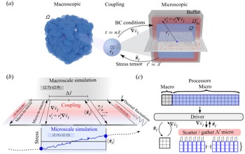
 $\mathcal {N} = \bar {N}$, such that one microscopic simulation is generated per each macroscopic particle. Of course, microscopic simulations contain a large number of microscopic degrees of freedom (e.g. polymers, colloids, droplets) on which the mean average is referred. In general, the total number of degrees of freedom (particles) required to describe a system using LHMM decreases compared with a fully resolved microscopic system when the length scale separation between scales increases (i.e. towards a continuum representation of the fluid), which offers significant advantages from a computational standpoint. In § 2.5, we further discuss those computational aspects. We present the general stages of the coupling in figure 2 and Algorithm 1 in Appendix A. The coupling strategy is accomplished in two alternating stages: (i) macro-to-micro and (ii) micro-to-macro. In the first stage, the velocity gradient at the macroscale is computed and used to prescribe the boundary conditions at the microscale. Microscale simulations are then conducted using (2.10) and (2.11). In the second stage, the ensemble and time average of the stress for each microscopic simulations is computed and passed to the macroscopic particles to solve (2.7) and (2.8). After updating positions and velocities of the macroscale particles, another coupling loop is started
(a) Schematic representation of the fully Lagrangian heterogeneous multiscale method proposed. (b) Algorithm and (c) parallelization.

2.4.1. Macro-to-micro
At the microscale, we use a generalized boundary condition scheme recently proposed (Moreno & Ellero Reference Moreno and Ellero2021) to non-trivial velocity fields (i.e. mixed shear and extensional) in periodic domains. We decompose the microscopic simulation domain in three regions: buffer, boundary condition ( $\varOmega _{bc}'$) and core (
 $\varOmega '$), as shown in figure 2. The properties of the fluid, such as the stress tensor, are evaluated from the core region. In the boundary-condition region, the velocity of the particles is prescribed from a macroscopic velocity field
 ${\boldsymbol {v}}$. The system is further stabilized and periodic boundary conditions are adopted owing to the buffer region. A detailed description of this domain decomposition approach can be found from Moreno & Ellero (Reference Moreno and Ellero2021). To reconstruct the velocity field
 ${\boldsymbol {v}}$ at boundary regions
 $\varOmega _{bc}'$, we use the velocity gradient
 $\boldsymbol {\nabla } {\boldsymbol {v}}_I$ at the macroscale
 $I$th particle position. The macroscopic
 $\boldsymbol {\nabla } {\boldsymbol {v}}_I$ can be approximated using the SDPD interpolation kernel, such that
 \begin{equation} \boldsymbol{\nabla} {\boldsymbol{v}}_I = \sum_J {F}_{IJ} {\boldsymbol{r}}_{IJ} {\boldsymbol{v}}_{IJ}. \end{equation}
This first-order approximation allows us to compute velocity gradients with a minimal computational cost during the macroscopic force calculation stage. In the results section, we validate the use of this approach. Other high-order alternatives to compute  $\boldsymbol {\nabla } {\boldsymbol {v}}_I$ are also possible. However, it would require an additional spatial interpolation step (Zhang & Batra Reference Zhang and Batra2004). Using (2.17), the velocity
 ${\boldsymbol {v}}'_i$ of the microscale particles located at the boundary-condition region is then determined by
 \begin{equation} {\boldsymbol{v}}_i = {\boldsymbol r}_i' \boldsymbol{\nabla} {\boldsymbol{v}}_I, \quad \forall i \in \varOmega_{bc}', \end{equation}
where the macroscopic velocity field is linearly interpolated taking the macroscopic particle centred at the origin of the box (see figure 2). The extent of the microscopic subsystems is given by the characteristic length  $\varOmega '$. In general, we consider that all microscopic subsystems have the same size
 $\varOmega '$, however, different sizes can be used if the specific features of the flow require it.
2.4.2. Micro-to-macro
Given a macroscopic particle  $I$, we determined its stress tensor,
 $\bar {\boldsymbol {\pi }}_I$, from the microscales. Here, we adopt the Irving–Kirkwood (IK) methodology (Yang, Wu & Li Reference Yang, Wu and Li2012) such that the stress is given by
 $\bar {\boldsymbol {\pi }}_I({\boldsymbol x'};t) = \bar {\boldsymbol {\pi }}_I^K ({\boldsymbol x'};t) + \bar {\boldsymbol {\pi }}_I^P ({\boldsymbol x'};t)$, where
 $\bar {\boldsymbol {\pi }}_I^K ({\boldsymbol x'};t)$ and
 $\bar {\boldsymbol {\pi }}_I^P ({\boldsymbol x'};t)$ account for kinetic and potential contributions to the stress tensor, respectively. This potential contribution contains both hydrodynamic and non-hydrodynamic terms. We use the weighting function
 $w_{IK}({\boldsymbol r'},{\boldsymbol x'})$ for the spatial averaging, whereas time averaging is conducted over a range on
 $N_t'$ microscopic time steps. Transient simulations require careful consideration of the desired level of accuracy. Ensemble averaging alone can lead to a high noise-to-signal ratio, producing spurious fluctuations in the macroscopic system. While running replicates of the microscale simulations can improve ensemble measurement, this incurs a significant overhead, making it impractical for use in the LHMM. To accurately estimate the stress, the IK approach requires spatial and temporal averaging. We propose a simple approximation of the measured stress at the end of the microscopic interval using the computed running average of the stress during that interval, which suffices if the stress magnitude does not significantly change during that interval. For a more precise estimation of the transient stress, a denoising stage can be performed at the end of each coupling loop (Zimmerman, Jones & Templeton Reference Zimmerman, Jones and Templeton2010; Zimon, Reese & Emerson Reference Zimon, Reese and Emerson2016). This involves smoothing and interpolating the measured signal within the interval of the microscopic simulation, followed by using the interpolated approximation to calculate the expected stress at the end of the microscale interval. This approach is particularly useful for systems where larger macroscopic time steps are desired or if the measured stress during the macroscopic interval can exhibit an overshoot.
The kinetic part is then given by (Tadmor & Miller Reference Tadmor and Miller2011)
 \begin{equation} \bar{\boldsymbol{\pi}}_I^K ({\boldsymbol x};t) ={-}\frac{1}{N_t'}\sum_{n=1}^{N_t'} \left[ \sum_{i} m_i \, w_{IK}({\boldsymbol r}_i(n)-{\boldsymbol x}){\vartriangle {\boldsymbol{v}}'_i(n)}\otimes {\vartriangle {\boldsymbol{v}}'_i(n)} \right], \end{equation}
where  $\vartriangle {\boldsymbol {v}}'_i(n) = {\boldsymbol {v}}'_i - \langle {\boldsymbol {v}}' ({\boldsymbol r}_i;n) \rangle$ is the relative velocity of the particle
 $i$ at time step
 $n$. In the IK approach, if
 $\varphi _{ij}$ is the magnitude of the force between particles
 $i$ and
 $j$, it is considered that the force term can be expressed in central force decomposition as
 \begin{equation} {\boldsymbol f}_{ij}(n) \otimes {\boldsymbol r}_{ij}(n) = \frac{\varphi_{ij}(n){\boldsymbol r}_{ij}(n)}{r_{ij}(n)} \otimes {\boldsymbol r}_{ij}(n). \end{equation}
With this, the potential part of the stress tensor reads
 \begin{equation} \bar{\boldsymbol{\pi}}_I^P ({\boldsymbol x},t) = \frac{1}{2N_t'}\sum_{n=1}^{N_t'} \left[\sum_{\substack{i,j \\ i\neq j}} {\boldsymbol f}_{ij}(n) \otimes {\boldsymbol r}_{ij}(n) \, \mathcal{B}({\boldsymbol x};{\boldsymbol r}_i(n),{\boldsymbol r}_j(n)) \right] ,\end{equation}
where  $\mathcal {B}({\boldsymbol x};{\boldsymbol r}_i(n),{\boldsymbol r}_j(n))$ is a bond function given by
 $\mathcal {B}({\boldsymbol x; u,v}) = \int _{s=0}^1 w_{IK} ((1-s){\boldsymbol u}+s {\boldsymbol v}-\boldsymbol {x} ) \,\textrm {d} s$. The bond function is the integrated weight of the bond for a weighting function centred at
 $\boldsymbol x$. If the weighting function
 $w_{IK}(\kern1pt \boldsymbol{y}-{\boldsymbol x})$ is taken as constant within a domain
 $\varOmega _a$ and zero elsewhere,
 $w_{IK} = 1/\textrm {Vol}(\varOmega _a)$ if
 ${\boldsymbol y} \in \varOmega _a$. If additionally, the bond function
 $\mathcal {B}$ is calculated only with bonds fully contained in
 $\varOmega _a$, we would have
 $\mathcal {B}({\boldsymbol x};{\boldsymbol r}_i,{\boldsymbol r}_j) = 1/\textrm {Vol}(\varOmega _a)$ for
 $i-j \in \varOmega _a$. For more detailed descriptions and extended validation benchmarks, we refer the reader to the work of Moreno & Ellero (Reference Moreno and Ellero2021).
2.4.3. Time stepping
A critical aspect of heterogeneous multiscale methods is the time-stepping approach used to send information between scales (Ee, Ren & Vanden-Eijnden Reference Ee, Ren and Vanden-Eijnden2009; Lockerby et al. Reference Lockerby, Duque-Daza, Borg and Reese2013). From macroscales, we consider the time step is given by  $\Delta {t}$, whereas the overall time scale
 $\lambda _{MM}$ of the system investigated is related to the operative conditions, such as the shear rate,
 $\dot {\gamma }$. Thus, macroscopic scales define the extent of the overall simulations, requiring a minimum of
 $m$ steps (
 $\lambda _{MM} = m\Delta {t}$). The time-stepping approach depends on the time-scale separation between macro- and microsystems. If we denote the characteristic relaxation time for each scale as
 $\lambda$, systems with large time scale separation satisfy
 ${\lambda }' \ll {\lambda }$, whereas for highly coupled scales,
 ${\lambda }' \approx {\lambda }$. From microscales, the time step
 $\Delta {t}'$ sets the condition to accurately resolve the stress evolution of the system. The relaxation of the microscales requires a minimal number of time steps
 $n$, such that
 ${\lambda }' = n \Delta {t}'$. In practice, microscopic simulations would use
 $n$ large enough (
 ${\lambda }' < n \Delta {t}'$) to ensure the proper stabilization of the system and to reduce the noise-to-signal ratio.
In multiscale methods, the relaxation time of the macro- and microsystems determines the ratio  $\Delta {t}/ \Delta {t}'$. As the limit condition for the highest temporal resolution, we can consider the case of
 $\Delta {t}/ \Delta {t}' = 1$. However, in practice, this would not correspond to a temporal multiscale method, but a fully microscopic description of the system. In those cases, the gain in performance for using HMM comes only from the spatial upscaling of the stress. Existent LL schemes (Yasuda & Yamamoto Reference Yasuda and Yamamoto2014; Sato & Taniguchi Reference Sato and Taniguchi2017; Sato et al. Reference Sato, Harada and Taniguchi2019) that use time steps in the same order for macro- and microsolvers are limited to problems with microscale temporal resolutions. Otherwise, in the case of stochastic microscale simulations (Morii & Kawakatsu Reference Morii and Kawakatsu2021), equilibration of the microscales is assumed through mean-field approximations. Due to these practical restrictions, different time-stepping approaches have been recently investigated (Ee et al. Reference Ee, Ren and Vanden-Eijnden2009; Lockerby et al. Reference Lockerby, Duque-Daza, Borg and Reese2013) to increase the temporal gain in HMMs and reach macroscopic time scales. Depending on the order of magnitude of
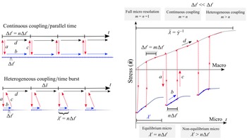
 $\Delta {t}/ \Delta {t}'$, different time-stepping schemes can be used. In figure 3, we illustrate the basic sequence of time stepping: (a) scattering
 $\boldsymbol {\nabla } {\boldsymbol {v}}_I$ on individual microscopic solvers; (b) solving microscales under arbitrary BC; (c) gathering
 $\bar {\boldsymbol {\pi }}_I$ for macroscales; and (d) solving macroscales. The simplest time-stepping, typically referred as continuous coupling between scales (see figure 3), considers that microsolvers are evolved during
 $n\Delta {t}'$, whereas the time integration at macroscale occurs at
 $\Delta {t} = n\Delta {t}'$. An alternative to achieve both spatial and temporal gain when using our LL schemes is the heterogeneous-coupling time stepping (Lockerby et al. Reference Lockerby, Duque-Daza, Borg and Reese2013) (as known as time burst), as presented in figure 3. In time-burst approaches, the macroscales are evolved using
 $\Delta {t} = m \Delta {t}'$, where
 $m\gg n$. Therefore, microscale behaviour is extrapolated over larger periods. Compared with continuous coupling, the overall gain of heterogeneous time stepping is given by the ratio
 $m/n$. In general, for highly coupled scales (
 ${\lambda }' \approx {\lambda }$), we would require
 $m \sim n$ to reach the continuous coupling. The EE and EL schemes with time-burst time stepping have been adopted for systems with large enough time scale separation (
 ${\lambda }' \ll {\lambda }$). However, due to the incompatibility of a simple Eulerian description to capture memory effects, this approximation of constant microscopic stresses over a larger macroscopic time exhibit larger deviations as the microscale relaxation time increases. These limitations can be significantly relieved using LL schemes (Ee et al. Reference Ee, Ren and Vanden-Eijnden2009). Here, depending on the type of system and scale separation, we used both continuous and heterogeneous coupling in time.
Time-stepping approaches and information passing between scales. In LL schemes, it is in principle possible to pass information from micro solvers before reaching full equilibration, since the historically dependent stress is naturally tracked in the Lagrangian framework.

The Lagrangian nature of the proposed framework represents a critical ingredient to perform the multiscale coupling with SDPD. Flow history is by default accessible to every element of fluid (SPH particle), which carries its microstructure (in a Lagrangian sense). As a consequence, the initial conditions (SDPD positions/velocities) at every macroscopic time step can be taken as those at the end of the previous time step, regardless of whether the microstructure has relaxed or not within it. This idea allows us to apply HMM directly to the flow of complex fluids by running SDPD simulations in parallel (one for each SPH particle) undergoing inhomogeneous and possibly unsteady velocity gradients obtained from the macroscopic SPH calculation. As discussed by Bertevas, Fan & Tanner (Reference Bertevas, Fan and Tanner2010), accurate IK estimates in mesoscopic calculations require typically periodic representative elementary volumes (RVEs) three to ten times larger in linear size than the suspended solid particles, and therefore we expect a significant computational gain when applying this procedure to SPH fluid volumes much larger than the RVE.
2.5. The LHMM implementation
Since each macroscopic particle is equipped with its microscale solver, the overall cost of the HMM simulations increases compared with constitutive-equations-based approaches. However, the expected cost is significantly reduced for fluids that require to be solved with a resolution at the microscopic scale (polymer coil or colloid scale for example). The LL schemes offer parallelization advantages, allowing each macroparticle to compute its stress independently. Here, we implement the LHMM using a c++ driver, coupled with multiple parallel instances of LAMMPS (Plimpton Reference Plimpton1995) to solve both macro- and microscales. In figure 2(c), we illustrate the parallelization approach used. An important feature of the current implementation is that both macro- and microscales can be fully parallelized separately. This has significant advantages compared with fully microscopically resolved systems. In those, the computational cost does not scale linearly as the size of the macroscopic domain reaches continuum scales.
Since both scales are solved using SDPD, we can estimate the relative cost of solving a given system in terms of the total number of discretizing particles used or degrees of freedom (DOFs). Considering a macroscopic system of size  $\bar {L}$ being fully microscopically resolved with interparticle distance
 $\textrm {d}\kern0.7pt x'$, the total number of DOFs is then given by
 $N_{full} = (\bar {L}/\textrm {d}\kern0.7pt x')^D$, where
 $D$ is the dimension of the system. This system in an LHMM discretization requires
 $N_{LHMM} = \bar {N}N'$ total particles, where
 $\bar {N} = (\bar {L}/\textrm {d}\,{x})^D$ and
 $N' = (\varOmega '/\textrm {d}\kern0.7pt x')^D$, with
 $\varOmega '$ being the size of the microscopic domain sampled. Additionally, if we define the spatial and temporal gain of the LHMM method as
 $G_s = \bar {h}/\varOmega '$ and
 $G_t = \Delta {t}/\Delta {t}'$, respectively, the total number of DOFs for LHMM can be expressed as
 \begin{equation} N_{LHMM} = N_{full} \left(\frac{\varOmega'}{\text{d}\,{x}}\right)^D = N_{full} \frac{\kappa}{G_s}, \end{equation}
where the ratio  ${\varOmega '}/{\textrm {d}\,{x}}$ is inversely proportional to the spatial gain
 $G_s$ achieved by the LHMM, since at the macroscale,
 $\bar {h} = \kappa \,\textrm {d}\,{x}$. The value of
 $\kappa$ is typically determined by the required number of neighbour points for the kernel interpolation and is related to the accuracy of the method (Ellero & Adams Reference Ellero and Adams2011). Herein, we use
 $\kappa =4$ (Bian et al. Reference Bian, Litvinov, Qian, Ellero and Adams2012) (for both macro- and microscales). From (2.22), we can readily identify that, compared with a fully resolved system, the LHMM entails a reduction in DOFs required for systems with
 $G_s>4$. In general, the goal of HMM is to model systems with spatial gains orders of magnitude larger to tackle continuum scale problems with microscopic detailed effects.
Another computational gain associated with the LHMM is the flexibility of using larger time steps compared with a fully resolved system. The Courant–Friedrichs–Lewy (CFL) condition determines the stability criterium for the minimum integration time step for microscales,  $\Delta {t}' = \textrm {d}\kern0.7pt x'/c$, where
 $c$ is the artificial speed of sound. As discussed in the previous section, for a target macroscopic time scale
 $\lambda _{MM}$, the total number of times steps required is then
 $n_{full} = \lambda _{MM}/\Delta {t}' = (c\lambda _{MM})/\textrm {d}\kern0.7pt x'$. Thus, for instance, to model a system of the order of seconds with a nanoscopic resolution would typically require
 $n_{full} \propto 10^{12}$ time steps. In LHMM, the CFL condition at the macroscale allows the use of
 $\Delta {t} = \textrm {d}\,{x}/c \propto G_s\Delta {t}'$, which scales with the spatial gain, so it is, in principle, feasible to integrate macroscale equations over significantly larger time steps. It is worth noting that a slightly smaller macroscopic time steps may be preferred to comply with the characteristic microscopic relaxation time, as discussed in the previous section. In HMM, the temporal gain is, in general, limited by the capability of the method to accurately keep track of the historically dependent stress. This aspect is an important feature of the proposed fully Lagrangian scheme, allowing the use of larger macroscopic time steps, compared with Eulerian–Lagrangian settings.
3. Macro and micro descriptions
We conduct a series of different benchmark tests for a simple Newtonian fluid to validate the consistency and stability of the proposed multiscale method. We consider a macroscale system under reverse Poiseuille flow (Fedosov, Karniadakis & Caswell Reference Fedosov, Karniadakis and Caswell2010) (RPF) in a domain of size  $L_y \times L_x$ and evaluate the effect of the stabilizing parameter
 $\epsilon$ on the range
 $[0\unicode{x2013} 1]$. In RPF schemes, an external force,
 $F_{ext}$, is applied in the upper half of the simulation box, whereas
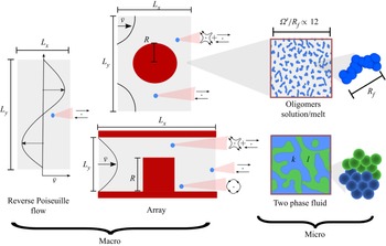
 $-F_{ext}$ is imposed in the lower half. Additionally, we evaluate the proposed LHMM framework on other geometries that induce different local flow types (i.e. shear, extension and mixed flow) corresponding to a flow in circular- and square-contraction arrays. The use of arbitrary BC (Moreno & Ellero Reference Moreno and Ellero2021) at the microscales allows us to account for different spatial flow configurations. In figure 4, we summarize the type of flow configurations investigated. For circular arrays, the size of the channel was
 $L_y=16\bar {h}$ and
 $L_x=20\bar {h}$, whereas the size of the contraction is
 $R=4\bar {h}$. The number of particles used for microscopic simulations ranged from two to four thousand. At the walls, we adopt the methodology used by Bian et al. (Reference Bian, Litvinov, Qian, Ellero and Adams2012), such that the velocity of the wall particles used to compute the viscous forces is extrapolated to enforce non-slip boundary conditions,
 ${\boldsymbol {v}}=0$, at the fluid–wall interface.
Sketch of macro- and microscopic systems investigated. At the macroscale, reverse Poiseuille flow and flow in arrays (cylindrical and square) are constructed. For microscales, in addition to the standard Newtonian fluid, complex fluids are modelled as oligomeric solutions and melts, and two immiscible fluids  $k$ and
 $l$, undergoing microphase separation.

To illustrate the flexibility of the proposed LHMM framework at the microscales, we model various physical problems. We adopt different generic SDPD models for polymeric and multiphase systems. We must note that these complex fluids are used here only to showcase our multiscale methodology, thus, a systematic parametric analysis of the specific systems is out of the scope of this work and will be addressed in future publications. We must remark that in the current LHHM approach, we consider that the compositions (i.e. polymer or phases) remain constant during the whole macro–micro simulation. Therefore, effects such as shear stress-induced migration between the macroscopic particles is not accounted for. Further generalization of the LHMM to account for those effects can be attained by including additional evolution equations for compositional fields (Ellero et al. Reference Ellero, Español and Flekkoy2003) discretized at the macroscopic level, such that microscopic simulations can be generated on the fly accordingly. Stress-driven transport could be also generalized in our LHMM to include the stress-gradient-induced polymer migration models (Zhu et al. Reference Zhu, Rezvantalab, Hajizadeh, Wang and Larson2016; Hajizadeh & Larson Reference Hajizadeh and Larson2017).
3.1. Oligomer melts
We model non-Newtonian fluids by constructing melts of oligomers of  $N_s=8$ and
 $N_s=16$ connected SDPD particles. We use the finitely extensible nonlinear elastic (FENE) potential of the form
 $U_{fene} = -1/2 k_s r_s^2 \textrm {ln} [1-(r/r_s)^2]$, where
 $k_s$ and
 $r_s$ are the bond energy constant and maximum distance, respectively. In our simulations, we fix
 $k_s = 23k_BT/r_s^2$ and
 $r_s=1.5\textrm {d}\kern0.7pt x'$. We characterize the oligomers in the system through its end-to-end vector
 $\boldsymbol {R}_f$ to determine the mean end-to-end distance
 $\langle R_f \rangle ^2 = \langle |\boldsymbol {R}_f|\rangle ^2$. The equilibrium end-to-end radius,
 $R_f$, measured from simulations under no flow condition is
 $R_f = 0.3\pm 0.02$ at
 $k_BT =1$. For simulations conducted at
 $k_BT=0.1$, the measured
 $R_f=0.11\pm 0.01$. Given the size of the microdomain and oligomers, the microscales are being sampled on size ratios of approximately
 $10 < \varOmega '/R_f \sim <13$. Polymeric systems constructed in similar fashion in SDPD (Simavilla & Ellero Reference Simavilla and Ellero2022) have shown that the polymer relaxation times
 $\lambda _p$ agreed with the Zimm model. Herein, we identify relaxation times for
 $N_s = 8$ of the order of
 $\lambda _p \approx 6 t_{SDPD}$ and for
 $N_s=16$ of the order of
 $\lambda _p \approx 9 t_{SDPD}$. The Weissenberg numbers (
 $Wi=\dot {\gamma }\lambda _p$) investigated on the different examples, full micro- and multiscale, ranged from
 $0.3$ to
 $100$.
3.2. Two-phase flow
We also constructed microscale systems constituted by two immiscible phases  $l$ and
 $k$. The composition of each phase is denoted as
 $\kappa _p$, for
 $p=k,l$, such that the binary mixture satisfies
 $\kappa _l + \kappa _k =1$. We adopt the SDPD scheme proposed by Lei et al. (Reference Lei, Baker, Wu, Schenter, Mundy and Tartakovsky2016) for multiphase flows. In this scheme, the momentum equation at microscale (2.11) incorporates an additional pairwise term
 $F^{int}$ that accounts for interfacial forces between the two phases
 $k$ and
 $l$, such that
 \begin{equation} F_{ij}^{int} ={-}s_{ij} \phi(r_{ij}) \frac{{\boldsymbol r}_{ij}}{r_{ij}}, \end{equation}
where
 \begin{equation} s_{ij} = \begin{cases} s_{kl} & \text{if} \ {\boldsymbol r}_i \in \varOmega_k \text{ and } {\boldsymbol r}_j \in \varOmega_l,\\ s_{kk} & \text{if} \ {\boldsymbol r}_i \in \varOmega_k \text{ and } {\boldsymbol r}_j \in \varOmega_k,\\ s_{ll} & \text{if} \ {\boldsymbol r}_i \in \varOmega_l \text{ and } {\boldsymbol r}_j \in \varOmega_l, \\ \end{cases} \end{equation}
and  $\phi (r_{ij})$ is a shape factor given by
 \begin{equation} \phi = r_{ij} [{-}G{\rm e}^{-({r_{ij}^2}/{2r_a^2})} + {\rm e}^{-({r_{ij}^2}/{2r_b^2})} ], \end{equation}
where  $G=2^{D+1}$, with
 $D$ being the dimension. The range for repulsive and attractive interactions are defined as
 $2r_a = r_b = \rho _n^{-1/D}$, such that a relative uniform particle distribution is obtained for a given interfacial tension
 $\sigma$. The interaction parameters satisfy
 $s_{kk} = s_{ll} = 10^3s_{kl}$, and the magnitude can be obtained from the surface tension and particle density of the system as
 \begin{equation} s_{ii} = \frac{1}{2(1-10^{{-}3})}\rho_n^{{-}2} \frac{\sigma}{[4-D]^{{-}1}([4-D]\pi)^{1/[4-D]} ({-}Gr_a^{D+3}+r_b^{D+3})}. \end{equation}
Here, we model the multiphase systems considering a viscosity ratio between both phases  $\eta _k/\eta _l = 1$ and interfacial tension
 $\sigma = 0.5$. The characteristic time,
 $\lambda _{ps}$, for total phase separation of a phase
 $k$ with concentrations of
 $0.2$ and
 $0.5$ (starting from a homogeneous mixture) were identified as
 $\sim 140 t_{SDPD}$ and
 $\sim 40 t_{SDPD}$, respectively. In general, the size (
 $4h < \varOmega ' <10h$) of microscale systems investigated and shear rates used lead to capillary numbers
 $Ca = (\eta \dot {\gamma } \varOmega ')/(2\sigma )>10$ that are typical for highly deformable and breakable droplets of the suspending phase (Kapiamba Reference Kapiamba2022). It has been shown experimentally that at low
 $Ca$ numbers, the steady-state morphology of multiphase systems can be described as a single value function of the flow. However, when microstructural properties are determined by the balance between break-up and coalescence of the phases, the morphology can be controlled by the initial conditions of the system, leading to more than one steady-state morphology (Minale, Moldenaers & Mewis Reference Minale, Moldenaers and Mewis1997).
4. Results and discussion
The proper estimation of the velocity gradient at macroscales as well as the correct measurement of the stress tensor from microsystems are key components of the proposed LHMM. Therefore, we verify that numerical errors associated with particle resolution at each scale are negligible and that the arbitrary boundary conditions used for microscales do not introduce spurious artefacts on the stress for complex systems. In Appendices C–E, we present a detailed validation of both scales discretizations independently.
4.1. Fully microscopically resolved simulations
To validate the accuracy of the proposed LHMM, we conduct RPF simulations of a fully resolved (micro) Newtonian fluid and oligomeric melts using simulation domains with length scales of the order of  $\bar {L} \propto 10^{2}\,\textrm {d}\kern0.7pt x'$ to
 $10^3\,\textrm {d}\kern0.7pt x'$. For oligomeric melts, we can refer to the domain size in terms of the end-to-end distance of the coils. As a consequence, for oligomers with
 $N_s = 16$ and
 $R_f \approx 1.5\,\textrm {d}\kern0.7pt x'$, the fully resolved domains correspond to lengths of the order of
 $200R_f$ to
 $800R_f$. These fully resolved systems require between
 $10^{3}$ and
 $10^6$ microscopic particles or DOFs. We must remark that macroscopic domains using fully resolved microscopic scales can be typically of the order of
 $\bar {L} > 10^{8}\,\textrm {d}\kern0.7pt x'$, thus requiring DOF
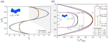
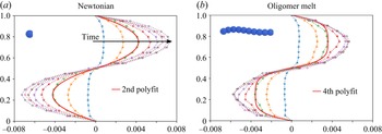
 $>10^{9}$. The computational cost to simulate such large systems quickly becomes prohibitive, even for efficiently parallelizable codes. The domain size used herein provides a baseline to evaluate the accuracy of the proposed LHMM framework and is already large enough to evidence the high computational demand for this type of system. In figure 5(a), we compare the velocity profiles for a fully resolved Newtonian and an oligomeric melt. Under the same forcing, the non-Newtonian behaviour of the oligomeric melt is evidenced by a reduced velocity (larger viscosity) and flattened profile. Solid lines correspond to the quadratic and fourth-order fitting of the velocities for the Newtonian and melt, respectively. In figure 5(b), we present the velocity profile of the upper-side RPF velocity profile obtained for three different domain sizes with fixed
 $\boldsymbol {\nabla } {\boldsymbol {v}}_{xy}|_{max}$. As the domain size increases, the effective velocities of the system change. However, the non-Newtonian profile is consistently preserved.
(a) Fully microscopically resolved RPF for Newtonian and non-Newtonian fluid. Non-Newtonian fluids are modelled oligomers with  $N_s=16$ particles per chain. (b) Closeup of the upper part of an RPF for different domain sizes evidencing a characteristic non-Newtonian profile. We indicate the total number of degrees of freedom (particles) required in those simulations along with the box and oligomer size ratio, for each case. Larger domains will readily require DOF
 $> 1\times 10^6$.

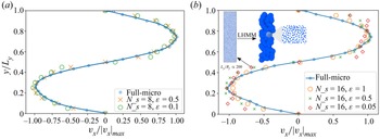
In figure 6, we compare the corresponding velocity profiles obtained from fully resolved microscopic solutions and the proposed LHMM for two oligomeric systems ( $N_s=8$ and
 $N_s=16$, with
 $\bar {L}=64$). The LHMM results correspond to simulations with
 $\textrm {d}\,{x}=3.2$ and
 $\textrm {d}\kern0.7pt x'=0.2$. Considering a kernel size
 $\bar {h} =4\,\textrm {d}\,{x}$ and a microscopic domain
 $\varOmega ' = 20\,\textrm {d}\kern0.7pt x'$, the spatial gain for these tests is
 $G_s=3.2$. We evaluate the influence of the stabilizing parameter
 $\epsilon$. In general, we observe that when hydrodynamic contributions are only accounted for from macro simulations,
 $\epsilon \approx 1$, the effective viscosity of the systems increases leading to slightly smaller velocities for LHMM. Such an effect is reduced as
 $\epsilon$ diminishes. When hydrodynamic,
 $\epsilon \approx 0$, the obtained velocity exhibit instabilities that are likely related to the macroscopic particle resolution. Since the stresses are only accounted for from microsimulations when
 $\epsilon = 0$, the viscous interactions between macroscopic particles can experience numerical fluctuations due to the stress calculation from microscopic transient simulations. However, we must note that even for
 $\epsilon = 0$, the order of magnitude of the viscous stresses is closely related to the fully microscopic results. The LHMM with
 $\epsilon \approx 0$ reproduces up to a good approximation the characteristic behaviour of the oligomeric system. Overall, we identify that stabilization parameters
 $\epsilon >0.1$ provide a reasonable stabilization of the stresses.
The RPF velocity profiles for two different oligomeric melts with  $N_s=8$ and
 $N_s=16$ using different values of the stabilizing parameter
 $\epsilon$. Overall, the LHMM schemes capture up to a good approximation the effect of microscopic oligomer chains in the flow. For
 $N_s=16$, relatively larger deviations are observed as
 $\epsilon \approx 0$. This is likely because of the noise-to-signal ratio of the computed stress for larger chains. Further improvement can be achieved by increasing the sampling volume at the microscales.

4.2. The LHMM for complex fluids
Now, we continue evaluating the proposed LHMM on a macroscopic domain with significantly larger spatio/temporal gain, solving the microscales using the SDPD equations (2.10)–(2.12). For macroscopic simulations, we consider a fluid with properties  $\rho =1000\,\textrm {kg}\,\textrm {m}^{-3}$,
 $\bar {\eta }=1\times 10^{-3}\,\textrm {Pa}\,\textrm {s}$,
 $c=0.1\,\textrm {m}\,\textrm {s}^{-1}$,
 $\bar {p}_b=1\,\textrm {Pa}$. The macroscopic time and length scales are defined in terms of
 $\Delta \bar {t}=0.0002\,\textrm {s}$,
 $\textrm {d}\,{x} = 5\times 10^{-4}\,\textrm {m}$ and
 $\bar {h}=0.002\,\textrm {m}$, respectively (see table 1). For microscales, we adopt a resolution
 $\textrm {d}\kern0.7pt x' = 2.5\times 10^{-10}\,\textrm {m}$, such that the size of the microscopic kernel is
 ${h}'=4\,\textrm {d}\kern0.7pt x'=1\times 10^{-10}\,\textrm {m}$ and
 $\varOmega ' = 20\,\textrm {d}\kern0.7pt x'$. Therefore, these LHMM simulations correspond to spatial gains
 $G_s \approx 4\times 10^{6}$. From (2.22), we can observe that it implies a reduction in the required DOF of
 $\propto 10^{6}$, compared with the fully microscopically resolved system.
Macroscopic fluid and system parameters.

To streamline the construction of the different microscopic systems and presentation of the results, we conduct microscopic simulations using reduced units ( $X'=X_{physical}'/X_{ref}'$). We introduce a reference length (
 $h_{ref}'= 1.25\times 10^{-9}\,\textrm {m}$), mass (
 $m_{ref}'= 1.56\times 10^{-15}\,\textrm {kg}$) and time (
 $t_{ref}'= 0.0125\,\textrm {s}$) scales (see table 2). Henceforth, unless otherwise stated, the reduced fluid properties of the microscopic simulations are consistently given by
 $\rho '=1.0$,
 ${\eta }'=10$. The particles are initially localized in a square grid with an interparticle distance
 $\textrm {d}\kern0.7pt x'= 0.2$. Additionally, for microscopic simulations, we use
 $c'=40$ and
 ${p}_b'=50$. The time step is chosen to satisfy the incompressibility of the system and ensure numerical stability. We choose the smaller time scale between the CFL condition,
 $\Delta t' = h'/(4({\boldsymbol {v}} +c))$, and the viscous time scales,
 $\Delta t' = h'^2/(8\eta '\rho ')$. Thus, we use
 $\Delta {t}'=0.0001$ to ensure lower density fluctuations. At microscales, we account for thermal fluctuation, thus the energy scale is determined by
 $k_BT=1.0$. Following the results reported by Moreno & Ellero (Reference Moreno and Ellero2021), we construct microscale simulations suitable for arbitrary boundary conditions with a core size between
 $\varOmega ' = 15\,\textrm {d}\kern0.7pt x'$ and
 $\varOmega ' = 20\,\textrm {d}\kern0.7pt x'$ (i.e. the size of the sample to determine the stresses), whereas the sizes of the boundary condition and buffer regions are
 $5\,\textrm {d}\kern0.7pt x'$ and
 $5\,\textrm {d}\kern0.7pt x'$, respectively.
Microscopic fluid and system parameters.

In Appendix F (see figure 17), we compile the steady-state velocity profiles obtained for a Newtonian flow, using the stress tensor computed directly from microscopic subsystems ((2.19) and (2.21)), for various  $\epsilon$. Consistently, in figure 17, we can observe that microscale simulations can recover the macroscopic stress tensor, leading to the proper modelling of the flow. This represents an evidence of the robustness of SDPD to capture the ideal solvent contributions across scales. For comparison, we have included the velocity profile obtained for a system without microscale contributions.
4.2.1. Oligomeric melt
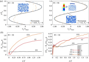
In figure 7, we show the steady-state results for an RPF flow configuration of oligomeric melts at different shear rates. We can observe the characteristic shear-thinning effect induced by the alignment of the chains in the flow. Overall, the magnitude of the stabilization parameter did not induce any effect on the rheology of the fluid, evidencing a proper description of the fluid from both macro- and microscales separately. In addition to the steady-state solution, we were able to capture the characteristic deviations in the temporal evolution for the oligomer melt (see Appendix G). For the Newtonian fluid, the velocity profile is consistently reproduced by a quadratic fitting, whereas the microscopic effects of the oligomer chains lead to a fourth-order velocity profile in the non-Newtonian fluid.
The RPF for non-Newtonian fluid, using oligomers with  $N_s=8$. (a) Comparison between Newtonian and non-Newtonian for two values of
 $\epsilon = 0.01$ and
 $\epsilon = 0.2$. The magnitude of the stabilization parameter does not affect the rheology of the fluid, evidencing a proper description of the fluid from both macro- and microscales separately. Shear-thinning effect of oligomer melts at different shear rates. The value of
 $\epsilon =0.01$ is used for low shear rates. As the shear rate increases, the value of
 $\epsilon =0.2$ is used to ensure stability of the measured stress. (b) Variation of the stress and first normal stress differences for three different macroscopic particles (i)–(iii). The initial position of the particles is highlighted on the right, (i) in red at
 $y/L = 0.55$, (ii) in black at
 $y/L = 0.35$ and (iii) in orange at
 $y/L = 0.1$. Microscales are constituted by oligomers with
 $N_s=8$. The characteristic normal stress differences in the fluid increase due to the microscopic response of the chains.

In addition to the differences in the velocity profile for oligomeric melts, another relevant characteristic that can be analysed for this non-Newtonian fluid is the evolution of their stresses. In figure 7(b), we present the variation of the shear stress and first normal stress difference for three macroscopic particles (highlighted in red, black and orange) at  $Wi=30$, for oligomer melts with
 $N_s=8$. The particles are initially localized at positions across the domain such that they experienced different magnitudes of stress. As described in figure 7, a shear-thinning behaviour can be evidenced in the magnitude of
 $\bar {{\rm \pi} }_{xy}$ when the shear rate increases. Additionally, the emergence of first normal stress differences is observed for the macroscopic particles due to the microscopic response of the chains.
4.2.2. Multiphase flow
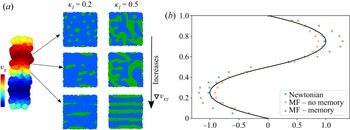
Using the same RPF setting at the macroscales, we can easily investigate other physical systems with different microscopic features. In figure 8, we compile the results obtained for multiphase flows using two phases  $l$ and
 $k$, with compositions
 $\kappa _l=0.1$ and
 $\kappa _l=0.5$. In these simulations, the two phases are initially mixed and the phase separation takes places concurrently with the imposition of the flow. As a result, the macroscopic shear affects the morphology of the microstructure formed, leading to a different response of the mixture. The characteristic size of the microstructure depends on the phase composition. Low concentrations of
 $l$ phase favour spherical to elongated droplet transitions, whereas at intermediate concentrations, the increase in the shear rate induces transitions of the microstructure from disordered spinodal to lamella-like structures.
(a) Typical velocity profile for RPF coupled with multiphase flow at microscale, using two different compositions of the phase  $l$,
 $\kappa _l=0.2$ and
 $\kappa _l=0.5$. (b) Comparison of the steady-state velocity profile obtained for a Newtonian fluid and two schemes of LHMM simulations. The phase separation at microscales results in a shear-thinning behaviour of the macroscopic flow. For comparison, we include the steady profile for a system without historical tracking of the microscale. In that situation, the formation of microstructures with larger relaxation times is never reached, and the fluid behaves similar to the Newtonian fluid.

In figure 8, we also compare the steady-state velocity profile obtained for a Newtonian fluid and the multiphase case with  $\kappa _l=0.5$. For comparison, we have included the profile for a multiphase system where the microstructure at the beginning of each macroscopic time step is reinitialize as fully mixed. This assumption is consistent with microstructural evolution reaching its equilibrium condition on time scales much smaller than the macroscopic time step. However, for these types of systems, it will imply that the historical evolution of the microstructure is neglected. In general, we observe that the microphase separation results in a shear-thinning behaviour for the multiphase systems modelled. Remarkably, we can observe that the thinning behaviour roots in the proper history tracking of the microstructure. In systems without memory, the formation of microstructures with larger relaxation times is never reached, and the fluid resembles the Newtonian behaviour of their individual phases.
4.3. Flow through complex geometry
Now, we evaluate the proposed LHMM framework on geometries that induces different local flow types (i.e. shear, extension and mixed flow) for both oligomer melts and multiphase flows. For these large macroscopic domains, a direct validation with the fully microscopically resolved systems is computationally taxing. Therefore, for complex geometries, we first validated the simple Newtonian fluid in the LHMM scheme, with respect to the corresponding Newtonian fluid as modelled from a macroscopic simulation (using only SPH simulations) (see Appendix F, figure 18). Overall, we identify that the LHMM consistently captures the behaviour of the ideal fluid, on the range of parameters evaluated.
4.3.1. Oligomeric melt
In figure 9, we present the steady velocity and stresses for an oligomeric melt ( $N_s=16$), passing a cylindrical array at
 $Wi=0.4$. For the cylindrical contraction, we use a domain of size
 $19\,\textrm {d}\,{x} \times 27\,\textrm {d}\,{x}$ and the radius of the cylinder
 $R=6\,\textrm {d}\,{x}$. The size of the macroscopic kernel
 $4\textrm {d}\,{x}= 64$ and the microscopic domain size
 $\varOmega '=8$ are defined such that the overall spatial gain of these simulations is
 $G_s=8$ with an aspect ratio between the cylinder
 $R$ and the coil size
 $R_f$ of nearly
 $300$ times. The flow at the macroscale is induced by an external forcing
 $f_{ext}=0.58$ acting on the fluid particles. Fully microscopically resolved simulations of these systems would require over
 $10^7$ particles for a two-dimensional system, in contrast to the
 $10^6$ particles used for LHMM. Figure 9(a) compares the velocity and stress contours between a Newtonian and oligomeric melt. In general, we identify alterations in the steady profiles arising from the enhanced viscosity of the oligomer melts. The characteristic shear thinning response of the melt (as discussed in previous sections) to the spatially changing velocity gradient induces a modest but evident break in symmetry for both velocity and stress. In figure 9(b), we plot the profiles along the vertical line at the entrance of the domain. The higher viscosity of the oligomeric melts is consistent with the typical flattened velocity profile observed and the larger stress. The stress profiles along a vertical and horizontal line are also presented in figure 9(c,d) to illustrate the larger stress contribution due to the oligomeric chains and the change in the generated stress along the channel.
Comparison of the velocity and hydrodynamic stresses contours (a) between a Newtonian and oligomeric melt around a cylinder (at  $Wi=0.4$). In a domain of size
 $19\,\textrm {d}\,{x} \times 27\,\textrm {d}\,{x}$ with a radius of cylinder of
 $R=6\,\textrm {d}\,{x}$. (b) Comparison of the velocity profile along a vertical line at the entrance of the channel. Microscopic features of the chains at the microscales induce the deviation of the Newtonian behaviour leading flattened velocity profile. (c,d) Stress variation along (a,c) vertical and (a,d) horizontal slices are presented to compare the response of both fluids.

4.3.2. Multiphase flow
The capabilities of the method to track history-dependent effects are further shown using multiphase flows in a square cavity array. In figure 10, we include the velocity and stress profile for a Newtonian and a biphasic fluid, averaged over the same macroscopic time span. For the biphasic fluid, the microscale simulations are initialized as homogeneously mixed phases, with  $\kappa _k=0.5$, that undergo microphase separation as they flow through the channel. As a result, multiphase flows are characterized by the emergence of microstructures that can evolve with the simulation, therefore carrying historical information during their transport across the channel. The formation of such microstructures is additionally affected by the spatially variable velocity gradient experienced by each macroscopic particle. Consistently, as the particles move within the domain, the state of the microstructure determines their stress response, affecting the macroscopic flow. In figure 10(a), we can observe that the Newtonian fluid has reached a nearly symmetric steady condition for both velocity and stresses. However, the multiphase fluid exhibit a significantly different flow behaviour and stress distribution. Further estimation of the root-mean-squared (r.m.s.) velocity and stresses fluctuation allows us to elucidate that the temporal stability of the velocity and stress are responsible for the observed flow patterns. Figure 10(b) evidences the persistent fluctuations on multiphasic systems, due to the continuous evolution of the microstructure. Different from simple Newtonian fluids, multiphase flows are likely to require larger simulation times to reach a steady-state condition (in the statistical sense). In Appendix H, we present the evolution of the velocity and stress (and r.m.s. fluctuations) for multiphase flow at different time steps, evidencing that multiphasic systems have not yet reached a steady condition. We must highlight that when comparing the stress evolution between Newtonian and multiphase flows, the latter is characterized by larger relaxation times (
 $\lambda _{ps}$) that typically exceed a single microscopic simulation. The LHMM used herein allows us to naturally account for such large relaxation times while keeping the modelling of microscopic simulations computationally feasible.
Comparison of the velocity and stress  $\bar {{\rm \pi} } _{xy}$ on a square-contraction array for Newtonian and multiphase flows. (a) Steady-state velocity and stress contours and (b) root-mean-squared velocity and stress fluctuations.

It is important to note that depending on the characteristic size  $r_{micro}$ of the microstructure, the size of the microscopic domain must be large enough for the microstructure to be commensurate, this is
 $\varOmega '> r_{micro}$. Since certain physical systems can exhibit microstructures constantly varying in size (e.g. continuously growing aggregates), the definition of
 $\varOmega '$ poses some important challenges, requiring a systematic analysis of the specific physical phenomena investigated. However, these aspects related to varying microstructural size are out of the scope of the present work and will be addressed in future publications. Here, we have focused on showcasing the capabilities and flexibility of the proposed approach.
5. Conclusions and future work
Herein, we proposed a fully Lagrangian heterogeneous multiscale methodology (LHMM), suitable to model complex fluids across large spatial/temporal scales. This methodology offers the advantage of capturing microscopic effects at the macroscopic length scales, with a lower cost than solving the full microscale problem in the whole domain. The LHMM discretizes both macro- and microscale using the smoothed dissipative particle dynamics method, taking advantage of its thermodynamic consistency and GENERIC compliance. The LHMM uses the velocity field of the macroscales to define the boundary conditions of microscale subsystems that are localized at the positions of the macroscopic particles. Subsequently, those microscale subsystems provide a microscopically derived stress  $\boldsymbol \tau$ that is pushed to the macroscales to close the momentum equation and continue their temporal solution. This way, the stress information is explicitly carried by the macroscopic Lagrangian points and memory effects related to the evolution of the microstructure are preserved. We tested the LHMM using both Newtonian and non-Newtonian fluids evidencing its capability to capture complex fluid behaviour such as those of polymer melts and multiphase flows under complex geometries. The LHMM was developed using the highly parallelizable LAMMPS libraries. An important feature is that both macro- and microscale can be fully parallelized separately. This has significant advantages compared with fully microscopically resolved systems, which required intensive communication between subdomains of the system. In LHMM, each microscopic simulation is executed separately reducing communication bottlenecks. Further generalization and improvement of the proposed LHMM framework can be achieved to construct microscopic simulations on-the-fly. Additional scalar fields at the macroscale (Ellero et al. Reference Ellero, Español and Flekkoy2003) can be adopted to trigger microscopic simulations only in certain macroparticles that satisfy location or characteristic threshold conditions. Before this activation, the macroscopic particles could be modelled using only the Newtonian approximation to the stress, and consequently, no memory-related features would need to be accounted for. Such generalization will be addressed in future publications. Applications of the LHMM include various complex systems such as colloidal suspensions or biological flows.
Lagrangian heterogeneous multiscale coupling

Supplementary material
The data that support the findings of this study are available from the corresponding author, N.M., upon reasonable request.
Funding
The authors acknowledge the financial support received from the Basque Business Development Agency under ELKARTEK 2022 programme (KAIROS project: grant KK-2022/00052). Financial support received from the Basque Government through the BERC 2018-2021 programme, by the Spanish State Research Agency through BCAM Severo Ochoa excellence accreditation (SEV-2017-0718) and through the project PID2020-117080RB-C55 (‘Microscopic foundations of soft-matter experiments: computational nano-hydrodynamics’) funded by AEI – MICIN and acronym ‘Compu-Nano-Hydro’ are also gratefully acknowledged. N.M. acknowledges the support from the European Union's Horizon 2020 under the Marie Sklodowska-Curie Individual Fellowships grant 101021893, with acronym ViBRheo. The authors thankfully acknowledge the computer resources at MareNostrum and the technical support provided by BSC (RES-IM-2022-3-0020).
Declaration of interests
The authors report no conflict of interest.
Appendix A. Algorithm of LHMM
Algorithm of the proposed Lagrangian heterogeneous multiscale method. The core of the algorithm consist of the coupling loop and the calculation of macro- and microscales separately. Both macro- and microscales can be parallelizable independently.
Appendix B. Approximation to the ideal stress
Whereas the ideal effects are expected to occur in the fluid at all scales, the non-ideal interactions are only evident at microscales by the disruption of the flow field due to the presence of any microstructures. Considering that the Newtonian (ideal) stress, in the absence of complex microscopic effects, is given by  $\bar {\boldsymbol {\pi }}_o = 2\eta \bar {\boldsymbol {d}}$ (
 $\bar {\boldsymbol {d}}$ being the rate-of-strain tensor computed from microscopic information), we can rewrite the hydrodynamic stress contribution in the form
 \begin{equation}
\langle{\bar{\boldsymbol{\pi}}}_{h}\rangle
=\underbrace{\frac{1}{\varOmega'} \int_{\varOmega'} 2 \eta
{\boldsymbol{d}'} \, \text{d}
\varOmega'}_{\textit{ideal}}+\underbrace{\frac{1}{\varOmega'}
\int_{\varOmega'} {\bar{\boldsymbol{\pi}}}_{h}(r)- 2\eta
{\boldsymbol{d}'} \,\text{d}
\varOmega'}_{\textit{non-ideal}}.
\end{equation}
Now, if we consider that ideal stress contributes homogeneously over the whole domain, a mean-field approximation holds and the ideal term of (B1) can be written in terms of macroscopic variables,  ${\boldsymbol {\pi }}_o = 2 \eta \boldsymbol {d} =\langle \bar {\boldsymbol {\pi }}^o\rangle$. (Notice that the overbar notation of
 $\boldsymbol {d}$ is omitted since is not a multiscale contribution, in contrast to
 $\bar {\boldsymbol {d}}$ that is a macroscopic rate of strain determined from microscopic variables.) Thus, we can now introduce a hybrid macro–micro formulation of (B1) given by
 \begin{equation}
\langle{\bar{\boldsymbol{\pi}}}_{h}\rangle =
\underbrace{\epsilon 2 \eta \boldsymbol{d}}_{\textit{macro}}
+ \underbrace{\frac{1}{\varOmega'} \int_{\varOmega'}
{\bar{\boldsymbol{\pi}}}_{h}(r)- \epsilon 2\eta
\bar{\boldsymbol{d}} \,\text{d} \varOmega'}_{\textit{micro}}.
\end{equation}
This scheme is a generalized framework that allows us to incorporate ideal hydrodynamics interactions of the fluid from both scales. Given (2.2) and (B2), we can now express  $\boldsymbol \tau$ in (2.1) as
 \begin{equation} \boldsymbol \tau
={-}p{\boldsymbol I} +
\left(\underbrace{\epsilon{\boldsymbol{\pi}^o}}_{\textit{macroscopic}}
+ \underbrace{\left[\bar{\boldsymbol{\pi}}^h - \epsilon
\bar{\boldsymbol{\pi}}^o +\bar{\boldsymbol{\pi}}^*
+\bar{\boldsymbol{\pi}}^k\right]}_{\textit{microscopic
}}\right). \end{equation}
We must note that in the case where the non-ideal hydrodynamic contributions are negligible at the microscale, the expression (B3) can be simplified as (2.4). The principal difference between (B3) and (2.4) is that the former requires the microscopic computation of hydrodynamic stresses at the flow conditions for both ideal (Newtonian),  $\bar {\boldsymbol {\pi }}^o({\boldsymbol v'}, t')$, and complex fluid,
 $\bar {\boldsymbol {\pi }}^h({\boldsymbol v'}, t')$. The latter, in contrast, only involves the simulation of the hydrodynamic contributions of the investigated fluid.
The ideal stress ( $\bar {\boldsymbol {\pi }}_I^o$) contribution of the hydrodynamic interactions can be computed in different ways. Since the ideal stress tensor from microscales corresponds to the fluid in the absence of non-ideal and non-hydrodynamic effects, an alternative is to conduct microscale simulations for a simple fluid at the velocity-field conditions of the particle
 $I$, and directly compute
 $\bar {\boldsymbol {\pi }}_I^o$. However, this approach entails a two-fold increase in the computational cost, requiring keeping track of two microscale systems per each macro particle. Another alternative is to obtain an estimate of
 $\bar {\boldsymbol {d}}$ using the projection of the macroscopic velocity gradient (
 $\boldsymbol {\nabla } {\boldsymbol {v}}_I$) at the microscale
 \begin{equation} \left\langle \boldsymbol{\nabla} \bar{{\boldsymbol{v}}}_i \right\rangle= \sum_j (({\boldsymbol r}_j' \boldsymbol{\nabla} {\boldsymbol{v}}_I - {\boldsymbol r}_i' \boldsymbol{\nabla} {\boldsymbol{v}}_I)\otimes \boldsymbol{r}_{ij}'F_{ij} ). \end{equation}
Thus, using the projection (B4), the rate-of-strain tensor  $\bar {\boldsymbol {d}}$ can be estimated leading to an ideal stress of the form
 \begin{equation}
\bar{\boldsymbol{\pi}}_I^o ({\boldsymbol x},t) = 2\eta
\frac{1}{N_t'}\sum_{n=1}^{N_t'} \left[\sum_{i} \frac{1}{2}
(\left\langle \boldsymbol{\nabla}
\bar{{\boldsymbol{v}}}_{i}(n) \right\rangle +\left\langle
\boldsymbol{\nabla}
\bar{{\boldsymbol{v}}}_{i}(n)\right\rangle^{T} )
w_{IK}({\boldsymbol r}_i(n)-{\boldsymbol x}) \right].
\end{equation}
Appendix C. Macroscopic particle resolution, velocity gradient and stress tensor interpolation
We determine the minimal macroscopic resolution required to capture the characteristic velocity profile in a reverse Poiseuille flow (RPF). We validate the convergence of the velocity field in a domain of size  $0.25L_y \times L_y$ with
 $L_y=64$, for different particle resolutions
 $L_y/\textrm {d}\,{x} = [16, 20, 24, 32]$. The obtained velocity profiles are presented in figure 11. From these tests, we identify that even at lower resolutions,
 $L_y/\textrm {d}\,{x} = 16$, the accuracy of the profile is acceptable for practical purposes. Hereinafter, we evaluate the proposed LHMM using macroscopic resolutions
 $L_y/\textrm {d}\,{x} =16$ and
 $20$, as a good compromise between minimal numerical error and lower computational cost.
Velocity field for RPF configurations for four different macroscopic ( $\epsilon = 1$) particle resolutions, corresponding to a total number of particles
 ${N}=[64,100,144,256]$.

As discussed in the coupling section, we used (2.17) to compute the macroscopic velocity gradient. We verified this approximation to  $\boldsymbol {\nabla } {\boldsymbol {v}}$ in a RPF, for a macroscopic domain of size
 $10\,\textrm {d}\,{x} \times 50\,\textrm {d}\,{x}$. In figure 12, we present the velocity and components of the velocity gradients (i.e.
 $\boldsymbol {\nabla }_y v_{x}$ and
 $\boldsymbol {\nabla }_x v_{x}$) measured, along with the theoretical solutions. Overall, we identified that (2.17) provides a good approximation of the macroscopic velocity gradient required to define the boundary conditions of the microscale simulations. Even though more refined alternatives to compute
 $\boldsymbol {\nabla } {\boldsymbol {v}}$ exist (Zhang & Batra Reference Zhang and Batra2004), such refinements are out of the scope of the present work.
Imposed velocity field and the corresponding gradient for macroscales (solid line), compared with the computed values for each particle  $I$ in a domain
 $10\,\textrm {d}\,{x} \times 50\,\textrm {d}\,{x}$. This case corresponded to a full macroscale Newtonian fluid with
 $\epsilon = 1$.

At the macroscales, the divergence of the stress tensor  $\boldsymbol {\nabla } \boldsymbol {\cdot } {\boldsymbol \tau }$ considers the SDPD interpolation of the microscopically informed tensor,
 $\bar {\boldsymbol {\pi }}_{IJ}$, and the stabilizing parameter,
 $\epsilon$, according to (2.8). The accuracy of such interpolation without the numerical errors associated with the actual microscales subsystems is estimated using the analytical solution of a Newtonian fluid. This allows us to manufacture microscopic solutions of
 $\boldsymbol {\pi }$ to solve micro–macro simulations. The analytical solution of the stress tensor is given by
 \begin{equation} \boldsymbol{\pi}^h = \eta (\boldsymbol{\nabla} {\boldsymbol{v}} + \boldsymbol{\nabla}^T {\boldsymbol{v}}) + (\zeta - 2\eta/D)\boldsymbol{\nabla} \boldsymbol{\cdot} {\boldsymbol{v}} \boldsymbol{I}. \end{equation}
Thus, we can compute  $\boldsymbol {\nabla } \boldsymbol {\cdot } {\boldsymbol {\pi }}^h$ using the velocity gradients determined on macroscales. In figure 13, we present the velocity profile for systems with various values of
 $\epsilon$, for different
 $Re$, corresponding to magnitudes of the maximum velocity gradient
 $\boldsymbol {\nabla }_y v_{x}|_{max} = {1.2}$ and
 $8$. When
 $\epsilon =1$, the ideal contributions are computed entirely from macroscales, which offers the most stable approach as it does not suffer from interpolation error of the stress. This condition is suitable for dispersed systems in a Newtonian matrix undergoing affine deformations. However, when
 $\epsilon \simeq 0$, the ideal contributions are fully accounted for at microscales, making this condition the most general, and thus could be relevant in most complex cases considering non-Newtonian materials (Einarsson et al. Reference Einarsson, Yang and Shaqfeh2018) or non-affine polymer deformations (Simavilla et al. Reference Simavilla, Espanol and Ellero2023). However, there is a major limitation associated with using only microscopic simulations to determine both ideal and non-ideal contributions (
 $\epsilon =0$). This limitation is related to the numerical stability of the method, due to fluctuations in the spatial and temporal averaging process, leading to small variations in the velocity profiles. Therefore, it is recommendable to always consider a non-vanishing contribution of the Newtonian solvent in the macro description. At the evaluated Reynolds numbers and velocity gradients, the flow can be adequately modelled using only the manufactured microscopic solutions (
 $\epsilon \approx 0$), that is, the macroscopic stress tensor can be recovered from microscale systems with minimal interpolation errors at the macroscale. In general, we observe that at modest values of
 $\epsilon$, it is possible to fully recover the behaviour of the fluid.
Velocity field for macroscales for different values of  $\epsilon$, using the manufactured microscopic solution of a Newtonian fluid, from the analytical solution for the stress tensor,
 $\boldsymbol {\pi }^h = \eta (\boldsymbol {\nabla } {\boldsymbol {v}} + \boldsymbol {\nabla }^T {\boldsymbol {v}}) + (\zeta - 2\eta /D)\boldsymbol {\nabla } \boldsymbol {\cdot } {\boldsymbol {v}} \boldsymbol {I}$. The dashed line indicates the theoretical parabolic profile. The results correspond to two systems with different maximum velocity gradient,
 $\boldsymbol {\nabla }_y v_{x}|_{max}$.

Appendix D. Microscales under rigid rotations
As presented by Moreno & Ellero (Reference Moreno and Ellero2021), complex flow patterns can be easily implemented at the microscales to determine the stresses. In LHMM, each microscale system may experience temporal variations of the applied velocity gradient, even under steady flow conditions, as they travel within an inhomogeneous macroscopic domain along Lagrangian trajectories. The velocity gradients imposed on microscopic simulations are then referred to a fixed reference frame in the macro domain (see figure 14a). The use of this reference frame leads to microscopic systems that experience transitions from simple shear to mixed shear-extension as the macroscopic particle rigidly rotates. This transition of course should originate from an affine rotation on the measured stress. However, it should not generate any change in the state of stress of the system. As a consequence, an important attribute to verify from the boundary condition scheme of Moreno & Ellero (Reference Moreno and Ellero2021) is that rigid rotations on the velocity field applied on the boundary condition domain do not alter the microstructure and rheological properties of the fluid.
Effect of rigid rotation for an oligomeric microscale system using arbitrary boundary condition scheme. (a) Schematic of a macroscopic particle undergoing rigid rotation and the corresponding applied velocity gradient as the particle moves. For comparison, we include the corresponding velocity field when the reference frame is aligned with the particle velocity. (b) Variation of the mean orientation angle and (c) mean end-to-end distance  $R_f$ of the oligomer coils of size
 $N_s=8$, in a simulation domain that is rotating from pure shear to
 $\alpha ={\rm \pi} /4$ and finally under no flow. Here,
 ${\lambda }'$ denotes the relaxation time of the system.

As a validation test, we construct microscale simulations for oligomeric systems and determine the response of the system as the applied field experiences a large rigid rotation of  $45^{\circ }$ (
 $\alpha ={\rm \pi} /4$). We consider a generalized velocity field over the boundary region of the form
 \begin{equation} {\boldsymbol{v}} = \begin{pmatrix} \dot{\varepsilon} x & \dot{\gamma}_x y & 0 \\ \dot{\gamma}_y x & -\frac{1}{2}\dot{\varepsilon}(1+q) y & 0 \\ 0 & 0 & -\frac{1}{2}\dot{\varepsilon}(1-q) z \end{pmatrix}, \end{equation}
where  $q$ is a free parameter, and
 $\dot {\varepsilon }$ and
 $\dot {\gamma }_x$ are the strain and shear rate, respectively. The values of
 $\dot {\varepsilon }$,
 $\dot {\gamma }_x$,
 $\dot {\gamma }_y$ and
 $q$ define the flow configuration (Bird et al. Reference Bird, Curtiss, Amstrong and Ole1987). The velocity gradient rotated by an angle
 $\alpha$ is given by
 $\boldsymbol {\nabla }\bar {\boldsymbol {v}}(\alpha ) = \boldsymbol {Q}(\alpha ) \boldsymbol {\cdot }\boldsymbol {\nabla }\bar {\boldsymbol {v}} \boldsymbol {\cdot } \boldsymbol {Q}^T(\alpha )$, where
 $\boldsymbol {Q}$ is the rotation matrix. We conduct the following simulation in three stages: (i) we initially apply a simple shear boundary condition until the systems stabilize; (ii) sudden rotation (
 $\alpha ={\rm \pi} /4$) on the velocity gradient is applied, letting the system evolve over three folds its relaxation time (
 ${\lambda }'$); and (iii) the velocity field is suspended to let the systems reach equilibrium no-flow condition.
In figure 14(b,c), we present the variation of the mean orientation angle ( $\Delta \theta =|\theta - 2(\alpha +\theta ^{\parallel })|$) and the mean end-to-end distance (
 $R_f$) of the oligomer coils, where
 $\theta$ is the angle between the end-to-end vector and the
 $x$ axis (in the fixed reference frame),
 $\theta ^{\parallel }$ is the angle formed by the end-to-end vector and the
 $\boldsymbol {v}$ when
 $\alpha =0$, and
 $\theta ^{\circ }$ is the mean angle under no flow condition. Since at microscopic scales the orientation time can be affected by the thermal fluctuations of the system, in figure 14, we compare the coil state for two different temperatures. In general, we identify the rotation in the velocity field effectively induces an affine alignment of the mean orientation angle with the flow, thus as
 $\alpha$ increases, the coils rotate to preserve
 $\Delta \theta$. Similarly, the measured size of the coils remains unchanged during the sudden rotation of the flow. Therefore, the transition of pure shear to mixed flow does not induce additional stresses on the coils. The reduction of
 $R_f$ at the final stage of the simulation (under no-flow condition) is evidence that the stretching of the coils is effectively induced by the imposed flow. Additionally, under no-flow condition, the mean angle of the coils converges to
 $45$ consistent with randomly distributed chains (angle averaged over the first quadrant). In figure 14(b), the coil reorientation response induced by the large sudden change in
 $\alpha$ occurs on time scales smaller than the microscopic relaxation time
 ${\lambda }'$. In practice, in an LHMM simulation, large changes in the flow orientation (
 $\alpha$) are not likely to occur in a single macroscopic time step. Therefore, we expect that orientational relaxation will always occur at time scales smaller than the overall time of a microscopic simulation.
D.1. Complex fluid characterization
Before proceeding with the validation of the LHMM, we characterize the modelled fluids at the microscale (oligomer melt and multiphase flow) and corroborate that they effectively exhibit a complex rheological response. In figure 15, we present the response of both oligomer melt and multiphase fluid under simple shear. The oligomer melt exhibits the characteristic shear thinning behaviour, induced by the alignment of the coils in the system as the shear rate increases (Simavilla & Ellero Reference Simavilla and Ellero2022). The relaxation time  $\lambda _p$ for the two models of chains used (
 $N_s=8$ and
 $N_s=16$) are
 $\lambda _p \approx 6 t_{SDPD}$ and
 $\lambda _p \approx 9 t_{SDPD}$.
Characteristic viscosity  $\eta /\eta _0$ of the complex fluid adopted as a function of the imposed shear rate
 $\dot {\gamma }$. Here,
 $\eta _0$ is the input solvent viscosity (or viscosity of the Newtonian fluid) and
 $\eta$ is the measured total fluid viscosity. (a) Oligomer melt with
 $N_s=16$ and (b) biphasic flow with two different compositions (
 $\kappa _l=0.2$ and
 $\kappa _l=0.5$). Multiphase flow is modelled using two initial condition that lead to different effective viscosities.

The flow constituted by two liquid phases ( $l$ and
 $k$) also shows a reduction in the viscosity as the capillary number of the system increases. At the lowest
 $Ca$ modelled, the low affinity between phases induces the formation of interfaces raising the overall viscosity of the system. As the capillary number increases, the mixing of the phases or alignment is favoured leading the system to the viscosities of the individual phases. For multiphase flow, the characteristic time
 $\lambda _{ps}$ of phase separation is a relevant time scale that can determine the stress level of the system. In general, the flow can affect the rate and trajectory of the phase separation leading to metastable microstructures (Minale et al. Reference Minale, Moldenaers and Mewis1997), or completely inhibiting the phase separation to occur. For comparison, in figure 15(b), we consider two different initial conditions: (i) fully phase-separated system and (ii) fully mixed phases. In scenario (i), the phase
 $k$ is modelled as a phase-separated droplet that is subjected to a shear flow, corresponding to the condition where
 $\lambda _{ps}$ has been reached (complete phase separation has occurred). In contrast, in scenario (ii), both phases are randomly distributed in the domain when the shear flow is imposed. Thus, the stress evolution of the systems occurs on time scales smaller than
 $\lambda _{ps}$. Overall, we observe that at low shear rates, the viscosity of the system is strongly related to the extent of the phase separation. However, for high shear rates (large
 $Ca$), the effects of interface formation are significantly reduced and the system exhibits the characteristic simple-phase viscosity. In figure 16, we have included the temporal variation of the stress for four different capillary numbers to highlight the differences in the stress evolution for systems undergoing phase separation. In general, multiphase systems with longer relaxation times require a detailed tracking of their microstructure to ensure an adequate description of the stress and macroscopic flow response. Examples of such complex systems include biological aggregations (cells and proteins), where clusters can extend over several spatial and temporal time scales.
Temporal evolution of the microscopic stress for a binary system with  $\kappa _l=0.5$, for four different shear rates. Systems with initial condition as fully mixed phases (blue) and completely phase separated (orange) are compared. Here,
 $\lambda _{ps}$ is the characteristic time for full phase separation to occur. At lower shear rates, the effect of microstructure formation can affect the effective stress measured. In contrast, for large shear rates, both systems exhibit similar shear thinning behaviour, independent of their initial condition.

Appendix E. Temporal evolution of stress in binary mixture
The evolution of the stress for binary systems with different initial conditions. Lower capillary numbers, where interfacial interactions play an important role, lead to different stresses as the system evolve. Thus, memory effects of the fluid are relevant to properly account for the correct flow behaviour. In contrast, systems with larger  $Ca$ exhibit similar stress trajectories independently of their initial state.
Appendix F. LHHM validation for Newtonian fluid
Effect of the stabilization parameter  $\epsilon$ for Newtonian fluid. The LHMM is able to recover the behaviour of the fluid up to a good approximation over the whole range of
 $\epsilon$ investigated. We highlight that the contribution of microscales is fundamental to model the fluid properly. For comparison, in figure 17, we present the results for an RPF configuration without microscales contributions
 $\bar {{\rm \pi} }_{IJ}=0$. In this case, the macroscopic contributions alone fail to account for the stress of the fluid, leading to incorrect velocities profiles. Additionally, in figure 18, we compare the velocity profiles of Newtonian fluid modelled from LHMM and full macro representations. Consistently, LHMM recovers the velocity profiles even for complex flow configurations.
Imposed velocity field for macroscales for different values of  $\epsilon$ and using the proposed micro–macro coupling. As a comparison, a system without microscales stress cannot recover the desired velocity profile.

Flow around cylinder LHMM and full macro.

Appendix G. Velocity profile evolution for oligomer melts
In addition to the steady-state solution, we were able to capture the characteristic deviations in the temporal evolution for the oligomer melt. In figure 19, we compare the velocity profile stabilization for the RPF for both Newtonian and non-Newtonian fluids under the same flow conditions. In figure 19, the solid lines correspond to the best fitting of the velocity at the same time step for both fluids. For the Newtonian fluid, the velocity profile is consistently reproduced by a quadratic fitting, whereas the microscopic effects of the oligomer chains lead to a fourth-order velocity profile in the non-Newtonian fluid.
Start-up flow in RPF configurations for Newtonian and non-Newtonian fluids. The oligomer melt corresponds to chains with  $N_s=8$. The best fitting of the velocity profile is illustrated by the continuous line at the same time step for both fluids. For Newtonian fluid is consistent with the expected quadratic profile, whereas for the oligomer melt, the microscopic effect leads to a fourth-order velocity profile.

Appendix H. Velocity and stress evolution for multiphase systems
The evolution of the velocity and stress profiles in the square contraction array for multiphase flows (figure 20) evidences that for these complex systems, a fully developed steady-state has not been reached. The dynamic formation and destruction of microstructures is responsible for the constant evolution of the stress.
Stabilization of velocity and stress for Newtonian and multiphase flows. (a) Comparison of velocity profiles at different time steps between Newtonian and multiphase system. (b) The r.m.s. velocity and stress for multiphase systems at different time steps.