
I. INTRODUCTION
In China, coal-fired power plants will continue to play a pivotal role in supplying reliable and low cost electricity in the foreseeable future. To mitigate the environmental impact from pollutants and greenhouse gas, the power industry has to improve the thermal efficiency by implementing ultra-supercritical (USC) combustion technology. Reference Poules1,Reference Liu, Kong, Hou and Wang2 Higher combustion temperature and vapor pressure exert extra stress on all moving parts and the pipes, which necessitates the application of advanced materials with much enhanced mechanical properties. Reference Kosman3–Reference Kosman, Roskosz and Nawrat5 For instance, advanced 9Cr steel was developed for the turbine rotor, Reference Narula, Koza and Wen6–Reference Abe, Horiuchi, Taneike and Sawada9 a critical component in the thermal power steam-turbine systems. However, 9Cr steel is extremely expensive and a large forged rotor of 9Cr steel is difficult to manufacture. A more economical approach is to substitute part of 9Cr steel that is exposed to intermediate-pressure with cheaper CrMoV steel, Reference Gupta, Dey, Chakravartty, Srivastav and Banerjee10,Reference McDonald, Hallam, Bell and Flewitt11 and join the two parts by welding. For large-scale rotors, narrow gap submerged arc welding (NG-SAW) is a proven cost-effective and efficient manufacturing practice, Reference Meng, Lu, Cui, Ding, Tang and Huo12–Reference Liu, Liu, Lu, Tang, Cui and Gao14 in which multi-layer and multi-pass are utilized to improve ductility and weld quality. Reference El-Banna, Nageda and Abo El-Saadat15,Reference Furuya, Aihara and Morita16
Many works have been done by our group to study 9Cr/CrMoV dissimilarly welded joint. Weld metal (WM) and heat affected zone of CrMoV (CrMoV-HAZ) possess an excellent high cycle fatigue performance at room temperature while WM near to fusion line and CrMoV-HAZ became weaker locations due to microstructure evolution at elevated temperature. Reference Wu, Lu, Cui, Liu, Wang and Tang17 Fracture toughness has also been investigated. Brittle fracture morphology is observed for base metal of 9Cr (9Cr-BM) and 9Cr-HAZ while CrMoV-BM, CrMoV-HAZ, and WM have a ductile fracture morphology. Reference Guo, Lu, Liu, Yang, Cui and Gao18 Moreover, the finite element method has been used to simulate crack propagation behavior and found that crack is likely to extend to brittle region. Reference Guo, Lu, Cui, Yang, Liu and Tang19 Carbon migration motivated by Cr content differences can be observed in the dissimilarly welded joint of Cr–Mo steels. Reference Taneike, Sawada and Abe20 As a result, a carbon-enriched zone and a carbon-depleted zone formed in 9Cr-HAZ and WM around the fusion line. The carbon-depleted zone was deemed as a weak part for high cycle fatigue behavior in high temperature. Reference Wu, Lu, Cui, Liu, Wang and Gao21 However, the effect of carbon-enriched zone has not been investigated in detail. Besides, little is known about impact toughness of this joint, an important attribute of steam turbine rotors especially during the start-up and shut-down of plants. Reference Zhu and Xuan22 Fracture appearance transition temperature (FATT) is one of the most critical parameters to assess impact toughness and reliability of mechanical components. Reference Shekhter, Kim, Carr, Croker and Ringer23–Reference Chao, Ward and Sands29 It is essential to study the correlation between impact toughness and microstructure of dissimilarly welded joint. Moreover, there is still an ongoing discussion on relevant fracture mechanisms in dissimilarly welded joint, especially in 9Cr and CrMoV steels.
For dissimilar joints, the typical weak zones are WM and HAZ where large inhomogeneity of elemental concentrations and microstructures exists between BMs and filler materials (FMs). Reference Kim, Lee, Kim and Byun30,Reference Eghlimi, Shamanian, Eskandarian, Zabolian and Szpunar31 In this study, we used Charpy test to evaluate the impact toughness of two BMs, two HAZs, and WM that constitute dissimilar 9Cr/CrMoV welded joints. The FATT of the above materials were assessed based on the toughness results and the measured brittle fracture area. Moreover, we analyzed microstructure and fracture morphology to reveal the correlation between microstructure and impact toughness. Micro-hardness test was also conducted to discuss the effect of carbon migration on the microstructure and properties.
II. EXPERIMENTAL PROCEDURES
In the welding experiment, BMs were 9Cr (P92) and CrMoV (ASTM C23) steel and filler metal (FM) was 2CrMoV. Before welding 9Cr-BM was normalized at 1050 °C and tempered at 680 °C for 50 h, and CrMoV-BM was quenched at 940 °C and tempered at 690 °C for 40 h. The elemental concentrations of major alloying additives in BMs and FM are tested by ICP (Inductively Coupled Plasma Optical Emission Spectrometer, iCAP6300, Thermo Fisher Scientific, Waltham, Massachusetts) and CSI (High Frequency Infrared Ray Carbon Sulfur Analyser, CS-206, Baoying Technology, Shanghai, China) which are listed in Table I, where Cr concentration in FM and CrMoV-BM is comparable but much less compared with that in 9Cr-BM. Carbon migration in the dissimilarly welded joints is driven primarily by the gradient of the elemental concentration, especially that of Cr between the WM and BM. Reference Lundin, Khan and Yang32,Reference Celik and Alsaran33 The content of Cr element in 9Cr-BM is 10.57 wt%, and that in WM is only 2.67 wt%. Since Cr reduces the activity of carbon, carbon diffuses from the lower-chromium containing WM to the higher-chromium containing BM due to carbon activity gradient. As a result, chromium carbides are formed near the welding interface. It is known that the solubility of carbon in austenite is much higher than that in ferrite, and carbon diffuses 10 to 100 times faster in ferrite than in austenite at the same temperature. During the welding processing, HAZ was subjected to austenite phase temperature at first, but was soon quenched rapidly into martensite. The solubility of carbon decreases sharply and carbides emerge in HAZ. After welding, post-weld heat treatment (PWHT) could make more carbides participate in this zone.
Elemental concentrations of major alloying additives in the base metals and filler wire (wt%).

The 9Cr/CrMoV dissimilarly welded joint was firstly backing welded at root by GTAW for its high quality and then NG-SAW method with BB24 (SA FB 165 DCH5) was used to fill left bead for its high efficiency. The welding current and voltage of NG-SAW were set to 500 A and 30 V to insure a stable welding process. Welding speed is 0.6 m/min. The preheating temperature is about 200–300 °C, and the inter-pass temperature is also controlled about 200–300 °C. The whole welded component was subjected to a PWHT at 650 °C for 30 h. Though the PWHT could make a wider carbon-enriched zone, it is helpful to release the residual stress in the joint and improve the mechanical properties. After PWHT, the part was left cooling down in the furnace.
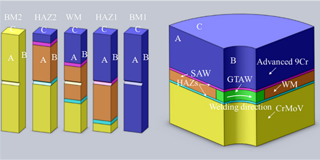
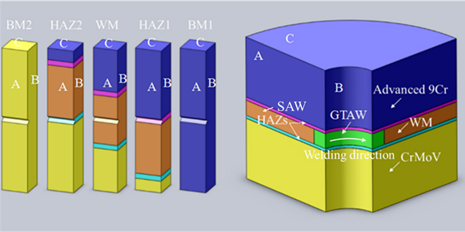
Charpy V-notch impact specimens were machined to 55 mm in length, 10 mm in width and thickness. The V notch was in the middle of each tested zone with a depth of 2 mm and a root radius of 0.25 mm. Figure 1 illustrates the preparation of test specimens from weldments. Charpy specimens were cut parallel to face A while the direction of crack propagation during tests was perpendicular to face A. To verify the notch position, the specimens were etched before processing to disclose a clear interface between WM and HAZs. The impact tests for BMs and WM were conducted in the temperature range from −60 °C to 80 °C by a pendulum impact tester (model: Zwick RKP450 IWI with the impact energy up to 450 J; Zwick, Ulm, Germany). Test temperature below 20 °C was achieved by mixing liquid nitrogen and high purity alcohol in an insulation box. Test temperature greater than or equal to 20 °C was obtained in a thermostatic oven. Due to the inhomogeneity in HAZs, extra specimens were tested for this zone to improve data reliability.
Schematic illustration of the welded joint and the impact test specimen. BM1 is 9Cr-BM, BM2 is CrMoV-BM, HAZ1 is 9Cr-HAZ, HAZ2 is CrMoV-HAZ.
The fractured specimens were submerged in high purity alcohol to protect the fracture surfaces from corrosion and oxidation. Brittle fracture percentage was calculated according to the standard ASTM A370. After counting, one fractured part was cut at mid-thickness and then etched by the etchant (HCl:HNO3:H2O = 3:3:5) to determine the accurate fracture locations in the joint. The other part was observed under a Zeiss optical microscope (OM; Zeiss Imager A2m, Carl Zeiss AG, Oberkochen, Germany) and in a JSM-7600F scanning electron microscope (SEM; JEOL Ltd., Tokyo, Japan) to characterize the microstructure and the morphology of the fracture surface.
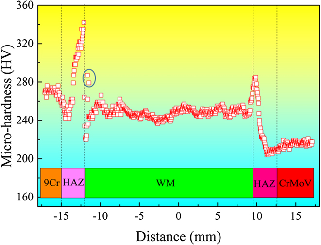
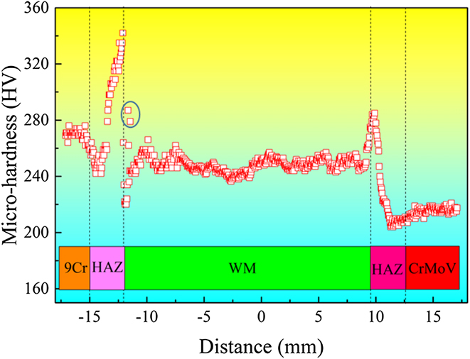
Micro-hardness was measured across the whole welded joint using 200 g for 15 s before the Charpy test to confirm different zones. Generally, higher hardness means lower toughness. So based on the result of micro-hardness test, the toughness can be preliminary evaluated. The micro-hardness profile across the joint is presented in Fig. 2. The micro-hardness of 9Cr-BM (270 HV) is higher than that of CrMoV-BM (220 HV). In WM, the hardness is about 250 HV with some fluctuation. And there are several higher points (280 HV) which were labeled by blue circle and a soft zone (220 HV) near the fusion line of 9Cr side. It is evident that there exists a large variation in micro-hardness data of HAZs. The highest hardness is about 340 HV in 9Cr-HAZ, which meets the production criterion of hardness less than 350 HV. Moreover, variation in hardness could be related to inhomogeneous microstructure. The detail microstructure of each zone will be discussed in the Sec. III.
Micro-hardness profile of the whole welded joint.
III. RESULTS AND DISCUSSION
A. Charpy impact toughness
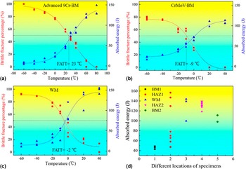
Figures 3(a)–3(c) display the variation of Charpy impact energy and brittle fracture percentage as a function of temperature and Fig. 3(d) shows the absorbed energy of different zones at room temperature. As shown in Fig. 3(a), the absorbed energy of 9Cr-BM is about 135 J at 80 °C (termed as upper shelf energy, USE) and 10 J at −60 °C (termed as lower shelf energy, LSE). The FATT is defined as the temperature when brittle fracture accounts for 50 vol% of fracture surface, and is 23 °C based on the curve. Figure 3(b) shows the values of USE and LSE of CrMoV-BM are 110 J and 25 J respectively. The FATT = −9 °C of CrMoV-BM is lower than that of 9Cr-BM and means better toughness at low working temperature. As can be seen in Fig. 3(c), the USE and LSE of WM are about 150 and 20 J, and the FATT = −2 °C of WM is similar to that of CrMoV-BM. The absorbed energies of 9Cr-BM, CrMoV-BM and WM at FATT are 63 J, 55 J, and 66 J respectively. Figure 3(d) shows absorbed energy at different weld zones at 20 °C. Apart from the change of mean values among different locations, there exists a huge difference in variation of absorbed energy at the same location, where absorbed energies for BMs are less scattered compared with values for HAZs. Considering the large variation in micro-hardness of 9Cr-HAZ, these data strongly indicate that the microstructure must have undergone dramatic change in the presence of welding-induced thermal cycle and inhomogeneous chemical compositions between filler and base metal during the welding. The details will be discussed later.
Results of impact toughness test at different locations: (a) curve of energy and brittle fracture percentage versus temperature of 9Cr-BM, (b) curve of energy and brittle fracture percentage versus temperature of CrMoV-BM, (c) curve of energy and fracture percentage versus temperature of WM, and (d) absorbed energy at different zones at 20 °C. BM1 is 9Cr-BM, BM2 is CrMoV-BM, HAZ1 is 9Cr-HAZ, and HAZ2 is CrMoV-HAZ.

B. Microstructure characterization
It was always deemed that toughness reduced with tempering temperature increasing. Reference Salemi and Abdollah-Zadeh34 However, this conclusion can only be applied on same material. For different materials, the microstructure before tempering is also different. So the tempering condition could not be the main reason that results in different toughness. However, it could affect microstructure in different zones. To better illustrate the correlation between impact toughness and microstructure at different locations of the dissimilarly welded joint, the microstructure of different zones is presented. As shown in Fig. 4, the improved strength and hardness in 9Cr-BM arises from tempered lath martensite of a few tens of microns. The microstructure of CrMoV-BM is composed of granular bainite which benefits not only strength but also toughness. Reference Salemi and Abdollah-Zadeh34,Reference Zhu, Wang and Xuan35 As can be seen in the SEM image of Fig. 4(b), carbide dispersion along a group of martensite laths of similar crystal orientation and grain boundaries in 9Cr-BM is the inherent microstructural factor contributing to the brittle fracture. Reference Eghlimi, Shamanian, Eskandarian, Zabolian and Szpunar36 In Fig. 4(c), the grain boundaries are less distinctive due to high tempering temperature in OM. In contrast to the excessive carbide precipitates in 9Cr-BM, fine carbides are uniformly distributed along the bainite grain boundaries and inside grains for CrMoV-BM as shown in Fig. 4(d). As such, the fine ductile bainite and uniformly distributed spheroidal carbides improve the impact toughness through dispersion strengthening effect in the matrix.
The microstructure of 9Cr-BM and CrMoV-BM after 30 h PWHT at 650 °C: (a) OM image of advanced 9Cr-BM, (b) SEM image of advanced 9Cr-BM, (c) OM image of CrMoV-BM, (d) SEM image of CrMoV-BM. The insets in (b) and (d) reveal the detailed carbides distribution in martensite-lath and in bainite.

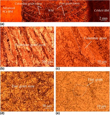
Figure 5(a) demonstrates the metallographic features of 9Cr/CrMoV welded joints after the multi-pass and multi-layer welding process. The total number of weld passes was about 250. The thickness of each pass was about 3 mm which includes 2 mm columnar zone and 1 mm fine grain zone. Coarse columnar grains grow perpendicular to the fusion line between different layers which was labeled by yellow line in Fig. 5(a) while fine grains interlace. The content of WM was listed in Table I which shows lower content of Cr and Mo. Such chemical composition makes it easier to form bainite after cooling. Columnar grain with obvious direction forms during the WM solidification. As shown in Figs. 5(b) and 5(c), the main microstructure in columnar grain is lath bainite. Width of columnar grains was about 50 μm and the length could reach several hundreds of microns. Grain boundary was thought weaker than grain due to the carbides and impurities concentration. And it is easier to crack along the grain boundary of columnar grain. Such cast structure may have an inferior impact toughness. The areas near to the fusion line in previous layer experience a peak temperature above A3 during welding, and the columnar grain with typical bainite structure transforms to equiaxed austenite. Reference Sattari-Far and Farahani37 During cooling process after welding, these equiaxed austenite grains become equiaxed bainite grains as shown in Figs. 5(d) and 5(e). Fine grains are about 10–30 μm in size. Normalizing and tempering effect on bottom layers is believed to form fine grain zone in WM, and subsequently lead to good toughness in WM specimens. Considering that the notch of specimens in WM was located at the middle of WM which is mainly composed of fine grains, large absorbed energy in WM could be attributed to that the crack mainly propagated in fine grain zones in the middle of WM.
Microstructure of the whole dissimilarly welded joint: (a) the overall microstructure of the welded joint, (b) columnar grain zone of WM, (c) magnified microstructure of columnar zone in WM, (d) fine grain zone of WM, (e) magnified microstructure of fine zone in WM.

Figures 6(a)–6(d) display coarse grain zone (CGZ) and fine grain zone (FGZ) in HAZ. Coarse grain zone near to the fusion line experiences a peak temperature above A3, and the carbides inhibiting the growth of austenite grain dissolve, which leads to the formation of the coarse grain austenite. During welding process, the peak temperature decreases with the increase of the distance from the fusion line. The carbides cannot be completely dissolved. Hence austenite grain growth is blocked by the incomplete dissolution carbides, which results in the formation of fine grain zone. Such a phenomenon leads to a large variation in grain size in HAZ and it is more pronounced in 9Cr-HAZ. Reference Lan, Qiu, Zhao, Gao and Du38–Reference Lambert-Perlade, Gourgues and Pineau40 The microstructure in HAZs mainly consists of martensite and bainite. In Fig. 6(a), tempered lath-martensite is found in coarse grain zone and grain size about 120–150 μm is larger than that in 9Cr-BM. Such large grains of brittle lath martensite adversely affect toughness as supported by the findings in Fig. 2. In Fig. 6(b), smaller grains about 20–30 μm and containing less lath martensite are observed near 9Cr-BM due to thermal cycles during the welding process. Figures 6(c) and 6(d) exhibit the microstructure of mainly tempered martensite and bainite in CrMoV-HAZ. The coarse grain is about 80 μm and fine one ranges 10–20 μm, both of which are much smaller than grains in the corresponding zones of 9Cr-HAZ. In summary, larger grain size and tempered lath-martensite in 9Cr-HAZ result in toughness smaller than that of CrMoV-HAZ which is composed of tempered martensite and bainite.
Microstructure of HAZs of two sides in the welded joint: (a) microstructure of coarse grain zone in advanced 9Cr-HAZ, (b) microstructure of fine grain zone in advanced 9Cr-HAZ, (c) microstructure of coarse grain zone in CrMoV-HAZ, (d) microstructure of fine grain zone in CrMoV-HAZ.

It should be noticed that there are soft zones in both HAZs. The evolution of HAZ microstructure depends mainly on the temperature experienced during welding process. The over-tempering zone between BM and fine grain zone undergoes a further over temperature tempering during welding which lead to lower harness than BM. Reference Francis, Mazur and Bhadeshia41 This zone has large effect on creep behavior while has little influence on impact toughness. Reference Liu, Liu and Lu42
Figure 7(a) reveals that there are two carbon-enriched zones in WM and HAZ depending on the welding technique of multi-layer and multi-pass. One is a 65 μm stripe in HAZ close to 9Cr-BM side. The other is a 45 μm one in WM between two weld beads. The carbon-enriched zone in HAZ is much more noticeable than that in the weld. The SEM images of carbon-enriched zone and carbon-depleted zone are shown in Figs. 7(c) and 7(d). In carbon-enriched zone, carbides could be easily observed inside grains. On the contrary, few carbides could be found in carbon-depleted zone. Reference Huang and Wang43,Reference You, Shiue, Shiue and Chen44 Generally, carbides improve hardness and strength, but reduce the toughness. In contrast to other HAZs, the 9Cr-HAZ contains a fine grain zone, a coarse grain zone and a carbon-enriched zone. The different microstructures of these zones give rise to the large variation of toughness in 9Cr-HAZ. Figures 7(e) and 7(f) exhibit the carbon enriched zone formed during multi-layer welding process. When the trailering weld bead melted 9Cr-BM, some Cr element migrated to the weld zone and created a localized Cr enrichment. However, due to the low content of Cr in WM (2.67 wt%) which is much lower than 9Cr-BM (10.57 wt%), it was deemed that there should be chemical composition dilution effect near the fusion line. This phenomenon results in that content of Cr in localized Cr enrichment zone is higher than WM and lower than 9Cr-BM. So the content gradient of Cr element between localized Cr enrichment zone and later welding layer should be lower than that between WM and 9Cr-HAZ. Under similar thermal cycle and PWHT, the degree of carbon migration in WM is also higher than that in HAZ. As labeled by blue circles in Fig. 2, the carbon-enriched zone in WM also possesses high hardness about 290 HV. Localized Cr enrichment in WM make it more likely to form martensite which corresponds well with hardness. Thermal cycle from multi-layer and long-time PWHT could make more carbides participate in both kinds of carbon-enriched zone and thus reduce toughness. The carbon-enriched zone in WM could also bring brittleness though the degree is lower than the zone in HAZ. The detail effects on absorbed energies were addressed in Sec. III. C.
Microstructure of the welded joint on advanced 9Cr side: (a) microstructure adjacent to fusion line, (b) microstructure of the carbon-depleted zone, (c) SEM image of carbon-enriched zone in HAZ, (d) SEM image of carbon-depleted zone in HAZ, (e) SEM image of carbon-enriched zone in the weld, (f) SEM image of carbon-depleted zone in the weld.

C. Fracture location
For 9Cr-BM, CrMoV-BM, the relatively small spread of fracture data and homogeneous microstructure suggest the fracture location is along the notch. The same conclusion applies to CrMoV-HAZ as well, even though there is a mixture of coarse grain and fine grain zones around the notch. However the large variation of impact toughness data and hardness in 9Cr-HAZ demand a closer examination of the fracture location in this zone.
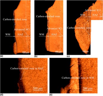
Figure 8 shows the representative optical macrostructure at the fracture location for three typical specimens, in which the deviation from notch to fusion line is identical. In Figs. 8(a) and 8(d), the fracture path is almost along the most carbon-enriched zone in HAZ. As the impact energy increases, the fracture location moves farther away from the fusion line and falls in the carbon-enriched zone of WM as shown in Figs. 8(b) and 8(e). In the specimen fractured at impact energy of 147 J, the fracture location is completely located in the WM in Fig. 8(c).
Confirmation of fracture locations in different 9Cr-HAZ specimens at 20 °C: (a) impact energy is 48 J; (b) impact energy is 68 J; (c) impact energy is 147 J; (d) magnified images of fracture location in (a); (e) magnified images of fracture location in (b).

Carbon-enriched zone could bring brittleness according to the microstructure and large amount of carbides. To explain the different crack paths, microstructure and hardness along the cross-section of the joint at 9Cr side could provide more information. The hardness of 9Cr-BM which possess lath martesite is about 270 HV. In WM, the hardness is about 250 HV with some fluctuation which agrees well with the complex structures which consist of lath bainite and granular bainite. After high temperature tempering, CrMoV-BM with granular bainite has low hardness of 220 HV. The highest value of 340 HV is found in carbon-enriched zone due to numerous dispersed coarse carbides. Micro-hardness decreases from HAZ to carbon-enriched WM and further to the lowest value of about 220 HV in the carbon-depleted zone of WM. It is speculated that carbon migration has large influence on toughness from lowest absorbed energy of 48 J. However, the carbon-enriched zone is not straight so that the crack should deviate to follow it. For Charpy impact test, the propagation path will change significantly once crack initiation deviates from vertical direction. The microstructure and hardness variation around fusion line further exacerbates such difference in fracture location. Deviation of crack propagation path in this region will lead to a mixed crack loading mode that is beneficial to the impact toughness. However, considering the negative effect of carbon enriched zone, a more reliable method that add a transition layer between 9Cr and WM will be developed and investigated in future research. The effect of carbon-enriched zone could be minimized by reducing the gradient of Cr element between 9Cr-BM and WM.
D. Fracture morphology
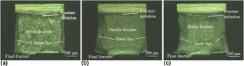
The macroscopic fracture surface of two BMs and WM are shown in Fig. 9. The brittle fracture surface can be classified as the fracture initiation region, brittle fracture region, two shear lips, and the region of final fracture, each of which correspond to a stage during impact damage, viz. crack initiation, crack propagation and final fracture. The lighter appearance of fracture surface in 9Cr indicates high degree of brittleness.
The macroscopic fracture morphology of different specimens at 20 °C: (a) 9Cr-BM; (b) CrMoV-BM; (c) WM.

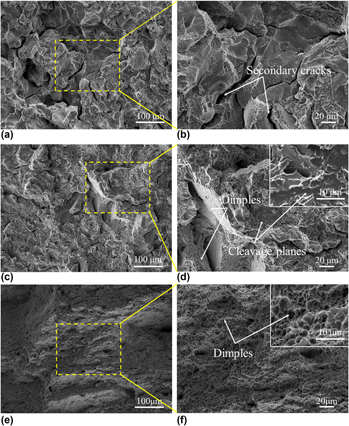
The microscopic fracture surfaces of the 9Cr-BM, CrMoV-BM, and WM were observed in SEM to evaluate the fracture mechanisms. As shown in Figs. 10(a) and 10(b), the images of advanced 9Cr-BM display brittle fracture appearance with river stripes and cleavage planes. For CrMoV-BM shown in Figs. 10(c) and 10(d), the surface of many dimples signals typical ductile fracture that means high toughness. Reference Cao, Feng, Peng, Du, Tian and Chen45 However, some dimples contain inclusions implying that they may be the source for large primary voids. Further EDS analysis concludes these inclusions are oxides. It is observed from Figs. 10(e) and 10(f) that the fracture is typical quasicleavage fracture which is characterized by cleavage planes and dimpled-tearing ridges. Moreover, the cleavage planes are much smaller than that in (a) and (b) which means a higher impact energy and higher toughness.
Fractography of Charpy specimens at different locations at 20 °C: (a) and (b) are images of advanced 9Cr-BM; (c) and (d) are images of CrMoV-BM; (e) and (f) are images of WM. The inset in (d) shows EDS results for the inclusion. BM: base metal.

The fracture mode of CrMoV-BM is totally ductile fracture. While WM shows quasicleavage fracture. Generally, the toughness of CrMoV-BM should be higher than that of WM. But the absorbed energy of WM is higher than CrMoV-BM. Such difference could be attributed to different microstructure, chemical composition, and inclusions in CrMoV-BM. The main microstructure of fine grain zones in WM is tempered bainite which possess high toughness. Moreover, multi-layer and multi-pass welding further improve the toughness of WM. Inclusions in CrMoV-BM would be the initiation of voids and accelerate the voids forming. Coalescence of voids leads to fracture finally. Many inclusions in material could make voids easier to coalesce with each other which could be the main reason of lower absorbed energy in CrMoV-BM. P and S have been confirmed that will bring brittleness. Reference Islam48 Comparing the element content of 9Cr-BM, CrMoV-BM, and WM, it was found that the content of P and S in WM is the lowest of 0.003 wt% and 0.001 wt%. Moreover, long time PWHT at 650 °C leads to more obvious concentration of P and S on grain boundary which could reduce toughness and absorbed energy. This could also explain why the impact toughness of WM is better than CrMoV-BM and 9Cr-BM.
Figure 11(a) illustrates brittle fracture along carbon-enriched zone. The smooth facets have a consistent size about 100 μm in this zone which implies an inter-granular fracture mode. Since the strength of grain boundary is weaker than grain interior and is adversely affected by the presence of carbides, crack propagates easily on carbon-enriched boundaries and leaves behind a smooth surface. Reference Arioka, Yamada, Terachi and Chiba46,Reference Petch47 Even when the main crack hits a boundary crossing, the energy is sufficient to generate secondary cracks along other boundaries as shown in Fig. 11(b). Figures 11(c) and 11(d) present the brittle fracture with somewhat ductile character as evidenced by several dimples. Figures 11(e) and 11(f) demonstrate a fully ductile fracture with prevalent dimples.
Fractography of Charpy specimens in advanced 9Cr-HAZ with different absorbed energy at 20 °C: (a) and (b) impact energy is 48 J; (c) and (d) impact energy is 66 J; (e) and (f) impact energy is 147 J. The insets in (d) and (f) exhibit the structure details of the cleavage planes and dimples.

The fracture modes are in good agreement with microstructure. 9Cr-BM with coarse lath martensite displays total brittle fracture appearance, while CrMoV-BM with bainite shows fully ductile fracture. Fracture surface of WM which mainly contains tempered martensite and bainite possesses quasicleavage feature. For carbon-enriched zone in 9Cr-HAZ, smooth fracture surface and second cracks confirm the deleterious effect of carbides on grain boundary.
IV. CONCLUSIONS
The impact toughness and microstructure of dissimilar joints of advanced 9Cr/CrMoV made by NG-SAW were systematically investigated. Our key findings are summarized as follows:
-
(1) From impact toughness tests in a wide temperature range, the FATTs of advanced 9Cr-BM, CrMoV-BM and WM are 23 °C, −9 °C, and −2 °C, and the corresponding absorbed energies are 63 J, 55 J, and 66 J respectively.
-
(2) At 20 °C, large grain size with coarse lath martensite in 9Cr-BM shows brittle characteristics in Charpy test. Tempered granular bainite in CrMoV-BM and CrMoV-HAZ possess high toughness. Fine grain zone in WM that transformed from columnar grain under peak temperature above A3 with granular bainite was proved that has excellent toughness. 9Cr-HAZ is considered as the weakest zone in toughness of the whole welded joint due to the carbon-enriched region.
-
(3) At 20 °C, the fracture modes of 9Cr-BM, CrMoV-BM, and WM are cleavage fracture, ductile fracture, and quasi-cleavage, respectively. Content of phosphorus and sulfur and inclusions in CrMoV-BM are main reasons that lead to toughness of WM higher than CrMoV-BM. The fracture mode occurred in carbon-enriched zone is typical inter-granular fracture. Such a narrow carbon-enriched zone bring brittleness to the whole joint. However, the carbon-enriched region is not straight, and microstructure around this region is inhomogeneous. Deviation of crack propagation path in this region lead to a mixed crack loading mode that is beneficial to the impact toughness.