I. INTRODUCTION
There have been significant developments in wireless communication technologies during the last decade that meet market requirements. Communication terminal antennas are not only desired to be low-profile, lightweight, and single-feed, but also need to meet the multiband requirements to support different wireless data communication applications, such as Bluetooth, WLAN, WIFI, and WIMAX, and new mobile communications applications such as UMTS and LTE. The traditional planar inverted-F antenna (PIFA) is used extensively because it is reasonably compact, has a fairly omnidirectional radiation pattern, has good efficiency, and is very simple. The coplanar waveguide is also one of the most commonly used feed lines for commercial applications. Combining both the inverted-F antenna and coplanar waveguide (CPW) is a good solution for practical commercial products [Reference Qiu, Chiu and Mohan1–Reference Deng, Tsai, Chang and Bor3]. Paper [Reference Deng, Tsai, Chang and Bor3] introduces the CPW-fed PIFA with broadband characteristics, but the antenna has a large ground plane and could be applied to one application only. In the consumer products, the antenna is required to be smaller, lighter, thinner, and low cost and to be used for different wireless applications. The PIFAs with different shaped slots [Reference Ali and Hayes4–Reference Soliman, Elsheakh and Abdallah12] are widely used to create resonant frequencies or to reduce the antenna size in mobile handsets. PIFAs have been combined with slots in the ground plane [Reference Cabedo, Anguera, Picher, Ribo and Puente13–Reference Abedin and Ali17] for wireless communication applications. However, these designs have limited applications.
The debate about the possible health risks of exposure to electromagnetic radiation on human beings is still an open subject that involves many people around the world. Recent papers [Reference Cabedo, Anguera, Picher, Ribo and Puente13, Reference Abedin and Ali17] based on a great amount of scientific work challenge the traditional scientific point of view, which establishes the thermal effects of electromagnetic radiations as the only one of concern for the human health. While part of the electromagnetic wave radiated by the antenna is absorbed by the human head, some mobile handsets have antenna characteristics, such as radiation pattern, radiation efficiency, bandwidth, and return loss that are altered due to the proximity of the human head [18]. In order to limit the biological effects resulting from exposure to RF radiation, safety limits are usually defined in terms of the specific absorption rate (SAR). The IEEE C95.1:2005 standard defines the SAR limit to be 2 W/kg in a 10 g averaging mass [18].
In this paper, a reconfigurable multiband CPW-fed PIFA with acceptable SAR is proposed for handheld applications. The antenna is based on a combination of a CPW-fed PIFA, meander-turn-shaped slots on the radiating plate and coupled slot within the ground plane for multiband and size reduction characteristics. More resonant frequencies are excited by increasing the numbers of meander-turn-shaped slots. A PIN diode is used to switch the fundamental resonant frequency from high to low frequency. Three antenna prototypes are fabricated to cover the LTE band 11 (1.47–1.5 GHz), LTE band 8 (925–960) MHz, GSM1800 MHz/GSM1900 MHz/Bluetooth 2.4 GHz, WIMAX frequency range (3–4) GHz, and WLAN frequency range (5–6) GHz. The interaction between the head and the antenna is examined by simulating the SAR with CST 2012 Microwave Studio, Hugo voxel model.
II. DESIGN PROCEDURE OF PROPOSED ANTENNA
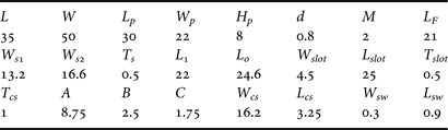
The whole geometry with detailed design parameters of the proposed multiband CPW-fed PIFA antenna with meander-turn-shaped slots on the radiating patch and coupled slot within the ground plane is shown in Fig. 1. The detailed dimensions are listed in Table 1. The antenna is fabricated on 0.8-mm-thick FR4 substrate with L = 35 mm and W = 50 mm, and its relative dielectric constant and loss tangent are 4.4 and 0.02, respectively. Additional foam substrate of 8 mm is added with thickness, and its relative dielectric constant and loss tangent are 1.07 and 0.02, respectively. Two foam layers are used to reach the required substrate thickness of 8 mm and a FR4 substrate layer with thickness 0.8 mm. Also, to implement the patch on the foam substrate layer, an additional Roger liquid crystal polymer substrate is added with thickness 0.05 mm, and its relative dielectric constant and loss tangent are 2.9 and 0.009, respectively. The bandwidths generated by the individual PIFA-radiating plate are not wide enough to cover the entire band for various wireless communication applications. However, it is found that CPW-fed PIFA antenna can couple with the meander-turn-shaped slots to obtain the commercial multiband characteristics with enhanced bandwidth and dramatic size reduction. Meander-turn-shaped slots are coupled to the PIFA antenna to increase the number of frequency bands and therefore, the slots act as parasitic elements to increase the bandwidth [Reference Cabedo, Anguera, Picher, Ribo and Puente13, Reference Anguera, Sanz, Mumbru and Puente14]. A similar approach is practiced here to increase the operating frequencies. The patch has one turn, two turn and three turn meander-shaped slots with PIN switch (ON/OFF) mode. The ground plane has one coupled slot. It is fed by a CPW transmission-line, which can be easily integrated with other CPW-based microwave circuits printed on the same substrate.
The geometry and configuration of CPW-fed PIFA with PIN diode switch (SW), (a) radiator with one meander-turn-shaped slot, (b) ground plane, (c) antenna side view, (d) radiator with two meander-turn-shaped slots, and (e) radiator with three meander-turn-shaped slots.

The dimensions of the proposed antenna (mm).
A) Multiband CPW-fed PIFA
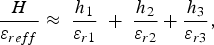
To understand the operation of the proposed design, high-frequency structure simulation (HFSS) ver.13 is used, which is based on the finite-element method to verify the design. The design is started by conventional CPW-fed PIFA (the meander-turn-shaped slots on the radiator and the coupled slot within the ground plane are removed) to operate at Bluetooth 2.4 GHz. The resonant frequency of the antenna can be approximately determined by equation (1) [Reference Nashhat, Elsadek and Ghali5–Reference Liu, Hall and Wake7]. The effective dielectric constant may be approximately calculated by equation (2) [Reference Yoon and Kim19] from multidielectric material layers.
 $$F \approx \displaystyle{C \over {4\sqrt {{\varepsilon _{reff}}} \lpar {L_p}\rpar }}$$
 $$\displaystyle{H \over {{\varepsilon _{reff}}}} \approx \; \displaystyle{{{h_1}} \over {{\varepsilon _{r1}}}}\; + \; \displaystyle{{{h_2}} \over {{\varepsilon _{r2}}}} + \displaystyle{{{h_3}} \over {{\varepsilon _{r3}}}}\comma$$
where, L p is the length of the radiating surface. ε reff is the equivalent effective dielectric constant of the three substrates, H is the total antenna height. h 1, h 2, and h 3 are the heights of each layer of the substrate.
Figure 2 shows the multiband CPW-fed PIFA reflection coefficient design procedures. The resonant frequency of the PIFA-radiating plate is obtained at F = 2.4 GHz, as shown in Fig. 2(a). The coupled slot is etched on the ground plane to excite a new independent resonant frequency at 5.2 GHz without affecting the resonant frequency of PIFA. Extra resonant bands are created by inserting different numbers of meander-turn-shaped slots on the radiating plate. When one-turn meander-shaped slot is etched on the radiating patch, two resonant frequencies are excited at 2.4 and 3.5 GHz in addition to about 38% size reduction in the fundamental PIFA resonant frequency, from 2.4 to 1.5 GHz, as shown in Fig. 2(b). The two resonant frequencies can be controlled throughout the length and width of the meander-shaped slots to operate at any desired frequency band. The 50 Ω feed arm width M is used to control the antenna matching. When two-turn meander-shaped slots are added on the radiating patch, an extra resonant frequency is excited at 4.4 GHz with about 5% size reduction in the resonant frequencies 2.4 and 3.5 GHz, whereas the resonant frequencies 1.5 and 5.2 GHz remain almost unchanged. The same happens by etching three-turn meander-shaped slots; the extra resonant frequency is excited at 4.5 GHz with about 5% size reduction in the resonant frequencies 2.4, 3.5, and 4.4 GHz while the other resonant frequencies remain almost unchanged, as shown in Fig. 2(b).
The simulated |S 11| design procedures, (a) CPW PIFA with and without coupled slot and (b) with different numbers of meander-turn-shaped slots.
B) Reconfigurable multiband CPW-fed PIFA
Figure 3(a) shows the simulated |S 11| of the one-turn meander-shaped slot with ON/OFF switch mode. An ideal switch model is firstly used to imitate the PIN diode switches with the open (OFF) and close (ON) states to switch the antenna from LTE band 11 (1.47–1.5) GHz to LTE band 8 (0.925–0.960) GHz with a total 63% size reduction compared with the original PIFA size. The open (OFF) and close (ON) states of the switches are simulated in the absence or presence of a metal pad with the area W sw × L sw = 0.3 × 0.9 mm2, respectively. This is approximately the same area of a real PIN diodes switch. Then, the practical model of the PIN diode HPND-4005 is used as forward biased with 0.7 V and 10 mA. It exhibits an ohmic resistance of 3 Ω and intrinsic capacitance of 0.1 pF for forward bias, while exhibits 2.7 K Ω and 9 pF at 0 V. 10 pF capacitors are used as shown in Fig. 7(e), to isolate the RF signal from the DC and RF choke coil MCL 50–10 000 MHz. Same PIN diode connections are used for the two and three turns meander-shaped slot antenna. The reflection coefficient for three cases and both two PIN diode modes are shown in Figs 3(a)–3(c), respectively. The concept is approved for the three designs.
The simulated |S 11| of (a) one-, (b) two- and (c) three-turn meander-shaped slots with PIN switch ON/OFF modes.
The operations of the antenna at each resonant frequency are further studied using surface current distribution. The current distribution at different resonant frequencies for both PIN diode states at 0.9, 1.5, 1.9, 3, 3.6, and 5.2 GHz, respectively, are shown in Fig. 4. Each resonant frequency could be controlled through each corresponding dimensions. The surface current magnitude is high (red colors) around each slot at its corresponding resonant frequency.
The surface current distribution for the proposed CPW-fed PIFA at (a) 0.9 GHz, (b) 1.5 GHz, (c) 1.9 GHz, (d) 3 GHz, (e) 3.6 GHz, and (f) 5.2 GHz, respectively.
The surface current magnitude is distributed around the patch at 0.9 and 1.5 GHz. The resonant frequency 5.2 GHz is more affected by the coupled slot within the ground plane. Other resonant frequencies are more affected by the meander shaped slots within the patch. It seems that for 0.9, 1.5, 1.9, 3 and 3.6 GHz the PIFA is mainly operating and for 5.2 GHz the slot in the ground plane operates.
C) Effect of head model and SAR calculation
The SAR is the basic restriction for electromagnetic exposure of a user of a mobile phone and is a fundamental parameter when discussing the health risks of electromagnetic Power absorption in the body [18]. This quantity is defined as [20]:
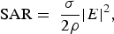 $${\rm SAR} = \; \displaystyle{\sigma \over {2\rho }}\vert E{\vert ^2}\comma$$
where ρ (kg/m3), and σ (S/m) are the body tissue density and conductivity, respectively. E (V/m) is the r.m.s. value of the electric field strength in the tissue.
The human body also interferes with the operation of close-by antennas causing issues that have attracted various research studies in the literature [20]. The reflection coefficient of the ON/OFF states in the presence of the head model is shown in Figs 5(a) and 5(b). It is clearly noticed that the operating resonant frequencies are shifted as well as the amount of reflected power are changed. However, the resonant frequency at 1.5 GHz in OFF state case is partially absorbed by the dispersive materials of the human head as shown in Fig. 5(b). In the vicinity of human head, resonant frequencies are usually in many cases affected by the proximity to the human head [20].
The r.m.s. reference antenna power is 0.5 W. The 10 g SAR results are illustrated in Table 2. It is clearly seen that the 10 g SAR results at all frequencies meet the SAR limits of 2.0 W/kg standards with 0 mm distance between the proposed antenna and the head model. The SAR in the head has a peak of 1.73 W/kg. Moreover, mounting this antenna in the backside of handheld devices or profiling these devices might be the simplest way to reduce SAR to lower levels [Reference Amos, Smith and Kitchmer21]. In addition, PIFAs can reduce the possible electromagnetic energy absorption by the mobile handset user's head, because of relatively smaller backward radiation toward the user [Reference Cho, Shin, Kim and Shin22]. It is also noticed that the SAR values at resonant frequencies 2.1, 3.5, 3.9, and 4.4 GHz generating from the slots on the patch are very close to each other because these slots have the same distance from the head model. Although having slots in the ground plane, SAR is satisfactory. Similar studies can be found in [Reference Picher, Anguera, Andujar, Puente and Kahng23].
Increasing the distance between the antenna structure and the head is the easiest way to lower the electromagnetic energy absorbed in the human tissues of the head. Also, by placing the antenna away from the user or in the back of the handset, the average SAR may be reduced. At each resonant frequency, the SAR values are reduced with increasing the distance between the proposed antenna and the human head model from 0 to 12 mm, as shown in Fig. 6. This is simply because RF power decreases as the distance between antenna and human head increases. Using curve fitting tool, we can extract an approximate formula that describes the effect of the distance between the proposed antenna and the head model on the SAR values at different resonant frequencies. The curve approximately can fit sigmoidal (Boltzmann) equation (4) with coefficient illustrated in Table 3, with about 2% error which is acceptable.
The simulated SAR values of the proposed CPW-fed PIFA with 0 mm distance from the head model.

The parameters values of the curve fitting function F(x) at operating frequencies.
The phantom adult model is used to measure temperature raise in the head. Recently, in [Reference Prishvin, Zaridze, Islam and Ali24], state that the volumetric distribution for the SAR and temperature raise is basically the same. However, the main part of energy is being absorbed in the thin boundary layer at low frequencies is much higher compared with same points at higher frequencies. The maximum limits of possible temperature in the head and brain at the SAR values vary according to the human age. This may happen because of the effect of pinna, which is not included in the calculation of peak-spatial average SAR [Reference Fujimoto, Hirata, Jianqing, Fujiwara and Shiozawa25]. For an adult model, the temperature rise is 0.5°C for 10 g cubic tissue with 2.0 W/kg, which is below the limits in [Reference Fujimoto, Hirata, Jianqing, Fujiwara and Shiozawa25].
 $$F\lpar x\rpar = Y + A\, {e^{ - x/t}}\comma$$
where F(x) represents the SAR value and x is the distance between human head model and the proposed antenna.
The three-turn meander-shaped slots with/without head model (a) ON state and (b) OFF state.
Variation of SAR with the distance from the head at 0.9, 1.5, 2.4, 3.9, 4.4, and 5.2 GHz.
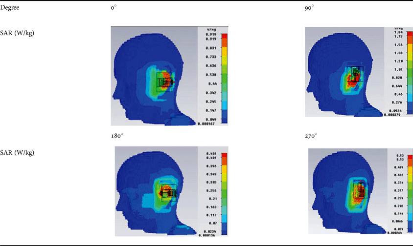
For further study of the distribution of the antenna power on the human head tissues, the rotation of the proposed antenna around the head model is investigated at 1.5 GHz, as shown in Table 4. It is clearly seen that the SAR values are varied when rotating the proposed antenna with respect to the head model due to different amounts of the power absorbed by head tissues in each case, but all values meet the SAR limits of 2.0 W/kg standards.
The SAR variation with rotation of the proposed antenna around the head model.
III. RESULTS AND DISCUSSION
To verify the simulated results, the proposed multiband CPW-fed PIFA with one-turn, two-turn and three-turn shaped slots antennas were fabricated by using photolithographic techniques. The photos of fabricated antennas are shown in Figs 7(a)–7(d). Figure 7(e) shows the fabricated three-turn meander-shaped slots antenna with a PIN diode and an external biasing circuit. Their performances were measured using HP8719ES vector network analyzer with both the PIN switch modes (ON/OFF), as shown in Fig. 8. The experimental results show very good agreement with the simulated result at the targeted operating frequencies. There is small discrepancy between the simulated and measured results. This may be attributed to the fabrication tolerances and the bonding material distributed between the copper and the foam layers.
Photo of the fabricated proposed antennas (a) one-turn shaped slot, (b) two–turn-shaped slots, (c) three–turn-shaped slots, (d) ground plane with coupled slot, and (e) three-turn-shaped slots antenna with PIN diode and external biasing circuit.
Comparison of simulated and measured |S 11| of (a) one-turn-shaped slot, (b) two-turn-shaped slots, (c) three-turn-shaped slots with SW/ON (d) three-turn-shaped slots with SW/OFF.
IV. IMPEDANCE BANDWIDTH, GAIN, DIRECTIVITY, AND RADIATION PATTERN
Table 5 shows the simulated antenna gain, impedance bandwidth, and radiation efficiency at each resonant frequency for the three-turn meander-shaped slots with a coupled slot (switch ON/OFF mode). The gains of the proposed antennas are between 1.8 and 4.8 dBi at each resonant frequency with good impedance bandwidth (|S 11| <−6 dB), which is suitable for standard channel bandwidth for wireless communication applications such as LTE band 8 (0.925–0.960) GHz, GSM1900, LTE band 2 (1.93–1.99) GHz, LTE band 33 (1.990–1.920) GHz, LTE band 11 (1.427–1.5) GHz, Bluetooth, WIMAX, and WLAN. The antenna has good radiation efficiency at each operating frequency. The radiation efficiency is larger than 70%. It decreases by switching the antenna from high to low frequency due to ohmic losses of the switches.
The simulated antenna parameters at resonant frequencies of three-turn meander-shaped slots (SW ON/OFF modes).
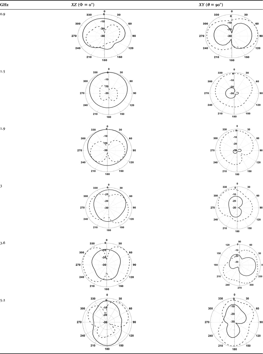
Table 6 shows the measured radiation pattern in ZX plane (ϕ = 0°) and XY plane (θ = 90°) at 0.9, 1.5, 1.9, 3, 3.6, and 5.2 GHz for co- and cross-polarization, respectively. The obtained radiation patterns are nearly omnidirectional in the XY plane, and the radiation patterns exhibit monopole-like patterns in the XZ plane. It is noticed that the average difference between the co- and cross-polarization is 15 dB, which is acceptable for most wireless communication applications. Some discrepancy appears at many bands that may be attributed to the inadequate size of the absorbers, in addition to poor isolation.
The measured radiation pattern in ZX and XY planes at the resonant frequency of the three-turn meander-shaped slots, E Ф: Black slide lines, E Θ: Black dotted lines.
V. CONCLUSION
Reconfigurable multiband CPW-fed PIFA with size reduction and low SAR is proposed and successfully implemented. It could be applied to WLAN, Bluetooth, and GSM1900, LTE band 2, LTE band 33, LTE band 11, LTE band 8, and WIMAX applications. Acceptable bandwidth and acceptable SAR at different operating frequencies is achieved. Experimental measurements show good agreement with simulated results that verifies the design. The antenna radiates nearly omnidirectionally at all resonant frequencies, with good average gain around 2.2 dBi, and good average radiation efficiency around 70%, which is suitable for wireless communication applications. The proposed antenna can be switched from the second generation to the fourth generation using a PIN diode switch for mobile applications.
ACKNOWLEDGEMENT
This research is supported by the National Telecommunication Regularity Authority (NTRA), Ministry of Communication and Information Technology, Egypt.
 Ahmed M. Soliman was born in Cairo in 1987. He received the B.Sc. degree (with honors) in electrical and communication engineering from Shoubra Faculty of Engineering, Zagazig University, Cairo, Egypt, in 2009. Currently, he is working toward the M.Sc. degree at the Faculty of Engineering, Ain Shams University. Since his graduation, he was appointed as an R.A. by the Electronics Research Institute, Microstrip Department, Giza, Egypt. His graduation project was to design a communication system for cube satellite under the supervision of the National Authority for Remote Sensing and Space Sciences (NARRS). He and his graduation project's team received the Information Technology Industry Development Agency Award, the 2009 Young Investigator Award, and Giza Systems School of Technology scholarship Award.
Dalia M. Elsheakh received the B.S., M.S., and Ph.D. degrees in electrical and communication engineering from the Ain Shams University, Cairo, Egypt, in May 1998, September 2004 and October 2010, respectively. Her master's thesis was about the design of microstrip PIFA antennas for mobile handsets. Her Ph.D. dissertation was entitled, “Electromagnetic Band-Gap (EBG) Structure for Microstrip Antenna Systems (Analysis and Design).” From 2008 to 2009, she was Assistant Researcher in the Hawaii Center for Advanced Communications (HCAC), College of Engineering, University of Hawaii at Manoa, Honolulu. She has holds one patent, and has published 21 papers in peer-refereed journals, and 22 papers in international conferences in the field of microstrip antenna design. Her current research interests are in microstrip antennas theory and metamaterials design and electromagnetic wave propagation. She has participated in many research projects at the national and international levels under the Egypt–NSF–USA joint funds program and the European Committee Programs FP7 program, STDF, and ITIDA–ITAC.
Esmat A. Abdallah graduated from the Faculty of Engineering and received the M.Sc. and Ph.D. degrees from Cairo University, Giza, Egypt, in 1968, 1972, and 1975, respectively. She was nominated as Assistant Professor, Associate Professor and Professor in 1975, 1980, and 1985, respectively. She has focused her research on microwave circuit designs, planar antenna systems, and non-reciprocal ferrite devices, and recently on EBG structures, UWB components, and antenna and RFID systems. She has authored and coauthored more than 127 research papers in highly cited international journals and in proceedings of international conferences in her field, such as IEEE Transactions on Antenna and Propagation and IEEE Transactions on Microwave Theory Techniques., Microwave and Optical Technology Letters, etc. She has participated in many research projects at the national and international levels under the Egypt–NSF–USA joint funds program, the European Committee Programs FP7 program, etc. She is also a reviewer for many international societies.