I. INTRODUCTION
Antenna arrays are being widely used in mobile and satellite communications. Linear antenna arrays are limited in their steering capability. This limitation is overcome by the use of planar antenna arrays. Owing to its symmetry, a circular array is an obvious choice when steering through 360° of azimuth is required. The utilization of all the space occupied by the antenna is thus possible. Its applications span radio direction finding, air and space navigation, underground propagation, radar, sonar, and many other systems [Reference Balanis1]. Recently circular arrays have been surveyed for application in smart antennas [Reference Ioannides and Balanis2, Reference Jin, Li and Wang3]. The advantage of circular antenna array over linear antenna array is that it does not have any edge elements. Thus directional patterns synthesized by this geometry can be electronically scanned in the azimuthal plane without a significant change in beam shape. Also, the circular arrays have been found advantageous in dealing with applications where mutual coupling can limit the performance [Reference Rudge, Milne, Olver and Knight4]. Therefore, the circular arrays have been used for many years in high-frequency band for both communication and direction finding.
Early significant contribution in this area was the synthesis of Dolph–Chebysev type of pattern using a single circular ring array [Reference Duhamel5]. A Taylor-type distribution of radiation pattern was obtained by the use of concentric rings in [Reference Taylor6]. The ring arrays have been investigated for obtaining azimuthal pattern with low sidelobes in [Reference Stearns and Stewart7]. Ring array have been shown to produce a nearly omni directional pattern [Reference Royer8, Reference Chu9]. Extensive numerical results, based on Taylor's formulation, were obtained by Hansen in [Reference Hansen10]. An extension of the Dolph–Chebyshev synthesis technique to circular array of antennas has been presented in [Reference Vescovo11].
The conventional methods of antenna array optimization, discussed above, require gradient information and/or depend on the choice of initial seed point, and it depends on the target application or design problem. The solution lies in the use of stochastic and evolutionary approaches of optimization [Reference Sykulski, Rotaru, Sabene and Santilli12, Reference Rattan, Patterh and Sohi13]. The evolutionary approaches like Genetic Algorithms and Particle Swarm Optimization have been used successfully for optimization problems in antenna and electromagnetic design problems [Reference Haupt14–Reference Rattan, Patterh and Sohi21]. Recently, the optimization of circular antenna arrays has been addressed using GA [Reference Panduro15] and PSO [Reference Shihab, Najjar, Dib and Khodier18].
Simulated annealing (SA) is a random-search technique that exploits an analogy between the way in which a metal cools and freezes into a minimum energy crystalline structure (the annealing process) and the search for a minimum in a more general system; it forms the basis of an optimization technique for combinatorial and other multimodal problems [Reference Kirkpatrick, Gellatt and Vecchi22]. The SA searches all the states that are near a given value of objective function to the same extent. This feature is not present in GA and PSO. GA and PSO are evolutionary approaches that tend to add a bias in favor of those states with good values of objective function, i.e. they tend to preferentially breed members with higher fitness values. Owing to this special feature and its simplicity, SA will remain a permanent niche in the arsenal of optimization algorithms [Reference Saloman, Sibani and Frost23].
SA has been used for various problems in electromagnetics quite successfully [Reference Murino, Trucco and Regazzoni24–Reference Rattan, Patterh and Sohi27]. SA has been used for linear antenna array synthesis problems quite successfully [Reference Murino, Trucco and Regazzoni24, Reference Redvik25]. It has also been used to find the optimum distribution for linear antenna arrays with failed elements [Reference Ruf26]. Recently, the authors have used it for the design of linear antenna array of isotropic radiators with minimum sidelobe level and null control using variation of spacing between array elements [Reference Rattan, Patterh and Sohi27]. In this paper, the application of SA in the design optimization of circular antenna arrays has been presented. The next section describes the basics of SA. The subsequent section presents the formulation of design problem. The next section presents the computer simulation results and discussions. Finally the work has been concluded.
II. SIMULATED ANNEALING
SA is a technique for combinatorial optimization problems, such as minimizing functions of many variables. Since many real world problems can be cast in the form of optimization problems, SA is finding intense interest in the literature. Consider the problem of coercing a solid into a low-energy state. In this context, a low-energy state usually means a highly ordered state, such as crystal lattice. To accomplish this goal, material is annealed, heated to a temperature that permits many atomic rearrangements, and then cooled carefully, slowly until the material freezes into a good crystal. SA technique uses an analogous set of “controlled cooling” operations for non-physical optimization problems, in effect transforming a poor, unordered solution into a highly optimized, desirable solution. Thus, SA offers an appealing physical analogy for the solution of optimization problems and, more importantly, it has the potential to reshape mathematical insights for real optimization problems.
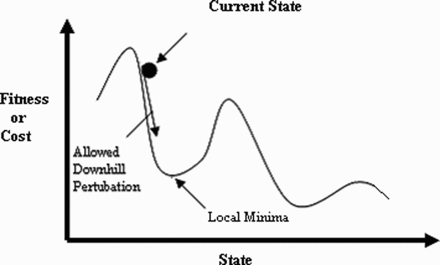
In simple iterative improvement techniques, only downhill improvements, i.e. that result in the decrease of energy, are allowed forcing the algorithm to be trapped in local minima as illustrated in Fig. 1. These techniques are not able to overcome this local minimum point. SA is similar to iterative improvement strategy, but with one major difference. SA allows perturbations to move uphill also but in a controlled manner. Since, each move can now transform one configuration to a worse configuration, it is possible to jump out of local minima and potentially fall into a more promising downhill path.
A single parameter optimization problem.
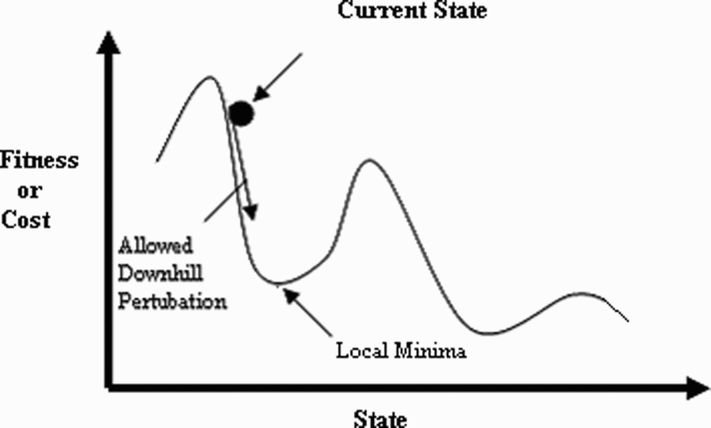
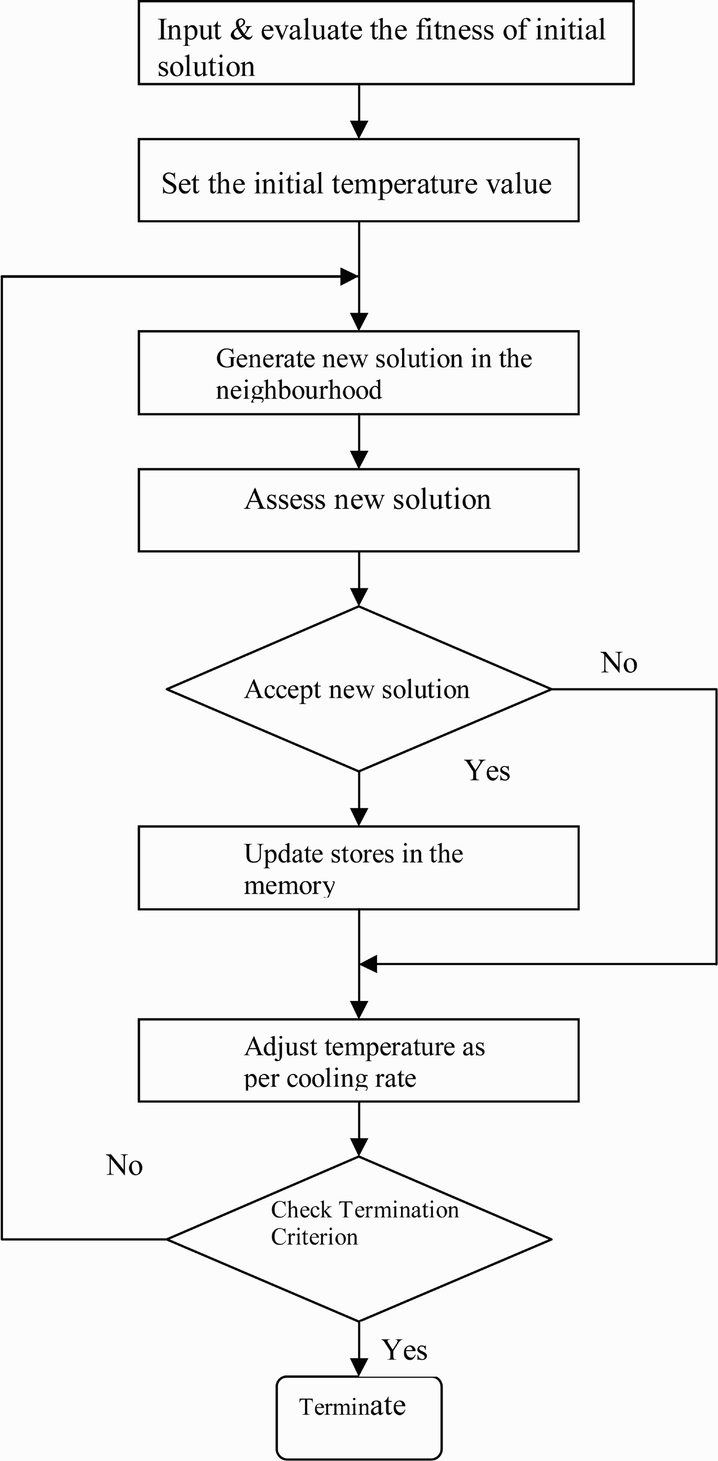
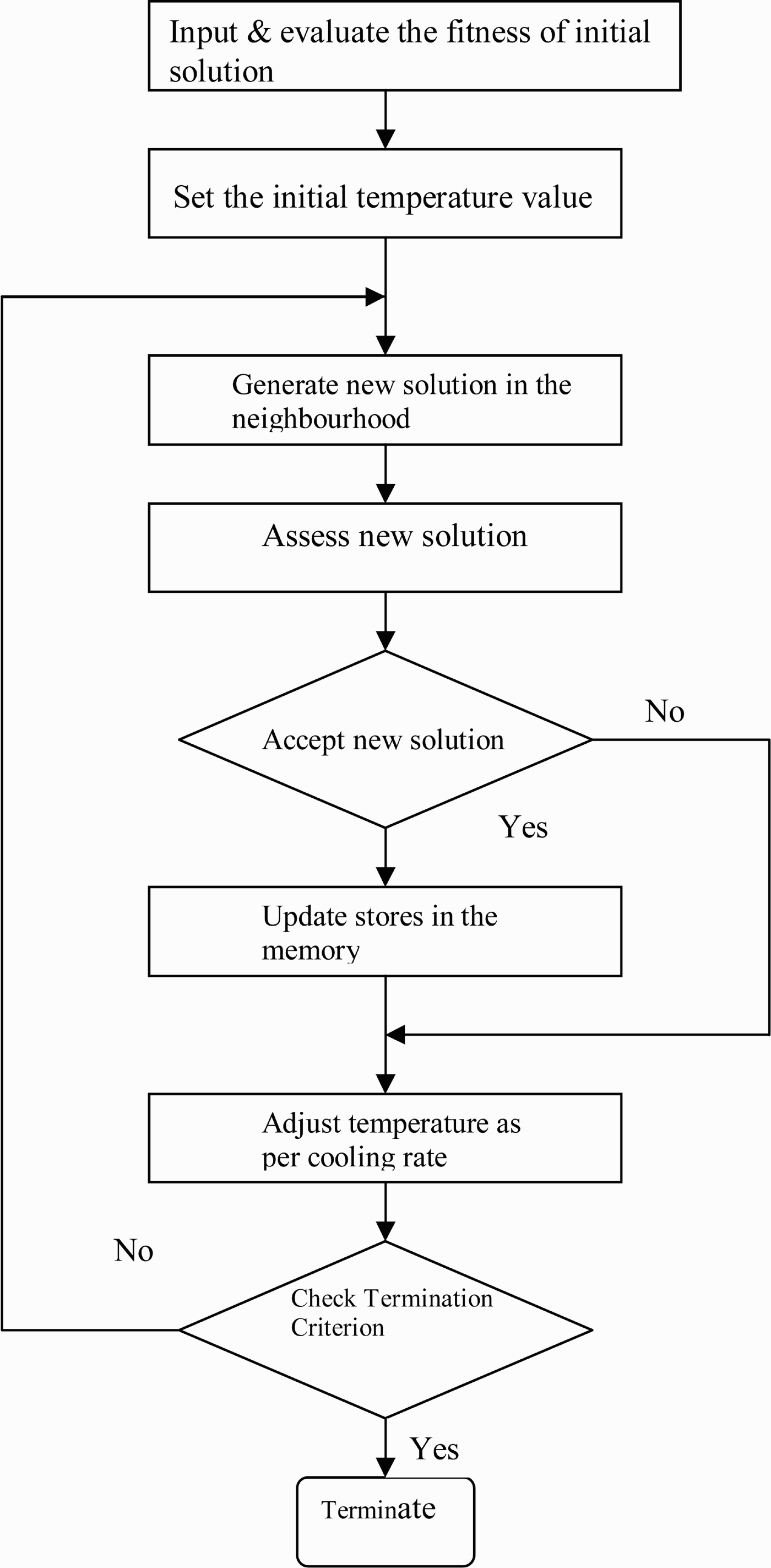
Figure 2 shows the basic structure of SA. The algorithm begins with an initial point and a high temperature value. A new point is created at random in the vicinity of initial point and whether to accept or reject this is decided as per Metropolis acceptance criterion. Metropolis algorithm is a method for obtaining a sequence of random samples from a probability distribution for which direct sampling is difficult [Reference Metropolis, Rosenbluth, Rosenbluth, Teller and Teller28]. In case of Metropolis algorithm, the resulting change, δx, in the energy of the system is observed. The displacement is accepted, if δx ≤ 0. In case, δx > 0, it is treated probabilistically. The probability that the configuration is accepted is given by
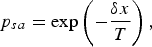
where δx is the increase in x and T is a control parameter. In physical system, temperature has a physical meaning in arbitrary non-physical optimization tasks; the temperature is simply a control parameter. The probability of accepting a worse move is a function of both the temperature of the system and the change in the objective function. As the temperature of the system decreases, the probability of accepting a worse move is decreased. If the temperature is zero, then only better moves will be accepted. The temperature is decremented as per the exponential cooling schedule given by the following equation [Reference Saloman, Sibani and Frost23]:

where R f is the temperature reduction factor. At each trial i, the temperature is decremented as per equation (2), starting from initial temperature T i. At each temperature, N t loops with the same temperature are repeated. Each loop consists of N c cycles. A cycle involves taking a random step successively. The values of N t and N c are usually kept as 5 and 20, respectively.
Basic structure of the simulated annealing algorithm.
III. FORMULATION OF CIRCULAR ANTENNA ARRAY DESIGN PROBLEM
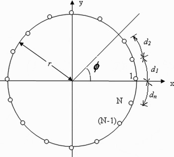
The geometry of an N element circular antenna array has been shown in Fig. 3. The array factor is given by [Reference Balanis1, Reference Shihab, Najjar, Dib and Khodier18]
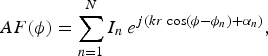
where r is the radius of the circular array and d i is the arc separation as shown in Fig. 3, and
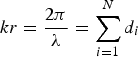
and
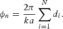
In order to focus the main beam in ϕo direction, the excitation phase of nth element is chosen to be

The following fitness function has been used to evaluate the fitness or cost:

where SLL and BW are the actual sidelobe level (in decibles) and beamwidth (in degrees) of the current design and SLLD is the desired values of sidelobe level, and a and b are the weighting factors, chosen by hit and trail. It has to be mentioned that the above fitness function is different from that of [Reference Shihab, Najjar, Dib and Khodier18] but the design goals are same. This fitness function requires the direct computation of sidelobe level and beamwidth from the pattern obtained using eq. (3) whereas Shihab et al. [Reference Shihab, Najjar, Dib and Khodier18] uses the equation (3) directly in its fitness formulation.
Geometry of a circular antenna array with N isotropic radiators.

The array element amplitudes I n and their separation d i have been taken as variables. The excitation phase values have been directly determined by using equation (4). The stopping criterion used is the maximum number of iterations. The algorithm stops when the current iteration equals the maximum specified iteration.
IV. SIMULATION RESULTS AND DISCUSSION
The fitness function given by equation (5) has been optimized using SA. Constants were set to as a = 60, b = 1. The SA has been run for 60 000 iterations. Initial temperature has been taken as 100 and temperature reduction factor is 0.7. The initial temperature has been taken by observing the number of acceptance at a few temperatures taken. It is taken as the temperature where number of acceptances is 95% [Reference Ruenbar29]. Generally, the initial temperature is kept high and it is gradually lowered. The temperature reduction factor can be kept between 0.7 and 0.9. The stopping criterion used for SA is the maximum number of iterations as in the case of PSO. The algorithm stops when the current iteration equals the maximum specified iteration. Further, it is clarified that by iterations, it means number of objective function evaluations. The amplitude and spacing is allowed to vary between 0.3 and 1 of the respective units.
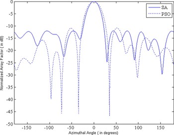
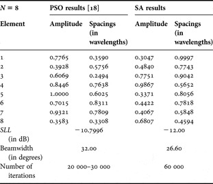
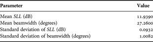
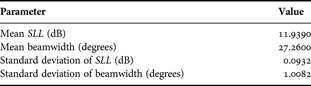
Consider the case of eight element circular antenna array and desired sidelobe level SLLD = −12 dB. Figure 4 shows the radiation pattern obtained. Table 1 shows the comparative results. It can be seen that both the sidelobe level and beamwidth are better in case of SA. The sidelobe level is better by 1.3 dB, whereas beamwidth is better by 6.0° as compared to that obtained using PSO. Also, it can be observed that sidelobe level achieved is exactly same as desired. Further, to check the stochastic validity of the proposed approach, the program has been run for 10 times and performance analysis has been done. Table 2 shows the mean and standard deviation of results obtained. The value of mean and standard deviation are not too high. Thus, it can be concluded that algorithm is well consistent to solve this problem.
Radiation pattern of eight element circular antenna array.

Comparison of best results for eight element circular antenna array.

Performance analysis for 10 simulation runs.
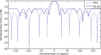
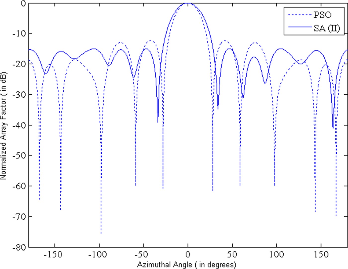
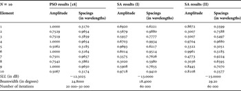
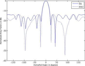
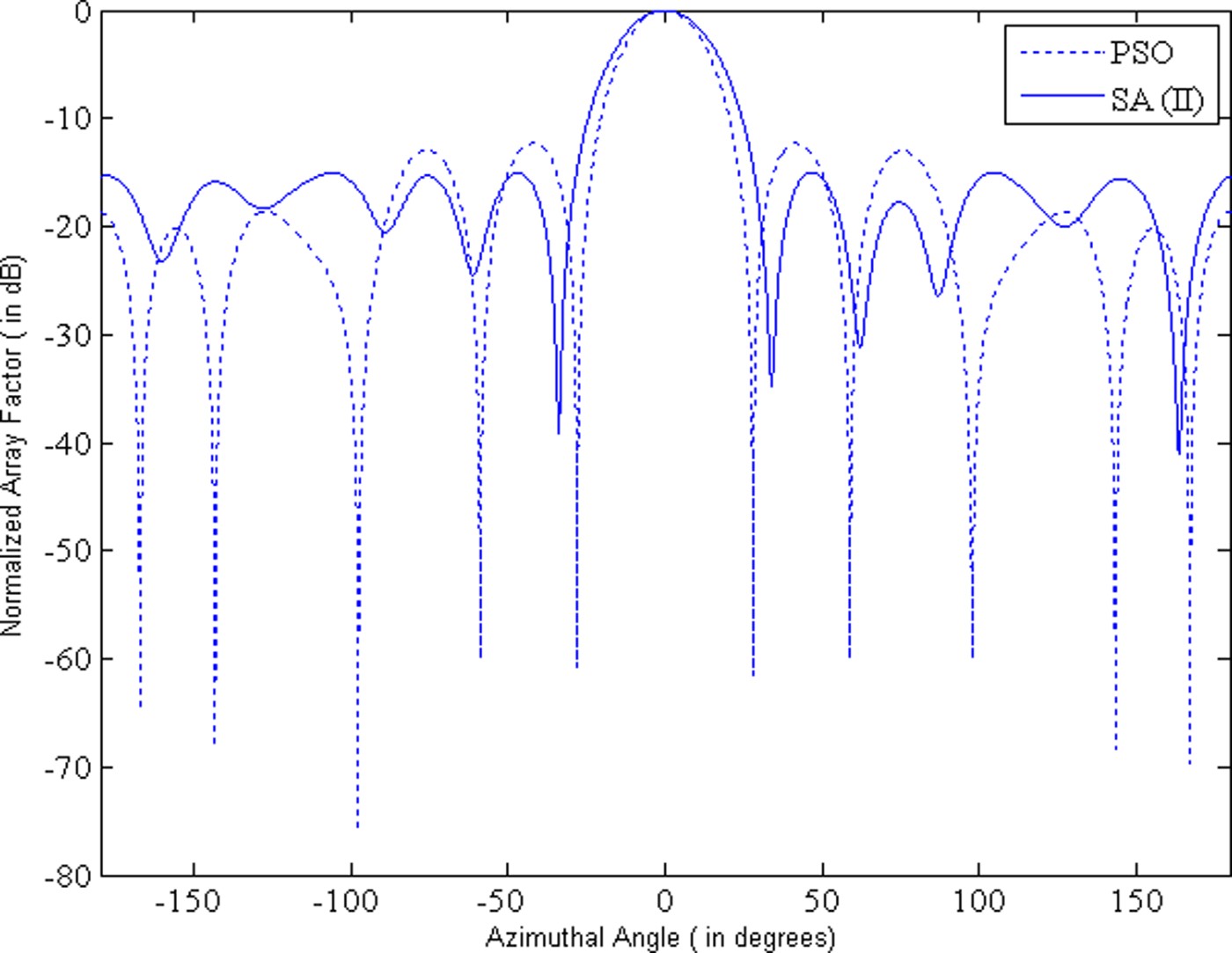
Now, consider the case of 10 element circular antenna array. Constants were set to as a = 60, b = 1, and SLLD = −13 dB. Table 3 shows the comparative results. The sidelobe level is better by 0.7 dB, whereas beamwidth is better by 6.4° as compared to that obtained using PSO. Results have been shown as SA (I). Further, it has to be noted that sidelobe level is exactly matching with the desired value. To observe the trade off between sidelobe level and beamwidth, the value of desired sidelobe level has been changed to −15 dB, keeping other parameters same. The results have been shown as SA (II). Figs 5 and 6 show the radiation pattern obtained for the respective cases SA (I) and SA (II), respectively. It can be seen that beamwidth is increased if improvement in sidelobe level is required.
Radiation pattern of 10 element circular antenna array (Case I).

Radiation pattern of 10 element circular antenna array (Case II).
Comparison of best results for 10 element circular antenna array.

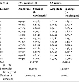
Further, consider the case of 12 element circular antenna array. The desired sidelobe level is SLLD = −14 dB. Figure 7 shows the radiation pattern. Table 4 shows the comparative results. It can be seen that both the sidelobe level and the beamwidth are better in case of SA. Sidelobe level is better by 0.3 dB, whereas beamwidth is better by 1.6° as compared to that obtained using PSO.
Radiation pattern of 12 element circular antenna array.

Comparison of best results for 12 element circular antenna array.

V. CONCLUSION
In this paper, SA has been used to optimize the circular antenna array for the desired value of sidelobe level and the minimum possible value of beamwidth corresponding to that. The position and amplitude variables of each element in the array have been adjusted to obtain the optimum results. The results obtained show improvement over that obtained using PSO algorithm. However, the number of iterations required is more in SA compared to PSO. Future work can be focused on optimization of more complex array geometries and other electromagnetic devices. The practical arrays of anisotropic radiators can also be optimized using this approach. This can be carried out by using the principle of pattern multiplication if mutual coupling effects are to be ignored. A more accurate analysis can be carried out by integrating a Method of Moments (MoM) based software (like NEC2 or IE3D) with Matlab routine.
ACKNOWLEDGEMENTS
We thank the anonymous reviewers for their valuable comments and suggestions that have helped in enhancing the overall quality of the paper.
 Munish Rattan is currently working as Lecturer, in the department of Electronics and Communication Engineering, Guru Nanak Dev Engg. College, Ludhiana. He did his B.Tech. (Electronics and Comm. Engg.) in 2002 from B.B.S.B.E.C. Fathehgarh Sahib, and M.E. (Electronics Engg.) from P.E.C. Chandigarh, in 2004. He has recently submitted his Ph.D. thesis entitled, “Antenna Array Optimization using Evolutionary Approaches” to Punjabi University, Patiala. The work has been done under the guidance of Dr. M.S. Patterh and Dr. B.S. Sohi. He has published several research papers in international and national journals and conferences of repute.
 Dr. Manjeet Singh Patterh did his Bachelor's degree from Madhav Institute of Technology and Science (MITS), Gwalior (MP) and Master's degree from Birla Institute of Technology and Science (BITS), Pilani, both in Electronics Engineering. He did his PhD from Punjab Technical University Jalandhar. He has published several papers in international and national refereed journals and conferences. He is having over 18 years of teaching experience. He is presently working as Professor in department of electronics and communication engineering at UCoE Punjabi University Patiala. His current interests are Digital Signal Processing, Wireless Communication Systems. He is member of IEEE and life member of ISTE, IE(I) and IETE.
 Dr. B.S. Sohi has had his technical education under Panjab University having done his Ph. D. after completing engineering graduation in Electronics and Communication Engineering and postgraduation in Communication Systems from Punjab Engineering College, Chandigarh. He has been in teaching and research for the last 30 years at different levels in various Institutes. Before joining the teaching profession, he has served in Defence Labs and Central Engineering Services. He has published over 50 research papers at national and international levels. His current interests are Digital Signal Processing, Wireless Communication Systems and Digital System Design. He has served as Director, University Institute of Engineering and Technology, Panjab University, Chandigarh. Currently, he is working as Director, Surya School of Engg. and Technology, Patiala.