Introduction
Recently, due to the associated ease in treatment planning and patient set-up, reduced treatment times, and availability of commercial planning systems, many clinics have opted to use the single-isocentre technique to treat multiple lesions. For this reason, it is subject of interest in the medical physics community to determine the radiological, mechanical and dosimetrical accuracy of off-axis targets Reference Gao and Liu1 since it has direct influence on dose degradation. Reference Ahn, Yenice, Koshy, Slavin and Aydogan2–Reference Rojas-López, Díaz Moreno and Venencia4 A recent study of clinical outcomes in patients treated with single-fraction and multi-fraction, single-isocentre, multitarget stereotactic radiosurgery (SRS) to intact and postoperative brain metastases showed that this technique is associated with high local control and acceptable rates of radionecrosis. Reference Palmer, Sebastian and Chu5 Potential advantages in treatment efficiency such as total treatment time have prompted dosimetric feasibility studies finding target conformity comparable to multi-isocentric treatment. Reference Wu, Snyder and Liu6 One of the most important aspects to guarantee the accuracy of this technique is to define a test that measures the mechanical and geometrical precision for targets off-axis, since rotations and translations have a potential effect of degradation on the coverage and delivered dose. Reference Rojas-López, Díaz Moreno and Venencia4,Reference Pudsey, Biasi and Ralston7
The Winston–Lutz (WL) test, Reference Lutz, Winston and Maleki8 originally proposed by Lutz, Winston and Maleki in 1988, is a very popular and well-known test to verify that the radiation isocentre coincides with the mechanical isocentre in a linac-based SRS system. The test was developed to use film, Reference Schell, Bova and Larson9 but it later progressed to an electronic portal imaging device (EPID) measurement that was easy to obtain using commercial software. This had become easily implemented, Reference Rowshanfarzad, Sabet and O’Connor10,Reference Jones, Childress and Kry11 albeit the use of EPID requires the position correction of the portal/acquisition matrix by the motion of the detector with the gantry angle, for example, IsoCal calibration. 12 Nonetheless, the standard WL test focuses solely on machine isocentre; it cannot accurately determine whether the mechanical field centre (located through the light field by the crosshair) and the radiation field centre match when both are off-axis.
The misalignment between mechanical and radiation isocentres can lead to the planned and delivered dose distributions mismatch. Reference Ravindran13 Inaccuracy may occur as a result of factors such as gantry or multileaf collimator (MLC) leaf-bank sag throughout rotation for gravity, Reference Wack, Exner and Wegener14 misalignment of axes, Reference Wack, Exner and Wegener14 linac head imbalance, and wear and tear of bearings. Reference Ravindran13 As often SRS is delivered with multiple non-coplanar arcs, the rotational couch axis alignment must be verified in combination with the gantry and collimator axes. The TG-142 and TG-198 recommend that the tests for positioning or repositioning, imaging and treatment coordinate coincidence for SRS/SBRT machines must be ≤1 mm on the day of SRS treatment hereof. Reference Hanley, Dresser and Simon15,Reference Klein, Hanley and Bayouth16
Many efforts have recently been made to evaluate the off-axis accuracy of the WL test by phantoms in linacs. Reference Gao and Liu1,Reference Pudsey, Biasi and Ralston7,Reference Eagle, Tallhamer and Keener17,Reference Szweda, Graczyk and Radomiak18 One of the most important features to consider is the use of image-guided radiotherapy (IGRT) like cone-beam computed tomography (CBCT) or stereoscopic X-ray imaging, for example ExacTrac™ system (Brainlab AG, Munich, Germany). ExacTrac™ provides faster imaging, Reference Li, Shi and Andrews19 lower dose exposure Reference Ma, Chang and Wang20 and image guidance for non-coplanar treatments. Reference Li, Shi and Andrews19 It is an external system to the linac and therefore requires additional calibration, including the X-ray calibration at the isocentre through the WL test. The use of surface guidance in RT (SGRT) has also been widely implemented for patient positioning, and for linac-based SRS, it could be a surrogate for the position of intracranial treatments. Reference Manger, Paxton, Pawlicki and Kim21 SGRT and IGRT can provide complementary imaging information during patient positioning and throughout treatment, which may improve target localisation.
Our institution carried out an ExacTrac™ version update from v6.0 (ETv6) to Dynamic (ETD) in August 2022, so we acquired the same tests in both versions whose X-rays imaging systems were calibrated and adjusted. In this study, we compare the accuracy of the off-axis WL test for multiple brain metastases (MBM) by the first anthropomorphic phantom in ETv6 and ETD in the same linac. At present, there are commercial and in-house phantoms for this purpose, and the medical physics community has started to quantify the accuracy of off-axis targets. Reference McKenna22,Reference Maurer, Sintay and Varchena23 Nonetheless, this proposal incorporates anatomical information that is more related to the MBM SRS treatments, and we follow a validated method to calculate the 3D displacements. In contrast to the phantoms of preliminary studies that have regular geometric shapes, this phantom simulates the skull of a real patient that was previously treated. In addition, we showed experimentally the effect of rotation on the target displacement. The effect of rotations during the treatment has a considerable dosimetric impact that was quantified in prior research. Reference Nakano, Tanabe and Utsunomiya3,Reference Rojas-López, Díaz Moreno and Venencia4
Methods
We designed a dedicated anthropomorphic phantom to analyse the off-axis displacements by an off-axis WL test and to study the IGRT system’s influence on the older version and the rotational set-up errors.
The tests were delivered using a TrueBeam STx® (Varian Medical Systems, Palo Alto, CA-Brainlab AG, Munchen, Germany) with a high-definition multileaf collimator (HDMLC). The HDMLC HD120® has 120 leaves with 60 central leaf pairs of 2·5 mm width at isocentre. 24 The linac has MV portal imaging, on-board imaging (OBI) system by kV planar imaging, CBCT, ExacTrac™ (Brainlab AG, Munchen, Germany) and a robotic couch top with 6 degrees of freedom (DOF).
The OBI system consists of a kV X-ray source and a flat panel amorphous silicon detector on two retractable arms on the machine’s gantry. A three-dimensional (3D) volumetric CBCT image can be reconstructed from continuous X-ray projections as the gantry rotates around the phantom. Unlike ExacTracTM planar X-ray images, CBCTs provide soft tissue as well as bony contrast and can be registered directly to planning computed tomography (CT) in 6DOF.
Anthropomorphic phantom
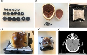
A PseudoPatient® Prime head phantom (RTsafe, Athens, Greece) was used (Figs. 1d and 1e), and a 3D-printed anatomical replica was created using the CT image of a human head. Reference Han, Diagaradjane and Luo25 Nine metallic fiducials (5 mm diameter) were placed on plastic spheric holders (10 mm, 15 mm and 25 mm diameter to differentiate them on the CT images), as shown in Figs. 1a and 1b, and randomly distributed with clinical relevant positions in the phantom (they corresponded with sizes and distances to isocentre reported on average from our institution Reference Rojas-López, Díaz Moreno and Venencia4 ), avoiding overlaps. To ensure that the fiducials do not move during and after the tests, the phantom was completely and carefully filled with silicone. CT images of the immobilised phantom were acquired using a SOMATOM goUp unit (Siemens Healthinners AG, Erlangen, Germany) with the Brainlab stereotactic mask (Figs. 1c and 1f), following the intracranial SRS institutional protocol with slice thickness of 0·6 mm and artefact correction for dental prosthesis.
Anthropomorphic phantom for off-axis WL test. (a) Plastic holders and fiducials. (b) Phantom interior and metallic fiducials and their plastic spherical holders. (c) Frontal view of the phantom with thermoplastic mask. (d) Lateral view. (e) Frontal view. (f) Axial CT image of the phantom.

Assessment of the linac isocentre
Conventional WL test allows us to determine the match between the mechanical and radiation isocentres directly by a radiopaque marker being irradiated. Usually, the irradiated object is a ball-bearing (BB) phantom with a millimetric radius. Reference Yaqoub26 The BB is aligned to the isocentre using the treatment room positioning lasers. The BB is imaged by a circular or square collimated field. The projection of the BB should be in the field in the ideal situation. The good results should show a shift ≤ 0·5 mm. Reference Shepard27
Running the WL test is a time-consuming and tedious process. It could have human errors, such as accidental movement of the couch between beams and selection of inconsistent imaging templates. The automation of the WL test process and analysis shortens the execution test time. The Developer Mode module allows users to access this functionality and operate it through XML scripts. Reference Yaqoub26,Reference Alarcón and Venencia28 The Developer Mode permits access to the full set of capabilities that have been built into the TrueBeam control system, not available in the clinical modes. Reference Yaqoub26 It is driven by XML beams loaded from local storage or network on the TrueBeam control console workstation computer. XML beams are essentially text scripts in XML format where a rich instruction set allows Developer Mode users to construct, deliver and imaging non-standard beams. 29 Therefore, an XML script was used in the development environment of Microsoft Visual Studio Community 2017. Reference Alarcón and Venencia28 The XML contains automation sequences with specific control points, beam configurations and instantaneous image acquisition for each beam. The set of gantry, couch and collimator angles used is chosen based on RIT (Radiological Imaging Technology) software (RadImage, Colorado, USA) requirements and was automatically set up without any need to get into the treatment room between fields.
The EPID must be calibrated by the IsoCal calibration inasmuch as all images are acquired by it. It is an initial adjustment, and it is carried out with some frequency. IsoCal is a licence purchased from Varian. It determines the correct location and alignment between the treatment isocentre and rotation centre of the kV/MV imaging system. 12 Furthermore, the correction for CBCT images is through the IsoCal calibration. Reference Huang, Zhao and Chetty30,31
In our case, we used a WL pointer alignment phantom (Brainlab AG, Munich, Germany). The pointer was imaged by a square collimated field using a set of 16 EPID images with different combinations Reference Clements, Beres and Shastri32 of gantry (0º, 90º, 180º and 270º), collimator (0º, 45º, 135º, 225º, 90º and 270º) and couch (0º, 45º, 90º, 270º and 315º). The test was performed on Developer Mode by automatic execution, and the images were processed on RIT v6.7 to calculate the deviation between radiation and mechanical isocentre using an algorithm Reference Low, Li and Drzymala33 and the projections. Following the WL test, the 3D displacements reported by RIT were used to perform the movements that must be carried out to place the pointer in the isocentre.
Once the optimal position of the pointer is obtained, then we calibrated the X-ray imaging system by the X-ray isocentre adjustment of ExacTracTM. This calibration depends on the initial adjustment of the pointer in the optimum isocentre position. It was performed following Brainlab’s procedures and by the use of the ET isocentre and ET XR calibration phantoms. The calibration of this system is described in Supporting Information.
To show the mechanical error components (gantry, collimator, couch and MLC) of the linac, we performed the gantry/collimator/couch angle indicator test for 0º, 90º, 180º and 270º using a digital spirit level held against the flat reference collimator/couch surface, the star shot test using radiochromic film and the static Picket-Fence tests for 0º, 90º, 180º and 270º using EPID. The images were processed on RIT v6.7.
ExacTrac™
The ExacTracTM X-ray room-mounted imaging system consists of an infrared camera-based tracking system, two kV X-ray tubes recessed into the room floor and two ceiling-mounted amorphous silicon flat panel detectors (512 × 512 pixels). ExacTracTM is a linac-independent system. Therefore, it is essential to calibrate it for the linac isocentre.
ETv6 consists of infrared positioning and set-up system, a video monitoring system, ETv6 control software, a six-dimensional treatment bed, a pair of kV-level X-ray tubes buried underground and two corresponding amorphous silicon flat detectors with a 204 × 204-mm2 radiation-sensitive area. Reference Brainlab34,Reference Hua, Xu and Zhang35 The geometrical radiation field size at the isocentre is 129 × 129 mm2. Its use could be referring to a patient’s anatomy using bone references or fiducials.
Recently, the ETD system, version 1.0 (Brainlab AG, Munich, Germany) was installed in our institution. It is a combined SGRT and IGRT system used for patient positioning, monitoring and tumour targeting. The system can provide intrafractional positioning information of the bony anatomy via oblique stereoscopic X-ray imaging of the patient in parallel to real-time 3D surface imaging, including thermal information, for continuous motion detection during treatment delivery. Reference Shepard27,36 In contrast to other systems, only one optical camera is used by structured light scanning, but thermal information creates an additional dimension, which is assumed to improve tracking accuracy. Reference Da Silva Mendes, Reiner and Huang37
Off-Axis WL test
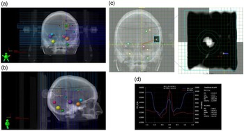
The CT images were imported on Eclipse v15.6 (Varian Medical Systems, Palo Alto, CA, USA). The targets (fiducial + plastic holder) were carefully contoured keeping their spherical shape. Each target was designed an off-axis WL test with eight different gantry/collimator/couch combinations, as shown in Table 1. The 2·6 × 2·6 cm2 square field was defined by the MLC, and primary jaws were fixed to define a 3 × 3 cm2 square field as shown in Figs. 2a, 2b. The centre of the square field is the fiducial. The isocentre was set in the mass centre of the nine targets.
Gantry, couch and collimator angle combinations at which images of the targets were obtained

Off-axis WL test. (a) Beam eye view (BEV) for the combination collimator 0º, gantry 0º and couch 0º with an MLC square field of 2·6 × 2·6 cm2 and jaw field of 3 × 3 cm2 and (b) BEV for the combination collimator 90º, gantry 90º and couch 0º. (c) Offline review of the image acquired and the DRR. The isocentre is defined in the intersection point of the yellow orthogonal axis. (d) Horizontal profile extracted from (c).

Before performing the tests, phantom pre-positioning was done using the ExacTrac™ systems at the couch 0º position. To position with the optical surface camera, it was mandatory to select an area to track with temperature for thermal 3D information registration by the Perspective-n-Point algorithm. 38 Subsequently, it is necessary to correct the position with X-rays at each couch angle. The phantom used the frameless SRS positioning array with infrared spheres and the surface for ETv6 and ETD, respectively. Then, the final position was taken by stereoscopic X-ray images with tolerances of 0·5º/0·5 mm. These tolerances are defined at isocentre, and they are considered as clinical consensus Reference Meeks, Mercado and Popple39,Reference Calmels, Blak Nyrup Biancardo and Sibolt40 for intrafraction uncertainties during single-fraction MBM SRS treatments. Moreover, these are the movements that ExacTracTM and the robotic couch can correct during the treatment. CBCTs were acquired at couch 0º position, as a second check for pre-positioning and at the final of the test, and registered to the planning CT, confirming that the displacements were in tolerance.
Portal images were acquired for all gantry and couch angles as described in Table 1. In the cases where the couch was moved, the couch’s position was verified through stereoscopic X-rays. If the imaged position is out of tolerance in any gantry–couch combination, 6D shifts were applied and the phantom was reimaged until the residual shifts are within tolerance.
The 2D deviation between the fiducial centre and the radiation field centre, for each projection image, was found by off-line review, and comparison with the original digital reconstructed radiography (DRR) by the horizontal and vertical profiles (Figs. 2c and 2d) was done. The deviations were compared with the values reported by the toolkit QALMA. Reference Rahman, Lei and Kalantzis41
Using a formal reported method, Reference Low, Li and Drzymala33 the optimal fiducial displacement from the current location in three dimensions (generally labelled dX, dY and dZ) was found that would minimise the vertical and horizontal deviations (x and y) at the projected locations. If we consider the deviations (x and y) in the gantry coordinate system where the gantry has been rotated to an angle of θ and φ defines the couch rotation angle, then it is possible to relate the deviations with the vertical (V), lateral (L) and anterior-posterior (AP) shifts as:
 $$\matrix{ {\left( {\matrix{ x \hfill \cr y \hfill \cr } } \right) = \;\left( {\matrix{ {vertical} \cr {horizontal} \cr } } \right)} \hfill \cr {\quad \quad \;\;\; = \left( {\matrix{
{\cos \varphi } & { - \sin \varphi } & 0 \cr {\cos \theta \sin \varphi } & {\cos \theta \cos \varphi } & {\sin \theta } \cr } } \right)\left( {\matrix{ V \cr L \cr {AP} \cr
} } \right)} \hfill \cr {\quad \quad \;\;\; = A\left( {\theta ,\varphi } \right) \times \Delta .} \hfill \cr } $$
where A(θ, φ) is the 2 × 3 matrix above and Δ is the shift vector (dX, dY and dZ). For n combinations of gantry/collimator/couch, if
 $\eta = \left( {\matrix{ {A\left( {{\theta _1},\;{\varphi _1}} \right)} \cr \vdots \cr {A\left( {{\theta _n},\;{\varphi _n}} \right)} \cr } } \right)\;$
and
 $\xi = {\left( {{x_1},\;{y_1},\; \cdots ,{x_n},\;{y_n}} \right)^T},\;$
there is a unique solution that minimises Δ:
 $$\Delta = \;\left( {{{\left( {{\eta ^T}\eta } \right)}^{ - 1}}{\eta ^T}} \right)\xi .$$
The maximum 3D displacement was obtained following an isocentre optimisation. Reference Clements, Beres and Shastri32,Reference Low, Li and Drzymala33 The details are described in RIT documentation.
-
(a) To convert 2D (x,y) into 3D (x’, y’, z’) deviations for gantry/collimator/couch combinations by polar transformation (non-rotated coordinate system).
-
(b) The gantry rotation isocentre point, P, is chosen as the midpoint of the extremes in each projection axis. This location was chosen because it minimises the maximum deviation at any point in space:
(3) $$P = \;\left( {\matrix{ {{P_x}} \cr {{P_y}} \cr {{P_z}} \cr } } \right) = \left( {\matrix{ {{\raise0.7ex\hbox{${\left( {\max x' + \min x'} \right)}$} \!\mathord{\left/ {\vphantom {{\left( {\max x' + \min x'} \right)} 2}}\right.}\!\lower0.7ex\hbox{$2$}}} \cr {{\raise0.7ex\hbox{${\left( {\max y' + \min y'} \right)}$} \!\mathord{\left/ {\vphantom {{\left( {\max y' + \min y'} \right)} 2}}\right.}\!\lower0.7ex\hbox{$2$}}} \cr {{\raise0.7ex\hbox{${\left( {\max z' + \min z'} \right)}$} \!\mathord{\left/ {\vphantom {{\left( {\max z' + \min z'} \right)} 2}}\right.}\!\lower0.7ex\hbox{$2$}}} \cr } } \right)\;$$
-
(c) To take the differences between the gantry rotation isocentre point and each deviation.
-
(d) The effects of the gantry, collimator, and couch rotation have been minimised, and calculations of the deviations between beam centre and fiducial for all possible rotations can be determined and reported. The maximum deviation given all possible combinations can then be reported following (c).

The CBCT images were co-registered with the planning CT. The deviations with the vertical, lateral and AP shifts were measured, and the 3D displacement was calculated as the Euclidean distance.
The 3D displacements calculated between the two versions of ExacTracTM were compared by the use of Mann–Whitney–Wilcoxon test in Python v.3.11 with significance level of α = 0·05.
Finally, rotational errors of 0·5º were induced in the three directions (roll, pitch or yaw) and the off-axis WL tests were taken and analysed.
Results
The tests for the assessment of the linac isocentre for mechanical rotational axes were analysed. The average variation in couch angle was (0·06 ± 0·05)º. The average collimator variation was (0·00 ± 0·10)º, and the gantry angle variation was (0·05 ± 0·05)º. In terms of star shot results, the minimum tangent circle radius described for the collimator was 0·15 mm, for the couch was 0·20 mm, and for the gantry was 0·31 mm. In terms of Picket-Fence results, the maximum variation for 0º was 0·12 mm, for 90º was −0·17 mm, for 180º was −0·20 mm and for 270º was −0·14 mm. By the IsoCal calibration, the maximum deviation from the central beam was 0·36 mm, and the MV/kV detector rotation and its maximum shift were −0·089º/0·11 mm for MV and 0·023º/0·06 mm for kV. The ETD installation did not affect the IsoCal calibration.
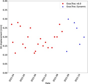
Figure 3 shows the follow-up for 7 months of the 3D displacements. In this figure, it is noticeable that no changes were found after the installation of ETD. The average displacement for 7 months was (0·19 ± 0·05) mm.
Seven months follow-up of the 3D displacements obtained by WL test at isocentre with the ExacTrac™ v6.0 (red circles) and ExacTrac Dynamic™ (blue triangles).

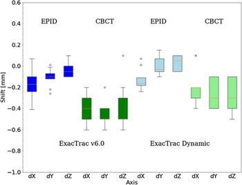
A set of eight EPID images for the off-axis WL test for each of the nine targets was acquired. Full data are presented in Supporting Information, where we showed data consistency for each gantry/collimator/couch combination. Figure 4 shows the EPID and CBCT shifts produced after the verification and correction by IGRT using both ExacTrac™ versions. The shifts between pre-positioning and at the final of the test CBCTs were evaluated, and no differences were obtained (data not shown). In all cases, there was statistical significance for EPID and CBCT (p < 0·001). In terms of the shifts, the relative differences between QALMA results and the method proposed in this study were up to 3% (data not shown). The variations were attributed to the different mathematical-computational methods to determine the 2D and 3D deviations.
Comparison of the shifts in both ExacTrac™ (v6.0 and Dynamic) obtained by CBCT and EPID by the off-axis WL test for the nine targets.

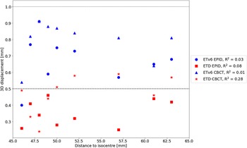
Figure 5 shows the 3D displacements for EPID and CBCT after the verification and correction by IGRT using both ExacTracTM systems. In Fig. 5, it is shown that 3D displacements obtained by ETD are smaller than those produced with ETv6. It is noticeable that by the use of EPID and CBCT, these displacements were reduced by almost half and there was statistical significance for EPID and CBCT. In Fig. 5, it is presented that 3D displacement does not have noticeable correlation concerning the distance to isocentre (R 2 ≪ 0·3).
3D displacements obtained for both ExacTrac™ (ETv6 and ETD) obtained by CBCT and EPID. Horizontal lines represent the maximum tolerance allowed (1 mm) and IGRT for SRS intrafraction tolerance (0·5 mm).

Finally, Table 2 shows that 3D displacements slightly vary with the rotational displacement-induced error. Quantitatively, for 0·5º errors, the mean displacement is close to 1 mm. Moreover, the displacement varies with the rotational axis.
Mean displacements by applying rotations in both IGRT systems using EPID

Discussion
The IGRT system is relevant to the patient positioning on SRS for MBM, especially if the treatment modality is based on a single isocentre. ExacTracTM system is a good option, and the positioning is equivalent up to 0·4 mm to CBCT as presented in other work. Reference Da Silva Mendes, Reiner and Huang37 The advent of the new version (ETD) uses optical/thermal and stereoscopic X-ray imaging information for the positioning, the fusion algorithm and the image quality promise to have improvements in accuracy. Reference Freislederer, Kügele and Öllers42 Thus, there is a need to evaluate and compare this characteristic with older versions of ExacTracTM. In particular, to our knowledge, this is the first comparative study of two versions of this system in the same linac. The results showed acceptable values in both cases, considering 3D displacement tolerances of 1 mm for targets up to 65 mm from the isocentre. These values were reached with rigorous quality assurance (QA) linac tests performed routinely that include mechanical, MV/kV and IGRT tests as recommended by the TG-142.
The global uncertainty introduced by the gantry, collimator and couch, taken as a squared sum, is 0·4 mm. We verified the patient set-up further with IGRT and confirmed that the spatial-mechanical accuracy was consistently maintained at distances away from the isocentre for all targets with our set-up using an anthropomorphic phantom. Nevertheless, ETD allows an accuracy of 0·2 mm at the isocentre and indicated more accurate values Reference Klein, Hanley and Bayouth16 (<0·5 mm) for the targets up to 65 mm from the isocentre. This result provides remarkable information to account for gross target volume - planning target volume (GTV-PTV) margin expansion to reduce the dosimetric risk in healthy tissue while preserving dose coverage. In contrast, for targets 50 mm from the isocentre, Gao et al. reported deviations up to 2 mm and 4·5 mm considering the field defined by MLC and jaws, respectively. Reference Gao and Liu1 The differences with that investigation could probably be attributed to IGRT correction at each couch configuration change during intrafraction movements.
Earlier studies showed no clinical impact on the maximum, mean dose and D95 to the targets for 0·5º rotations, Reference Rojas-López, Díaz Moreno and Venencia4,Reference Prentou, Pappas and Logothetis43 but conformity and gradient indices could be degraded up to 50%. To prevent this, it is necessary to adjust the margins in a smart way considering the mechanical, geometrical and dosimetric uncertainty of the whole treatment process. We will study in future work the optimisation of all the sources of uncertainty in the PTV margin assessment. Nevertheless, we advent that the reduction of the uncertainty values can increment the risk of radionecrosis. Therefore, as mentioned in other work, it is essential to treat the MBM with smaller treatment margins, which requires a 6-DOF correction under the guidance of on-board CBCT, additional equipment such as the ExacTracTM and a thermoplastic mask. Reference Freislederer, Kügele and Öllers42 Furthermore, it is necessary to establish limits that can be reached in the clinical routine that ensure a correct delivery of the treatment without increasing the treatment time or inducing problems in its delivery. The difference found in this work for both ExacTrac systems allows this.
Although there are studies using different phantoms for off-axis WL tests, it is necessary to evaluate the impact of potential mismatch of IGRT systems using anthropomorphic phantoms on patient set-up. On the one hand, the method proposed in past research is based on a first approximation and modification of the WL test using the same phantom to perform the conventional WL test. Reference Gao and Liu1 However, they use the Euclidean distance metric to calculate the deviations, without considering the combination of the collimator, gantry, and couch angles, and the displacements were made in a single axis and do not specify the axis studied. Also, it did not specify the used version of ExacTracTM, which is relevant, as mentioned in this paper. Reference Gao and Liu1 On the other hand, in terms of displacements produced after the IGRT correction, the results of this work are in agreement with the one reported, Reference Pudsey, Biasi and Ralston7 but they did not present which IGRT system used (<1 mm).
Furthermore, by the use of IGRT (CBCT or EPID), for distances to isocentre between 40 and 65 mm, we reported that the correlation between this parameter and the 3D displacement is negligible. Most modern SRS set-up now employs image guidance that strives to minimise positioning error within the region of interest for the kV image versus DRR fusion regardless of isocentre position. The earlier analysis included an experimental validation using a polystyrene phantom for ExacTrac™/PerfectPitch showing that IGRT positioning accuracy (0·4 mm) has no relation with the distance to isocentre. Reference Ahn, Yenice, Koshy, Slavin and Aydogan2 In this work, the corrections by IGRT allowed to remain the displacements lower than 1 mm using both ExacTracTM systems by EPID and CBCT. Nevertheless, the results showed that ETD improved accuracy.
The 2017 AAPM-RSS practice guidelines for SRS/SBRT Reference Halvorsen, Cirino and Das44 undergo thorough consensus processes and extensive review to develop minimum standards for safe practice. However, these guidelines do not include policy or standard operating procedures for departments; therefore, specific procedures must be assessed per department. Reference Pudsey, Biasi and Ralston7 Thus, additional tests for off-axis targets can add information to establish sufficient margin expansion for each lesion. The experimental results are relevant to well identify all the possible sources of uncertainty, since computational studies Reference Chang45,Reference Kang, Chai and Jeong46 do not consider the potential impact of MLC accuracy, rotational movements of the gantry, collimator, and couch, the lasers positions, the mechanical/radiation isocentre match and so on.
In this study, it was shown that the off-axis WL test with an anthropomorphic phantom is sensitive to rotational errors. The impact of these errors has to be measured and well established for each target to define correct security margins to prevent dose degradation. The systematic increment of rotational error for both ExacTracTM systems applying 0·5º movements in roll, pitch and yaw is in agreement with values reported in another work. Reference Pudsey, Biasi and Ralston7 In addition, a statistical model shows that for 0·5º rotations in a target 60 mm from the isocentre, the rotational uncertainty is up to 0·6 mm. Reference Halvorsen, Cirino and Das44 Adding this uncertainty to our global uncertainty, the 3D displacement obtained for ETD is consistent with the values reported in Table 2. Moreover, it is evident that the direction in which a rotation is applied impacts the final displacement of the target. A study in a lucite cubic phantom showed similar results applying cumulative 0·5º roll and pitch rotations for a target 52 mm from the isocentre with 3D displacements of 1·1 mm. Reference Tominaga, Araki and Shimohigashi47
Another important feature is the size and volume of the target. We evaluate the displacements on spherical targets, where their mass centres are in the centre of each sphere. However, in many cases, clinical targets are not spherical, producing that the mass centres could be distributed along a particular axis (major axis if it is ellipsoidal). Thus, the displacement is relevant in a specific axis, and it can produce movements dependent on the rotation direction.
Limitations
The formal method of 3D displacement calculation Reference Low, Li and Drzymala33 does not account for collimator rotation. Since linac-based SRS/SBRT is heavily weighted towards MLC-defined treatment fields, this cannot be considered irrelevant. The simple comparison of individual deviations at the various collimator rotation angles to threshold criteria for whether or not the deviation was acceptable for treatment can not only lead to a misleading definition of isocentre accuracy but also significantly affect treatments where margins are intended to be very small.
For that reason, the 3D displacement is a more reliable metric, since the 3D location in space minimises the maximum deviation at any gantry, collimator, and couch rotation angle, and it is possible to characterise the individual deviations at any angle for isocentre location.
This study does not consider targets with distances to the isocentre farther than 65 mm. Neither was evaluated the relative angle between the linac coordinate system and the relative coordinate system of each target. The relative positions could be related to the fact that the displacements produced for a target in each direction are not equal.
Conclusion
We consider that MBM SRS patient positioning by ExacTracTM system is the benchmark. The new features such as the use of optical/thermal and stereoscopic X-ray imaging information, the fusion algorithm and the image quality performed by ExacTrac DynamicTM allow more accurate definition of the displacements for off-axis targets than its version v6.0, showing 3D displacements up to 0·5 mm in all targets no matter the distance to isocentre. When comparing the displacements produced by rotational errors, it is evident that with rotations from 0·5º, displacements from 1 mm are reached.
Supplementary material
The supplementary material for this article can be found at https://doi.org/10.1017/S1460396923000274.
Competing interests
The authors have no relevant conflicts of interest to disclose.