1. INTRODUCTION
Spatial grammars are rule-based, generative, and visual formalisms for the specification of spatial languages. Spatial grammars include set grammars, graph grammars, shape grammars, and other kinds of grammars for describing spatial languages. This “uniform treatment” of grammars is introduced in the work of Krishnamurti and Stouffs (Reference Krishnamurti and Stouffs1993), and also used in later work of Hoisl and Shea (Reference Hoisl and Shea2011) and McKay et al. (Reference McKay, Chase, Shea and Chau2012). The potential of shape grammars (a specific kind of spatial grammar) as a theoretical framework for analyzing and generating (architectural) designs has been demonstrated through a broad range of formal studies (Stiny, Reference Stiny1977; Koning & Eizenberg, Reference Koning and Eizenberg1981; Flemming, Reference Flemming1987; Duarte, Reference Duarte2005). However, many existing grammars in architectural design (and other design disciplines) are developed on paper, and relatively few grammars have been implemented computationally thus far. Some exceptions can be found, including the work of Aksamija et al. (Reference Aksamija, Yue, Kim, Grobler and Krishnamurti2010), Granadeiro et al. (Reference Granadeiro, Duarte, Correia and Leal2013), and Grasl (Reference Grasl2012). Nevertheless, the computer implementation of shape grammars remains an open research question, because there seems to be no definite answer in the literature on how shape grammars can be implemented to a computer system. For example, a recent overview of McKay et al. (Reference McKay, Chase, Shea and Chau2012) summarizes the key limitations, benefits, and open challenges of the main representative shape grammar implementations to date. The question how to implement shape grammars is also an important research question, because computer implementations are beneficial in many cases, including to automate several aspects of design analysis and generation (especially for grammars that are too extensive to explore manually), to learn from the computer implementation about the design of the shape grammar itself, and to extend the impact of shape grammars toward design practice and computer-aided design (CAD) tools by providing tools to apply shape grammars in practice.
In this paper, we describe a method for the implementation of a shape grammar, originally developed on paper, on a computer system using a graph-theoretic representation of this grammar. We start from a literature review of previous research efforts in which spatial grammars are implemented to a computer system (Section 2). In particular, the definition and characteristics of different kinds of spatial grammars are compared, thereby focusing on shape grammars because they are often used for analyzing and synthesizing architectural and creative designs. In addition, an overview of previous shape grammar implementation approaches is given. Next, we describe the research method, in which we point out a practical step-by-step approach for the computer implementation of shape grammars (Section 3). In the following section (Section 4), the proposed approach is evaluated through the implementation of the Rabo-de-Bacalhau (RdB) transformation grammar, originally developed by Eloy (Reference Eloy2012). In particular, three relevant types of rules that are used in the RdB transformation grammar are implemented: (1) assignment rules, (2) rules to connect spaces by eliminating walls, and (3) rules to divide spaces by adding walls. A discussion of several issues encountered during the implementation and an evaluation of the proposed approach is given in Section 5. Finally, conclusions and future research are described in Section 6.
The work presented in this paper contributes to the current state of the art in shape grammar implementations in several ways. First and foremost, a practical step-by-step approach is presented for the computer implementation of a shape grammar. While the proposed approach builds further on existing research on the graph-theoretic representation of shapes, such as recent work of Grasl (Reference Grasl2013) and Wortmann (Reference Wortmann2013), the proposed approach is also different because it can be applied in different contexts, ranging from simple shape grammars to more complex grammars. Second, the implementation of the RdB transformation grammar (Eloy, Reference Eloy2012) is in itself a useful contribution, because it demonstrates how shape grammar implementations can also be used in more complex (architectural) design situations. In most papers on shape grammar implementations, the approach is validated through a rather straightforward “showcase” grammar, while the RdB transformation grammar is more complex due to the parallel representation of designs, rule conditions, and so forth. However, it is also an example of a grammar that can be used in architectural design practice. One of the most common criticisms to shape grammars is that there is little evidence of their use in practice, so the implemented RdB transformation grammar serves as an example application in architectural design practice, in particular, the development of a (semi)automated methodology for supporting mass housing refurbishment. Third, the case study of implementing the existing RdB transformation grammar reveals several findings on how grammar designers can learn from the implementation about the design of the original grammar, and about the implications on the original grammar itself. Fourth, the proposed approach is embedded within a commercial CAD environment to make the shape grammar formalism more accessible to students and practitioners (architects and product designers), and therefore it might increase the impact of shape grammars on design practice.
2. RELATED WORK
In this section, we compare the definition and characteristics of different kinds of spatial grammars. In particular, we focus on shape grammars because they are often used for analyzing and synthesizing architectural and creative designs. We also provide a literature review of previous research efforts in which a graph formalism is used for shape grammar implementations.
2.1. Spatial grammars
Grammars in general are formal mathematical structures for specifying languages. All different kinds of grammars (string grammars, shape grammars, graph grammars, and set grammars) share certain definitions and characteristics (Krishnamurti & Stouffs, Reference Krishnamurti and Stouffs1993). In particular, a grammar is defined as a four-tuple (N, T, R, I) where N is a finite set of nonterminal entities; T is a finite set of terminal entities; R is a finite set of rewriting rules or productions; and I is an initial entity, a subset of N ∪ T.
A rewriting rule (or production) has the form left-hand side → right-hand side and can be considered as an IF–THEN statement. The left-hand side contains entities from T and N, but cannot be empty. The right-hand side also contains entities from T and N, but can be empty. A rule can be applied if the left-hand side of the rule matches a part of the given object, under a certain transformation (f). If this is the case, the matching part of the given object is replaced by the right-hand side of the rule, under the same transformation f. As a result, a grammar defines a language that contains all objects generated by this grammar.
Spatial grammars, in particular, are specific kinds of grammars that operate on objects in a Euclidean space E 2 (for two-dimensional objects) or E 3 (for three-dimensional objects). Krishnamurti and Stouffs (Reference Krishnamurti and Stouffs1993) describe four kinds of grammars that can serve as spatial grammars: string grammars, set grammars, graph grammars, and shape grammars. String grammars deal with a single string of symbols, in which each symbol corresponds to a geometrical entity represented as a graphical icon. Set grammars deal with spatial objects that are described as sets of geometrical entities. For example, three-dimensional solids can be represented as collections of faces, edges, and vertices. An example that combines string and set grammars can be found in the work of Woodbury et al. (Reference Woodbury, Radford, Taplin and Coppins1992). Graph grammars deal with a set of entities (nodes) where some pairs of entities are connected by links (edges). A common characteristic of string grammars, set grammars, and graph grammars is that spatial objects are represented using symbolic entities: strings, sets, and graphs, respectively.
Unlike other spatial grammars, shape grammars operate directly on spatial objects (shapes), rather than through symbolic entities (Stiny, Reference Stiny2006). A powerful feature of shape grammars is that shapes and their properties can be reinterpreted continuously during the process of rule application, allowing emergence of shape features or properties that are not apparent in the initial definition of the shapes (Knight, Reference Knight2003). In shape grammar theory, algebras are used to represent shapes. An algebra Uij consists of a set of geometrical shapes defined in dimension i = 0, 1, 2, or 3, which are points, lines, planes, and solids, respectively. These shapes are combined in a dimension j ≥ i. Labels and weights are also introduced to define new algebras Vij and Wij (Stiny, Reference Stiny1991).
In the architectural design domain, shape grammars are often used for analyzing and generating creative designs (Stiny, Reference Stiny1977; Koning & Eizenberg, Reference Koning and Eizenberg1981; Flemming, Reference Flemming1987; Duarte, Reference Duarte2005). Relatively few such shape grammars have been implemented to a computer system, with some exceptions available (Aksamija et al., Reference Aksamija, Yue, Kim, Grobler and Krishnamurti2010; Grasl, Reference Grasl2012; Granadeiro et al., Reference Granadeiro, Duarte, Correia and Leal2013). Typically, the user of such unimplemented shape grammars is meant to interpret the grammar and manually apply the rules in order to generate designs (see the work of Chase, Reference Chase2002, for an overview of interaction strategies with shape grammars). In contrast, for computer implementations of shape grammars, the computer system should automatically determine where and how rules are to be applied. While human designers are extremely good at recognizing possible rule applications and readily make meaning from visual fragments, there is general agreement that the ability of computer systems for shape recognition and interpretation is below human capacities. For example, Jowers et al. (Reference Jowers, Hogg, McKay and de Pennington2010) have successfully applied automatic object recognition techniques (in particular, a method called Hausdorff distance) to interpret shapes without an underlying representation. However, this implementation is also limited; for example, it may not be able to identify spaces in a floor plan, while a (trained) human person can almost immediately detect different spaces by just looking at the floor plan. While computer systems often rely on predefined representations in order to interpret given information, shape grammars rely on emergence and continuously changing representations, thus making them not particularly amenable for computer implementation. Even for shape grammars that do not support emergence, the detection of applicable rules is a complex task to solve for computers, such as finding subshapes for rule application (Krishnamurti, Reference Krishnamurti1981).
A large spectrum of shape grammar types can be identified (Knight, Reference Knight1999; Yue & Krishnamurti, Reference Yue and Krishnamurti2014), including subshape-driven versus label-driven shape grammars, nonparametric versus parametric shape grammars, rectilinear versus curvilinear shape grammars, and shape grammars with or without emergence enabled. As Yue and Krishnamurti (Reference Yue and Krishnamurti2014) point out, the complexity and choice of the implementation approach depends on the type of shape grammar to be implemented. In this paper, we propose an implementation approach that consists of translating a shape grammar to a graph-theoretic equivalent grammar. Graphs provide an elegant way to describe topological compositions and incidence relations of spatial objects, but can also account for geometrical properties by associating attributes to the graph objects. Moreover, practical solutions and algorithms for (sub)graph matching and automatic rule application exist in the literature (Taentzer, Reference Taentzer2004; Geiß et al., Reference Geiß, Batz, Grund, Hack and Szalkowski2006). This graph-based approach is applicable for shape grammars that are either subshape driven or label driven and support parametric shapes. Another important benefit of using such a graph-based implementation approach is that shape grammars can also be implemented with emergence enabled. A short discussion of this can be found in Section 3.1 and other research work of Grasl (Reference Grasl2013) and Wortmann (Reference Wortmann2013); however, enabling emergence is not the main topic of this paper. An aspect that is not considered in this paper is how to support curvilinear shapes, but a good discussion of this can be found in the work of Jowers and Earl (Reference Jowers and Earl2011). An overview of existing shape grammar implementations, including graph-based approaches and other approaches, is presented in the following section.
2.2. Previous implementation approaches
The implementation of shape grammars has been the subject of many research efforts since the original conception of shape grammars in the 1970s (Stiny & Gips, Reference Stiny, Gips and Freiman1971). The dilemma, addressed by Gips (Reference Gips1999), is the tension between the visual nature of shape grammars and the inherently symbolic nature of computer representations and processing. An overview of more recent research efforts is given in the work of Gips (Reference Gips1999; Chase, Reference Chase2010). Chase (Reference Chase2010) summarizes the main representative shape grammar implementation systems (Li et al., Reference Li, I-Kang, Chau and Chen2009; Correia et al., Reference Correia, Duarte and Leitao2010; Ertelt & Shea, Reference Ertelt and Shea2010; Hoisl & Shea, Reference Hoisl and Shea2011; Jowers & Earl, Reference Jowers and Earl2011; Trescak et al., Reference Trescak, Esteva and Rodriguez2012). These systems are analyzed and compared in terms of form, semantics, definition interface, and generative capabilities. McKay et al. (Reference McKay, Chase, Shea and Chau2012) analyze these systems according to four characteristics: representation and algorithms, user interaction and interface, support for particular problems, and support for specific stages of the development process. Currently available implementations, although still prototypes and each focusing on just a few particular aspects, have made valuable contributions on enabling subshape recognition, emergence, parametric rules, and curvilinear shapes, and present more user friendly interfaces and flexible representation processes.
A fundamentally different approach toward shape grammar implementation is the use of graphs as an underlying framework for representing shapes. Graphs are data structures that represent a set of entities (nodes) where some pairs of entities are connected by links (edges). Graphs offer a natural framework to model spatial entities (solids, faces, edges, and vertices) and the relations between these entities. The use of graphs to represent spatial shapes or designs is not uncommon in the architectural design domain. For example, Fitzhorn (Reference Fitzhorn1990) uses graphs to represent three-dimensional solids, and Steadman (Reference Steadman and March1976) describes a graph-theoretic representation of architectural arrangements. If graphs are used to represent shapes or designs, graph rewriting systems can be used to create new graphs out of an original graph, similarly to how it occurs for shape grammars. Graph grammars are used for divergent purposes, but they can also be used to develop formal languages of spatial objects. Among the first attempts to describe such formal languages is the approach of Fitzhorn (Reference Fitzhorn1990). In this approach, a graph grammar is defined to generate boundary representations of three-dimensional solids. These solids are defined as sets of geometrical entities (solid, face, edge, and vertex) and their corresponding topological relations. The production rules of the grammar are defined as Euler operators in order to generate solids that are syntactically correct. This approach was adopted and extended in the work of Heisserman (Reference Heisserman1994). In this approach, three-dimensional solids are represented as labeled boundary graphs, and boundary solid grammars are used to develop spatial languages. Other examples include the work of Shea and Cagan (Reference Shea and Cagan1999), in which graphlike shapes are applied to produce structural forms, and the work of Helms and Shea (Reference Helms and Shea2012) on representing designs as graphs. In other recent work, it has been demonstrated how graph grammars can also represent parametric shape grammars, and how emergence, a foundational feature of shape grammars, can be supported (Grasl, Reference Grasl2013; Wortmann, Reference Wortmann2013). In the recent work of Grasl and Economou (Reference Grasl and Economou2013), a graph-based shape grammar library called GRAPE is proposed that provides a general framework for graph-based shape grammar implementations.
In conclusion, several shape grammar implementation systems are available, each having a specific focus and purpose. The shared focus of these systems is to allow designers or shape grammar users to implement their shape grammar on a computer system. Still, computer implementations of complex shape grammars are seldom. An interesting counterexample can be found in the work of Grasl (Reference Grasl2012), in which a graph-theoretic equivalent of the Palladian shape grammar is described that can generate the same language of Palladian villas as the original shape grammar introduced by Stiny and Mitchell (Reference Stiny and Mitchell1978). In the next section, an approach for the implementation of shape grammars is proposed that builds further on existing research on the graph-theoretic representation of shapes and shape grammars (Grasl, Reference Grasl2013; Wortmann, Reference Wortmann2013), but it is also more general than previous approaches, and it can be applied in different contexts.
3. METHOD: IMPLEMENTING A SHAPE GRAMMAR
In order to translate a shape grammar, specified on paper, to a computer-amenable and graph-theoretic grammar, several steps are needed. In this section, a step-by-step approach is given to define a graph-theoretic representation of the shape grammar to be implemented.
3.1. Step 1: Defining the ontology
The first step in the proposed translation of a shape grammar to a graph-theoretic grammar is to construct an ontology that defines the node types, node properties, and relations between the nodes. A graph is a mathematical structure that represents relations between nodes. Therefore, the node types that are used and the possible relations between different node types of the graph-theoretic grammar must be defined. In other words, this corresponds to defining an ontology beforehand, which allows computers to more easily interpret given visual information in terms of this predefined ontology. The predefined ontology should describe the different entities considered and how they relate to other entities (spaces, walls, edges, vertices, and other kinds of geometric, semantical, or spatial entities). This ontology determines what information can be expressed in the computerized grammar and how this information will be interpreted by the computer system. The definition of an ontology depends on the given shape grammar and on the envisioned functionality of the grammar implementation; for example, if the given shape grammar concerns only two-dimensional shapes, the ontology needed is more limited than for shape grammars that operate with more complex semantic entities (such as walls, spaces, and other architectural concepts).
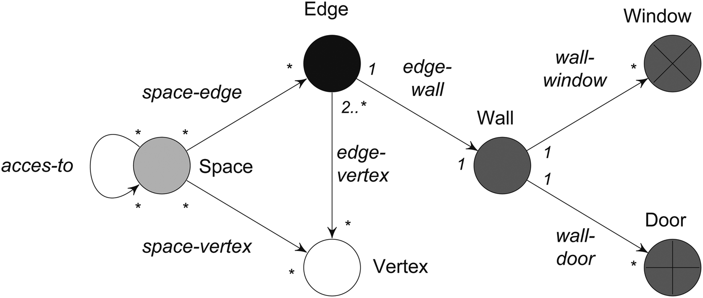
As an example, an ontology with six different node types is considered: vertex, edge, space, wall, door, and window. With such an ontology, the computer system is able to recognize both geometrical entities (vertex and edge) and nongeometrical entities (space, wall, door, and window. In addition, seven different relations among the predefined node types are defined: edge-vertex, space-edge, space-vertex, edge-wall, wall-door, wall-window, and access-to. In the domain of graph grammars, a type graph provides a useful way to represent which node types are allowed and which edge types can be used to define relations between the nodes (which is exactly the ontology). Figure 1 shows the type graph for the six node types and seven edge types. Both geometrical and nongeometrical node types are shown as circles, using different colors to indicate the different types. The multiplicity of a node type specifies the number of other nodes (using a lower and upper bound) that can be connected to this node, using a given edge type. Depending on whether the multiplicity is defined at the end or source of the edge type, this defines the number of incoming or outgoing edges, respectively. If an indefinite number of connections is allowed, this is indicated using an asterisk.
The type graph defines the node and edge types used for the grammar implementation. If an indefinite number of nodes or connections is allowed between node and edge types, this is indicated using an asterisk (*).

For unimplemented shape grammars (developed on paper), architectural designs and objects (spaces, walls, doors, and windows) are all represented as shapes. The power of these shape grammars lies in the fact that shapes and their properties can be reinterpreted continuously (Stiny, Reference Stiny2006), allowing the emergence of features that are not apparent in the initial definition of a shape. For a good theoretical overview of emergence in shape grammars, we refer to the work of Knight (Reference Knight2003). Using a graph-based ontology to implement a grammar, shapes are now considered in terms of finite sets of entities, relations between these entities, and entity properties. One of the main advantages is that computer systems are now able to “interpret” the visual information using the underlying graph representation. For many simple shape grammars, an ontology that contains only geometrical node types (vertex and edge) would be sufficient. Moreover, in the work of Grasl (Reference Grasl2013) and Wortmann (Reference Wortmann2013), it is shown that when shapes are represented as graphs with geometrical nodes, the characteristic features of shapes (emergence and reinterpretation of shapes) can be maintained. In particular, GRAPE (Grasl, Reference Grasl2013) is a shape grammar implementation system in which shape emergence is supported by continuously translating graphs to shapes, and Wortmann (Reference Wortmann2013) describes several algorithms to translate simple two-dimensional shapes in the algebra U12 to graphs. In other words, none of the essential features of shapes are lost when translating shapes to this kind of graphs. While (architectural) designs can be represented as (collections of) shapes, and thus be translated to graphs with only geometrical nodes, this would result in very large graphs, especially when a lot of semantic elements or details are involved.
In order to avoid overly large graphs, architectural design elements (space, wall, door, and window) are treated as nongeometrical (symbolical) entities in the ontology shown in Figure 1. This separation of geometrical and nongeometrical data is well established in building information modeling (Eastman et al., Reference Eastman, Teicholz, Sacks and Liston2008). In this case, the “meaning” of designs or shapes becomes disambiguated, thereby omitting the freedom of interpretation that is typical for shape grammars. As Grasl (Reference Grasl2012) correctly points out, for many shape grammars that focus on modeling an extensive, finite corpus of designs, emergence is not needed or could prove to be counterproductive. Both approaches (using only geometrical node types and using also nongeometrical node types) may have merit in different design situations, which indicates the importance of letting the designer choose her own ontology.
3.2. Step 2: Constructing attributed part-relation graphs
The second step is to construct a graph representation of the shape grammar, based on the predefined type graph or ontology. These graphs can be constructed in several ways, some of which are summarized in the work of Wortmann (Reference Wortmann2013): maximal graphs, direct graphs, complete graphs, inverted graphs, and elaborate graphs. In the context of our proposed implementation approach, the use of elaborate graphs is the most appropriate, because all geometrical and nongeometrical entities can then be represented as the nodes of the graph, and their relations as the edges of the graph. In this paper, we will consistently use the term part-relation graph to refer to elaborate graphs, which is also the case in the work of Grasl and Economou (Reference Grasl and Economou2013). Moreover, a part-relation graph can be attributed, which means that attributes are assigned to the nodes and edges of the graph, resulting in a so-called attributed part-relation graph. If such attributed part-relation graphs are used with only geometrical node types, they support “the embedding and part relations and multiple intersections” (Wortmann, Reference Wortmann2013); however, they can also easily be extended with other kinds of node types (such as architectural or semantical entities). Depending on the ontology that is chosen beforehand, part-relation graphs can represent designs in a compact way (compared to, for example, direct or maximal graphs). In order to construct attributed part-relation graphs, the following steps are needed.
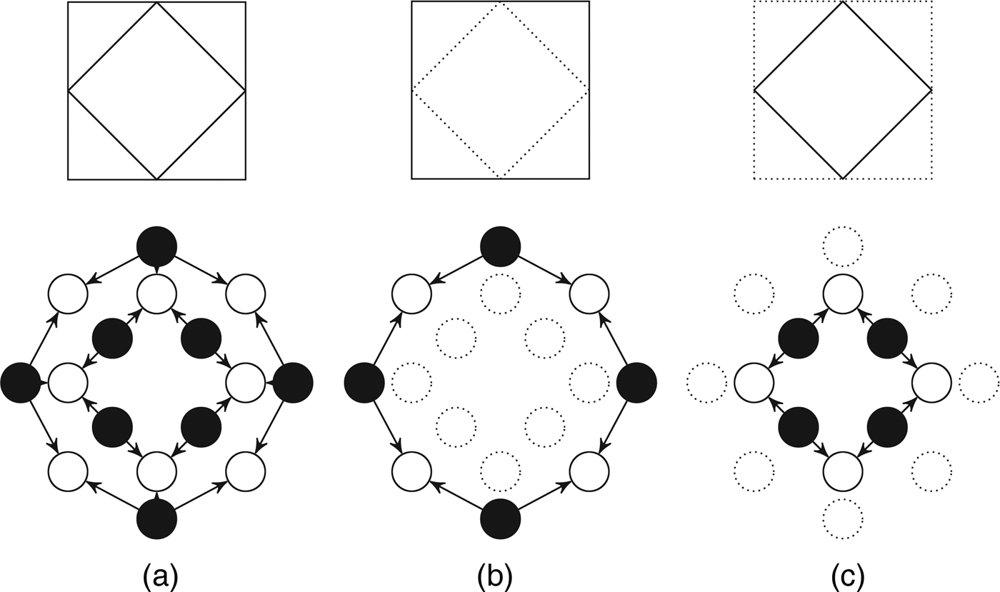
First, the geometrical topology of the shape is to be determined. The main issue here is that shapes need to be represented in such a way that the pattern shape of rules should be detected as a (sub)shape in the given shapes. In order to do this, maximal lines are created, after which the intersections and endpoints of these maximal lines are calculated in order to obtain a complete representation. Maximal lines (Stiny, Reference Stiny1980) are lines created by combining all collinear line segments that touch or overlap. The use of maximal lines results in an unambiguous interpretation of the shape, in which lines do not consist of smaller line segments. These maximal line entities are represented as edge nodes in the graph. In addition, the intersections and endpoints of the maximal lines are detected in the floor plan, and added as vertex nodes in the graph. The edge-vertex relations between the edge and vertex nodes are added to complete the geometrical topology of the graph. At this moment, the resulting graph represents the topology of the shape, but the shape is not limited to a specific geometrical realization. In this sense, the graph accounts for several parametric variations of the shape, which can be constrained by adding (geometrical) attributes to the nodes of the graph. The vertex nodes are attributed with coordinate geometry to constrain the graph to specific geometrical shapes. In particular, vertex nodes have x and y attributes, though this could be generalized for the three-dimensional case, for example, in the work of Heisserman (Reference Heisserman1994) or Grasl (Reference Grasl2013). To some extent, this approach allows the implementation of parametric shape grammars, because the graph can also be constrained to a set of geometrical variations instead of a single value. Figure 2a shows an example of a simple two-dimensional shape and the part-relation graph constructed so far. This graph representation highly facilitates the computation of possible rule matches, because the two squares in the shape can be found using an identical graph search pattern (see Fig. 2b,c). This example illustrates how shapes represented as part-relation graphs behave in a similar way as plain shapes, which is a result of the maximal line representation. By continuously translating shapes to graphs, and vice versa, the shape grammar implementation also supports the emergence of new shapes that arise or are formed from the shapes generated by rule applications (Grasl & Economou, Reference Grasl and Economou2013).
(a) Example of a shape of one square embedded in another, and its corresponding part-relation graph with vertex nodes (white), edge nodes (black), and edge-vertex relations (arrow). Because the shape is represented using maximal lines, the two squares can be found using identical graph search patterns (b and c). The node attributes are not shown in this figure.
Second, nongeometrical objects in the shape, if available, are to be determined, including walls, spaces, windows, and doors. These objects are typically represented as shapes in handmade drawings, and can easily be recognized by the human eye. This is not the case for computer implementations, and representing these entities using vertex and edge nodes in the graph would make the graph overly large and complex. In addition, because the calculation time of rule matching and application in graph rewriting systems heavily depends on the number of graph objects (Strobbe et al., Reference Strobbe, Pauwels, Verstraeten, De Meyer and Van Campenhout2015), compact graph representations are preferable. Following the ontology described in Figure 1, nongeometrical objects are represented as wall, space, window, and door nodes in the graph representation. In addition, the relations between the different nodes are identified and added to the graph representation, following the ontology.
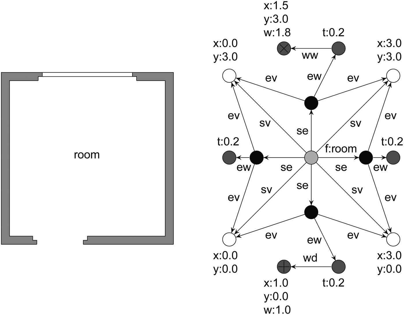
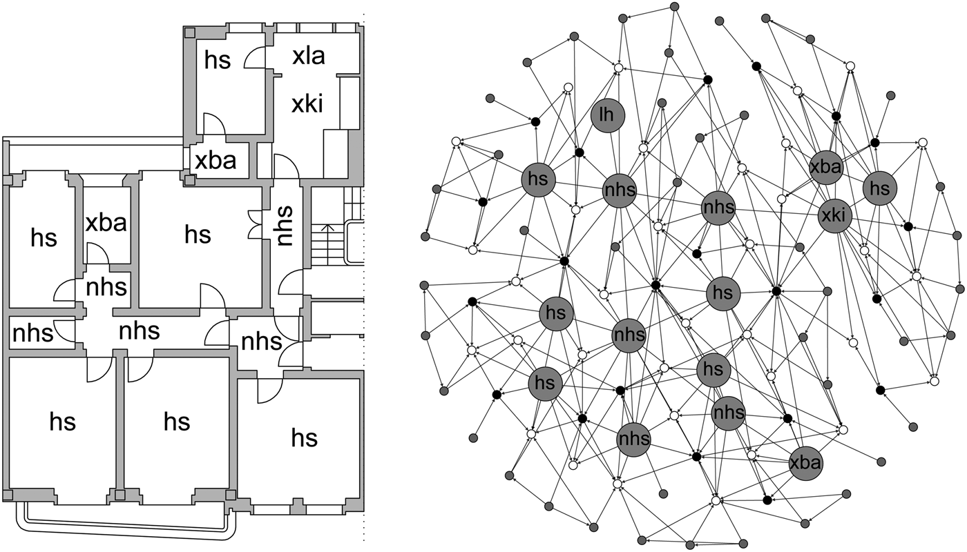
Third, attributes are associated with the nodes for different purposes: to characterize material properties of wall objects, to include additional information about the function of spaces, or to describe geometrical properties of doors and windows. An example of a drawing of a floor plan and the corresponding attributed part-relation graph is shown in Figure 3. In the visual representation (Fig. 3, left), a wall is drawn as a filled rectangular shape, which is a common way to draw walls in architectural floor plans. In the graph representation (Fig. 3, right), wall entities are defined symbolically using wall nodes and their corresponding center edges (axis lines). Attributes are used to specify the function of the space f, to characterize element properties (thickness t and width w), and to constrain the graph to a specific geometrical realization (x and y).
(Left) Example of a floor plan. (Right) Attributed part-relation graph with geometrical and nongeometrical nodes. The relations between the nodes are indicated by edges: edge-vertex (ev), space-edge (se), space-vertex (sv), edge-wall (ew), wall-door (wd), and wall-window (ww).
3.3. Step 3: Adding conditional statements
In order to implement the grammar rules, both the left-hand side and the right-hand side of the shape part of the rules need to be described using the graph representation described in the previous section. The left-hand side of a rule describes the pattern graph that needs to be matched to a given graph representation of a dwelling. The right-hand side describes the replacement graph that will replace the matched part of the given graph. A grammar rule can include deleting or manipulating existing graph nodes, creating new graph nodes, and performing computations on the graph node attributes.
For graph grammar rules, additional rule application conditions are needed, for example, to constrain the pattern graph to specific geometrical realizations, or to specify other conditional statements that are associated with shape grammar rules. In the domain of graph grammar theory, such application conditions can be defined using either attribute conditions (ACs) or negative application conditions (NACs; Ehrig et al., Reference Ehrig, Ehrig, Prange and Taentzer2006). ACs define restrictions on the attributes of graph objects. These ACs are defined as logical expressions using logical operators (including the equality operator and the relational operator). Therefore, ACs can be used to describe conditional descriptive requirements, such as geometrical requirements (e.g., area and proportion) and functional requirements. For example, considering a rule that detects a nonhabitable space in a floor plan drawing (Fig. 3); the pattern graph of this rule is associated with an AC f==nhs to constrain the matches found to spaces that have an attribute f equal to the value nonhabitable space nhs.
NACs specify requirements for nonexistence of graph objects. While an AC is defined over attribute variables, NACs define conditions about the nonexistence of graph nodes, edges, or even a specific subgraph. NACs do not have a direct equivalent in the shape grammar formalism; however, they are useful to guide and control rule application. NACs can be used to ensure that rules are applied only if specific graph objects are nonexistent. For example, considering a rule that assigns a specific function to a space in the floor plan, only if this function has not yet been assigned to another space, a NAC can be used to ensure that no other spaces with this function exist.
3.4. Methodology
In order to evaluate the feasibility of the implementation approach described in the previous section, we have implemented part of the RdB transformation grammar, originally developed by Eloy (Reference Eloy2012). The implementation is based on a JAVA development environment for graph rewriting, called AGG (http://user.cs.tu-berlin.de/~gragra/agg/). The existing editor in AGG is used to develop the grammar, and the available algorithms are used for automatic rule matching and rule application (Taentzer, Reference Taentzer2004). We have built an interface on top of the underlying graph framework that shows a visual representation of the shape grammar derivation process. In other words, the graphs are used for the computer representation and computation of shapes, rules, and grammars, while a visual representation is shown to the designer. This corresponds to Tapia's characterization of a shape grammar interpreter: “the computer handles the bookkeeping tasks … and the designer specifies, explores, develops design languages, and selects alternatives” (Tapia, Reference Tapia1999). The focus of this paper is on the implementation of the RdB transformation grammar to a graph-theoretic grammar, and not so much on the interface of the presented tool. Nevertheless, several approaches exist for providing designers with visual and interactive functionality to develop and explore grammars (McKay et al., Reference McKay, Chase, Shea and Chau2012; Strobbe et al., Reference Strobbe, Pauwels, Verstraeten, De Meyer and Van Campenhout2015). Automated shape grammar tools have several levels of automation, ranging from a stand-alone tool, in which the generation of a solution is totally controlled by the computer, to a lower level of automation, where derivation and exploration is guided by the designer (Chase, Reference Chase2010).
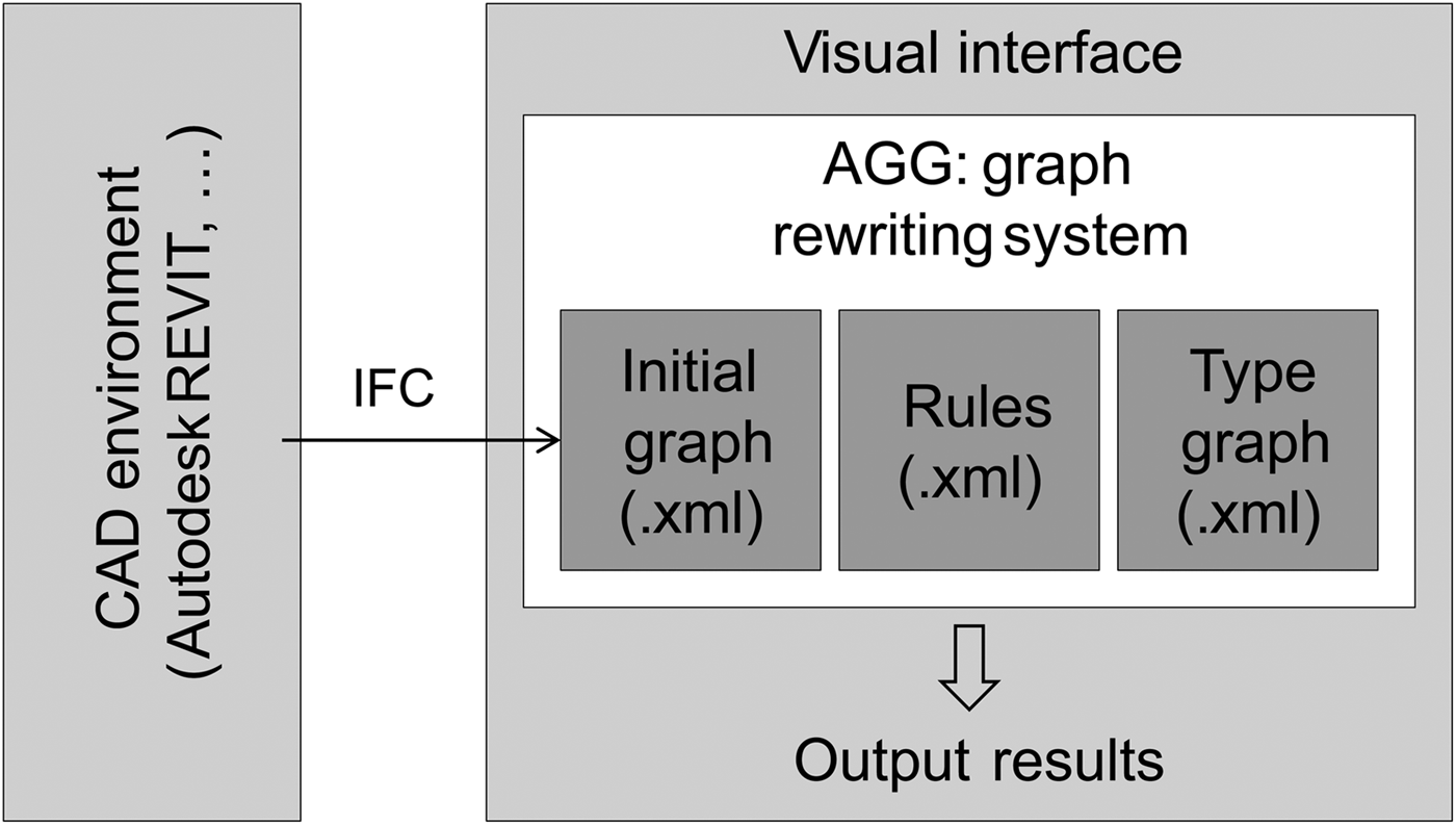
The proposed implementation approach is also embedded within a commercial CAD environment to make the shape grammar formalism more accessible to students and practitioners. In particular, shapes drawn in a common CAD format can be converted to attributed part-relation graphs. At the moment, it is possible to convert industry foundation classes (IFC) files to graphs, which are described in an Extensible Markup Language format. IFC is an object-based data model that is intended to describe building and construction industry data. Following the approach described in Section 3, geometrical (vertex and edge) and nongeometrical entities (space, wall, door, and window) found in the IFC model are first added as nodes to the graph. More specifically, these entities correspond to IfcCartesianPoint, IfcPolyline, IfcSpace, IfcWallStandardCase, IfcDoor, and IfcWindow in the IFC model, respectively. In the next step, the relations between the nodes are determined and connected by links. Subsequently, when the IFC model is imported to the shape grammar implementation tool, the properties of the IFC entities are read (e.g., wall material properties, the width and height of doors and windows, and other properties), and they are added to the corresponding graph nodes. Figure 4 shows how the grammar implementation system is integrated within a wider CAD environment. A more elaborated user interface that supports enhanced exploration abilities is described in previous work (Strobbe et al., Reference Strobbe, Pauwels, Verstraeten, De Meyer and Van Campenhout2015). The output results of the graph transformation process are shown (visually) in the interface, allowing designers to automatically generate designs in the language of the grammar.
Integration of the shape grammar implementation system within a wider computer-aided design environment. The output results of the graph transformation process are shown in the visual interface.
4. CASE-STUDY: RdB TRANSFORMATION GRAMMAR
In this section, we describe the implementation of the RdB transformation grammar, developed on paper by Eloy (Reference Eloy2012). The RdB transformation grammar provides an answer to the need for mass refurbishment of the existing housing stock in Lisbon, Portugal. In particular, a large part of the existing housing stock in Lisbon shows several constructional and functional problems, resulting in unsuitable housing in terms of contemporary comfort and accessibility standards. The RdB transformation grammar constitutes a formal methodology to generate alternative housing solutions that meet the current standards, depending on specific client needs and cost requirements. Moreover, the grammar includes various customized transformation strategies to adapt existing RdB houses to the current standards, depending on specific client needs. These transformation strategies describe how an existing dwelling is transformed to meet the standards and requirements in the form of transformation rules. In recent work, Eloy and Duarte (Reference Eloy and Duarte2014) describe the process undertaken to develop the RdB transformation grammar, and discuss how both the knowledge of the designer and knowledge acquired from other experiences of refurbishment are incorporated in the grammar. The implementation of this grammar to a computerized grammar can be seen as the next step in the development of a (semi)automated methodology to support mass housing refurbishment.
4.1. The original RdB transformation grammar
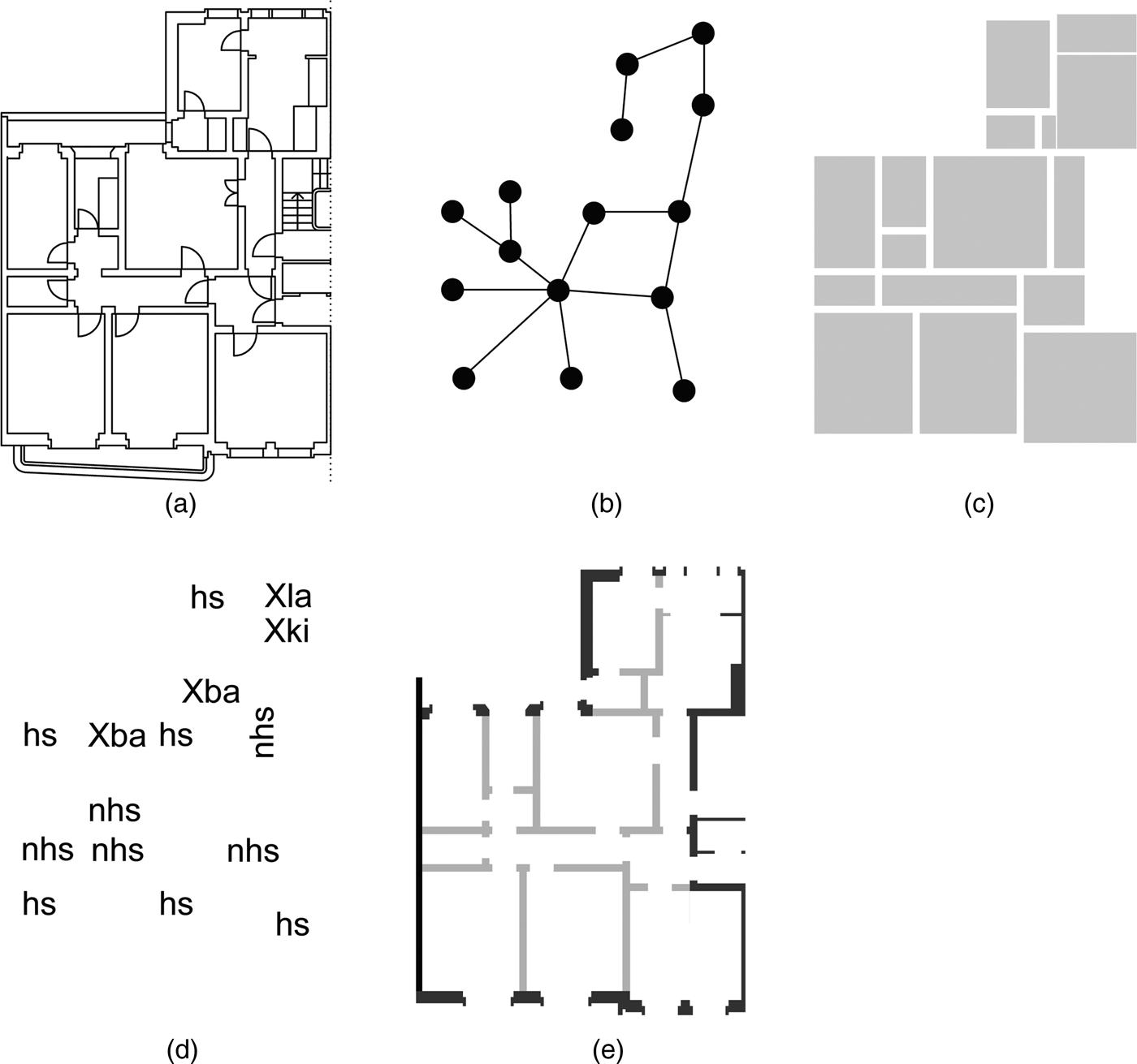
The original RdB transformation grammar uses a compound representation of the designs and the rules. For example, Figure 5 shows the compound representation of an existing RdB dwelling using five different representations, corresponding to five algebras: U12, U02.U12, U22, V02, and W02. In particular, the algebra U12 combines lines in a two-dimensional plane to represent floor plans of dwellings (Fig. 5a), the algebras U02 and U12 are used to represent topological relations between spaces of dwellings (Fig. 5b), and the algebra U22 is used to represent spatial voids in floor plans of dwellings (Fig. 5c). Further, an algebra V02 consists of labels and is used to control rule application or to associate nongeometrical information with shapes. In this case, labels are attributed to each space in a RdB dwelling (Fig. 5d), for example, habitable space (hs), nonhabitable space (nhs), existing kitchen (Xki), and existing bathroom (Xba). An algebra W02 consists of weights and is used to incorporate shape properties, for example, to characterize construction systems for walls (Fig. 5e), including brick walls (dark gray), structural elements, side walls (black), and partition walls (light gray). As a result, a dwelling is described using five different representations in the RdB transformation grammar.
Compound representation of an existing Rabo-de-Bacalhau dwelling: (a) floor plan representation of the dwelling, (b) topological configuration of spaces in the dwelling (continuous lines for door connections and hidden lines for adjacency between rooms), (c) representation of spatial voids in the floor plan, (d) labels, and (e) weights. This image is reproduced from A Transformation Grammar-Based Methodology for Housing Rehabilitation: Meeting Contemporary Functional and ICT Requirements, by S. Eloy, Reference Eloy2012, PhD Thesis, TU Lisbon. Copyright 2012 by S. Eloy. Reprinted with permission.
The rules of the RDB transformation grammar define the different transformation strategies that can be applied in order to meet the current standards and requirements. These rules are also defined using a compound representation. First, the rules consist of a shape part using two or more of the representations discussed in the beginning of this section. At least two representations are needed; for example, the graph representation and the labels are sufficient for rules that consider topological aspects only. However, in other cases, a combination of multiple or even all representations is needed to incorporate the desired design knowledge in the rules. Second, the rules consist of a conditional part to express additional rule application conditions considering dimensional or functional aspects of the shape. These application conditions provide a mechanism to control rule application toward specific limited cases. Third, a descriptive part is added to keep track of spaces required by the transformation strategy, spaces already assigned to the given dwelling, and spaces still available for assignment. In the original RdB transformation grammar, three sets are used to control the assignment of spaces: a set of existing spaces (E), a set of required spaces not yet assigned (Z), and a set of spaces already assigned to the proposed dwelling (Z’). In general, the descriptive part is defined as a transformation on a tuple of elements. Several example rules are shown later in this paper, indicating the different rule parts. An extensive overview of the RdB transformation grammar rules is given in the work of Eloy (Reference Eloy2012).
The RdB transformation grammar provides an interesting case study for implementation, because the grammar is extensive (142 shapes rules) to explore manually, and the implementation serves as the next step in the development of a (semi)automated approach for supporting mass housing refurbishment. In addition, it provides an interesting case study to investigate the proposed implementation approach, because the grammar uses multiple representations (in different algebras), subshape detection, labels, and parametric rules. Another difficulty in implementing this grammar is how to implement the large number of conditional statements that are associated with the rules.
4.2. Translation of the original grammar to a computerized grammar
Following the approach described in Sections 3.1–3.3, the first step is the definition of the ontology. The RdB transformation grammar involves the transformation of existing dwellings to dwellings that meet the current standards and client needs. These dwellings are represented in multiple ways: a two-dimensional floor plan, a topology graph, a spatial void representation, and the representation of labels and weights. The goal is to find a type graph (ontology) for an attributed part-relation graph that can account for all these representations in one. The type graph shown in Figure 1 proves to be sufficient for this purpose. The geometrical node types vertex and edge are used to represent the geometry of the floor plan, the node type space and the relation access-to are used to represent the topology graph and spatial voids, and the node types wall, door, and window are used to represent nongeometrical entities in the floor plan.
In order to construct the attributed topology graph, attributes are associated with the nodes to characterize construction systems for walls (brick walls, structural elements, side walls, and partition walls), to include information about the functionality of spaces, and to describe geometrical properties of doors and windows. In particular, information about the construction system is added as an attribute s to the wall nodes in the graph. In addition, labels cx, cy, wi, and he describe the position, width, and height, respectively, of doors and windows. In some cases, labels are used to add information not provided by shapes (such as the function of spaces and information about technical appliances; e.g., smoke detector and temperature detector). The label f describes the function of a space (e.g., habitable space hs and nonhabitable space nhs). In other cases, labels are used to control rule application or, in other words, to specify which rules can be applied at a specific moment in the transformation process. As a result, the floor plan is represented as an attributed part-relation graph that is at the same time compact and maintains sufficient semantic meaning.
Figure 6 shows the visual and graph representation of an existing RdB dwelling, described in the work of Eloy (Reference Eloy2012). For illustrative purposes, the edge types are not shown, and only one node attribute is shown (function f). The resulting graph contains 113 nodes, 294 edges, and 126 attributes. The graph representation is used for the computation of shapes, rules, and grammars, while the visual representation is shown to the designer. This dwelling is one possible starting point for the transformation process using the RdB transformation grammar.
(Left) Original floor plan from a Rabo-de-Bacalhau dwelling described in the work of Eloy (Reference Eloy2012). (Right) Attributed part-relation graph of the floor plan. For illustrative purposes, the edge types are not shown, and only one node attribute is shown (function f).
For the RdB transformation grammar, there is no predefined initial shape. Instead, there are countless possibilities, because the initial shape can be the floor plan of any existing RdB dwelling. The development of these initial floor plan shapes (using a graph-based representation) is not part of the RdB transformation grammar, but they are usually drawn in traditional CAD environments. Figure 7 demonstrates the conversion from an initial RdB dwelling (modeled in Autodesk REVIT 2014) to the graph rewriting environment, using the IFC file format. Some details of the floor plan (e.g., balcony and constructional elements) are deliberately left out because they are less relevant in the scope of this experiment.
(Left) Model of a Rabo-de-Bacalhau dwelling in Autodesk REVIT 2014 and (right) visual representation of the dwelling in the graph rewriting environment.
4.3. Three example rule types
In order to demonstrate the feasibility of the proposed approach, we discuss three relevant types of rules from the RdB transformation grammar: (1) assignment rules, (2) rules to connect spaces by eliminating walls, and (3) rules to divide spaces by adding walls (Eloy, Reference Eloy2012). For each rule type, an example rule from the original grammar is shown, together with the corresponding implemented rule.
4.3.1. Assignment rules
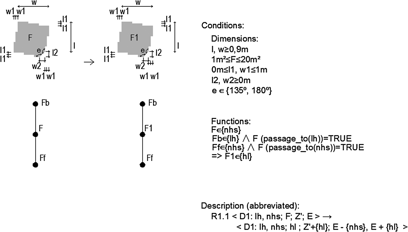
Assignment rules allow the required functions to be assigned to the existing spaces. An example assignment rule is shown in Figure 8. This rule transforms a nonhabitable space (label nhs) to a new hall space (label hl) by modifying the label from the matched space, both in the floor plan representation and the topology representation. As mentioned in Section 4.1, each rule contains three parts: a shape part, a conditional part, and a descriptive part. The shape part of the rule consists of a parametric shape to create correspondence between the geometries of the different spaces within the dwellings studied (parameters w, l, w1, w2, l1, and l2). The conditional part of the rule defines dimensional conditions (size and area), on the one hand, and functional conditions, on the other. In particular, a space can only be assigned as a hall space, if this space is connected to a lift hall (label lh) and another nonhabitable space. The descriptive part of the rule is described as an operation on a four-tuple with the following format: <Dn: Fb, Ff ; F; Z′; E> → <Dn: Fb, Ff; F1; Z′ + {F1}; E – {F}, E + {F1}>, where Dn denotes the stage in the derivation, Fb and Ff denote the back and front space, F denotes the function of the space involved, Z′ denotes the set of spaces assigned to the proposed dwelling, and E denotes the set of existing spaces. The rule in Figure 8 removes only the nonhabitable space that is under consideration in the rule (using a unique identifier) from the set of current spaces E, and adds the hall space to both the list of current spaces E and the list of already assigned spaces Z′. Please refer to Eloy (Reference Eloy2012) for an elaborated discussion on the assignment rules of the RdB transformation grammar.
Example rule from the Rabo-de-Bacalhau transformation grammar: assignment of hall. This image is adapted from A Transformation Grammar-Based Methodology for Housing Rehabilitation: Meeting Contemporary Functional and ICT Requirements, by S. Eloy, Reference Eloy2012, PhD Thesis, TU Lisbon. Copyright 2012 by S. Eloy. Adapted with permission.
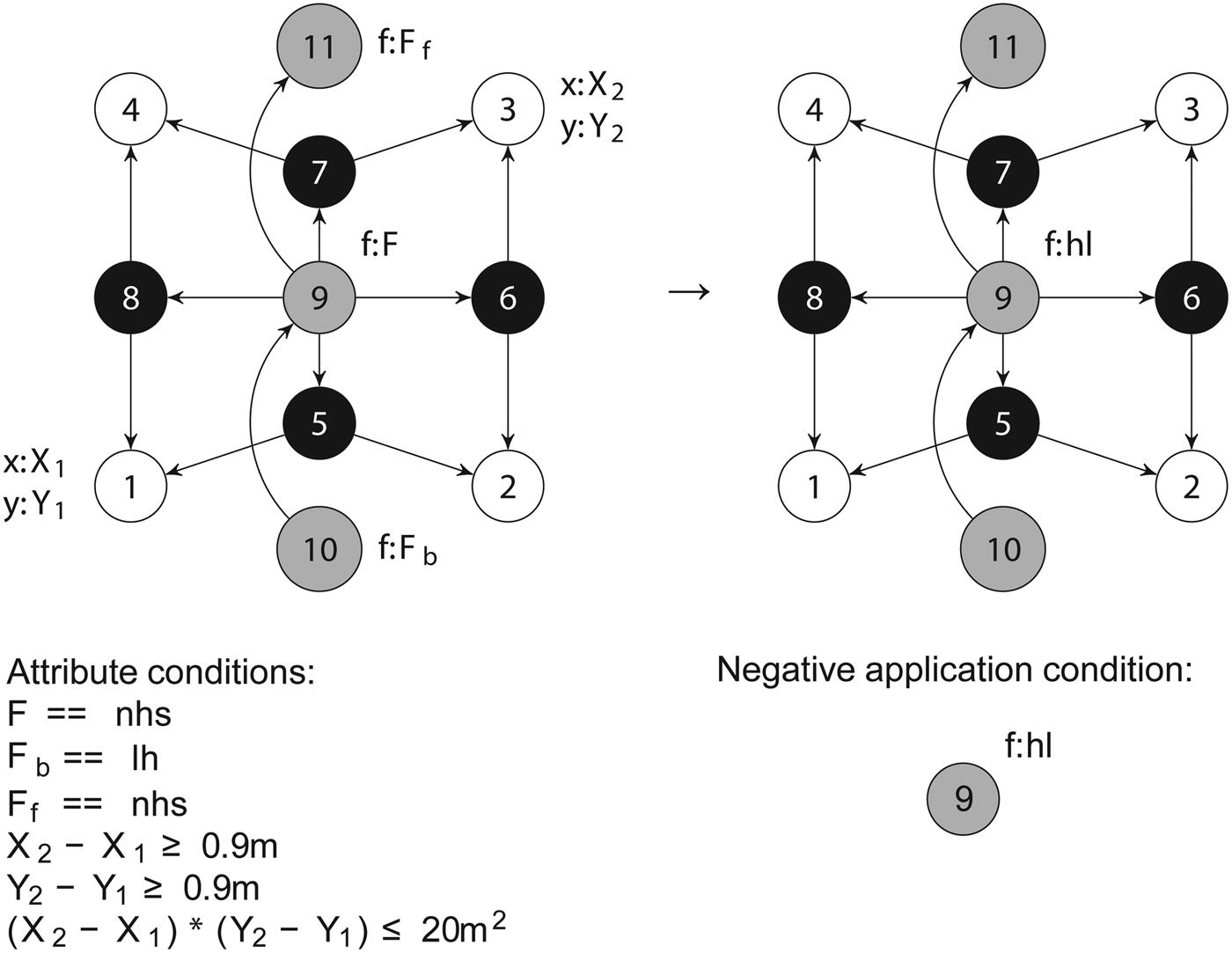
The graph representation of this rule is given in Figure 9. The pattern graph of the rule consists of three space nodes with the functions Fb, F, and Ff, together with the geometrical vertex and edge nodes of the middle space. In the original rule, the spatial void is drawn as a parametric shape in order to apply to all different geometries that can be found. In the implemented graph rule, the topology of all quadrilateral shapes (square, rectangle, and parallelogram) with different dimensions is represented. As a result, the implemented graph rule is a parametric rule in the sense that all geometrical realizations of a quadrilateral shape can be matched. Because most spaces in the RdB dwellings are quadrilateral, such representation is sufficient in most cases. Nevertheless, the original rule also includes irregular spaces (w1, w2, l1, and l2), and therefore, a pattern graph should be implemented for each topology that can be found (pentagon, hexagon, and other polygons). In other words, the pattern shape of the original rule has multiple pattern graph equivalents. Several ACs are used to specify the conditional requirements of the original rule: the length (Y4 – Y1) > 0.9 m, the width (X4 – X1) > 0.9 m, the area (Y4 – Y1) × (X4 – X1) < 20 m2, and some functional conditions concerning the spaces F, Fb, and Ff. In addition, a NAC is added to the replacement graph to ensure that a hall space has not already been assigned to the dwelling. In other words, NACs provide the functionality to keep track of the spaces already assigned, and spaces still available for assignment. The rule morphism specifies which graph objects of the pattern graph are preserved in the replacement graph, which is indicated in Figure 9 by showing identical numbers for each graph object in both rule sides. In this case, the replacement graph of the rule is nearly identical to the pattern graph (the rule does not change the topology), but the f attribute is changed to hl in order to assign the hall space in the dwelling.
Graph representation of the hall assignment rule, consisting of (left) a pattern graph, (right) a replacement graph, and (bottom) attribute conditions and negative application conditions. The numbers indicate the rule morphism between the pattern graph and the replacement graph.
The implementation of the rule on a computer system demonstrates that the original rule is underconstrained. In particular, the pattern graph of the original and implemented rule can be matched to two different sets in the dwelling, returning two identical results. The space nodes with labels Fb and F are matched to the lift hall and the entrance adjacent to the lift hall, respectively, but the third space node with label Ff can be matched to two different nonhabitable spaces in the dwelling (Fig. 10). Therefore, the rule results in two distinct, but identical, rule application results. This behavior of the rule is difficult to foresee, because such forms of ambiguity in the rules often remain unnoticed. However, this is not the case for computer implementations of grammars, in which such form of ambiguity becomes directly noticeable. This is an example of how designers can learn from the computer implementation about the grammar itself.
Two possible rule applications of the assignment rule. The space nodes with labels Fb and F are matched to the lift hall and the entrance adjacent to the lift hall, respectively. The space node with label Ff can be matched to two different nonhabitable spaces in the Rabo-de-Bacalhau dwelling.
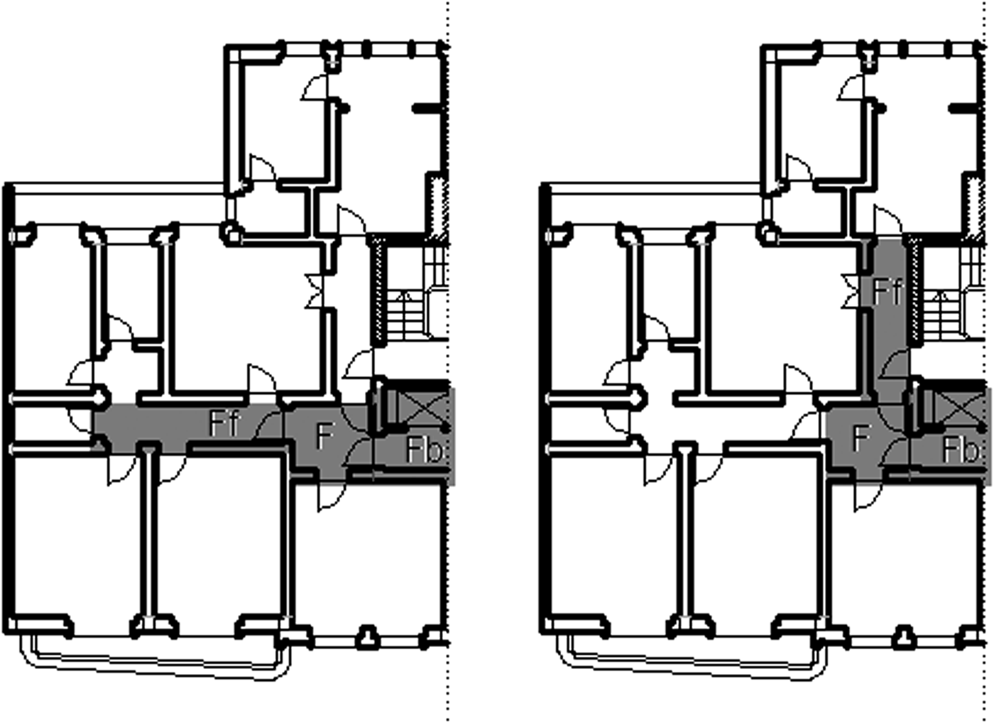
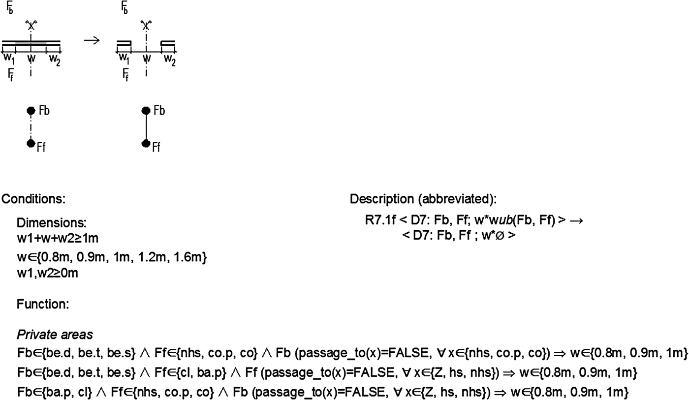
4.3.2. Connection rules
Connection rules connect spaces by eliminating parts of a straight wall, thereby connecting (or enlarging) spaces. An example rule to connect two adjacent spaces, if several conditions are satisfied, is shown in Figure 11. In this case, the representation of the rule is simplified for illustrative purposes: only the conditional requirements for private spaces are shown (bottom Fig. 11), while requirements for other spaces are omitted. The conditional part of the rule describes that only specific adjacent spaces can be connected, for example, single, double, or triple bedrooms (label values be.s, be.d, and be.t, respectively) with nonhabitable spaces and corridors (label values nhs and co, respectively). The descriptive part of the rule is described as an operation on a tuple, having the following format: <Dn: F1, F2; w × wcs(F1, F2)> → <Dn: F1, F2; w′ × wcs(F1, F2)>, where w denotes the width of the wall, and wcs denotes the wall construction system. In particular, a part (w) of the existing brick wall (wub) is demolished to allow for a door opening in the wall between two spaces (w*Ø). Please refer to Eloy (Reference Eloy2012) for an elaborated discussion on the connection rules of the RdB transformation grammar.
Example rule from the Rabo-de-Bacalhau transformation grammar: connecting two adjacent spaces by eliminating part of a straight wall. Only the conditions for private spaces are shown here. This image is adapted from A Transformation Grammar-Based Methodology for Housing Rehabilitation: Meeting Contemporary Functional and ICT Requirements, by S. Eloy, Reference Eloy2012, PhD Thesis, TU Lisbon. Copyright 2012 by S. Eloy. Adapted with permission.
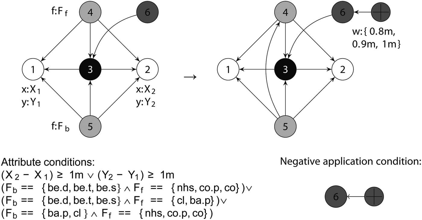
The graph representation of this rule is given in Figure 12. The pattern graph consists of two space nodes, together with nodes representing their shared edge, wall, and vertex entities. The geometrical and functional requirements from the original rule are implemented as ACs. These attribute conditions are described in a similar format as the original rule, using logical conjunctions and disjunctions to express the different cases when the rule can be applied. Again, only the ACs for the connection of private spaces are shown in Figure 12, for illustrative purposes only. In addition, a NAC is added to the replacement graph to ensure that the two spaces are not yet connected. The replacement graph adds an additional door node to the matched graph (width 0.8, 0.9, 1, 1.2, or 1.6 m) and an access-to relationship between the two space nodes.
Graph representation of the adjacent space connecting rule, consisting of (left) a pattern graph, (right) a replacement graph, and (bottom) attribute conditions and negative application conditions.
Depending on the given conditional requirements, this rule can be applied to a given dwelling in many ways. Using the original grammar rule, developed on paper, it is difficult to detect all the possibilities where the rule can or cannot be applied, because of the large number of conditions that need to be considered. According to previous research by Woodbury and Burrow (Reference Woodbury and Burrow2006), herein lies one of the main benefits of CAD tools: their ability to support designers in exploring large design spaces. A computer system can enumerate all possible rule applications automatically. In this way, designers benefit from computer implementations, because they can focus on selecting and exploring alternatives, leaving the underlying rule application and calculation tasks for the computer.
4.3.3. Division rules
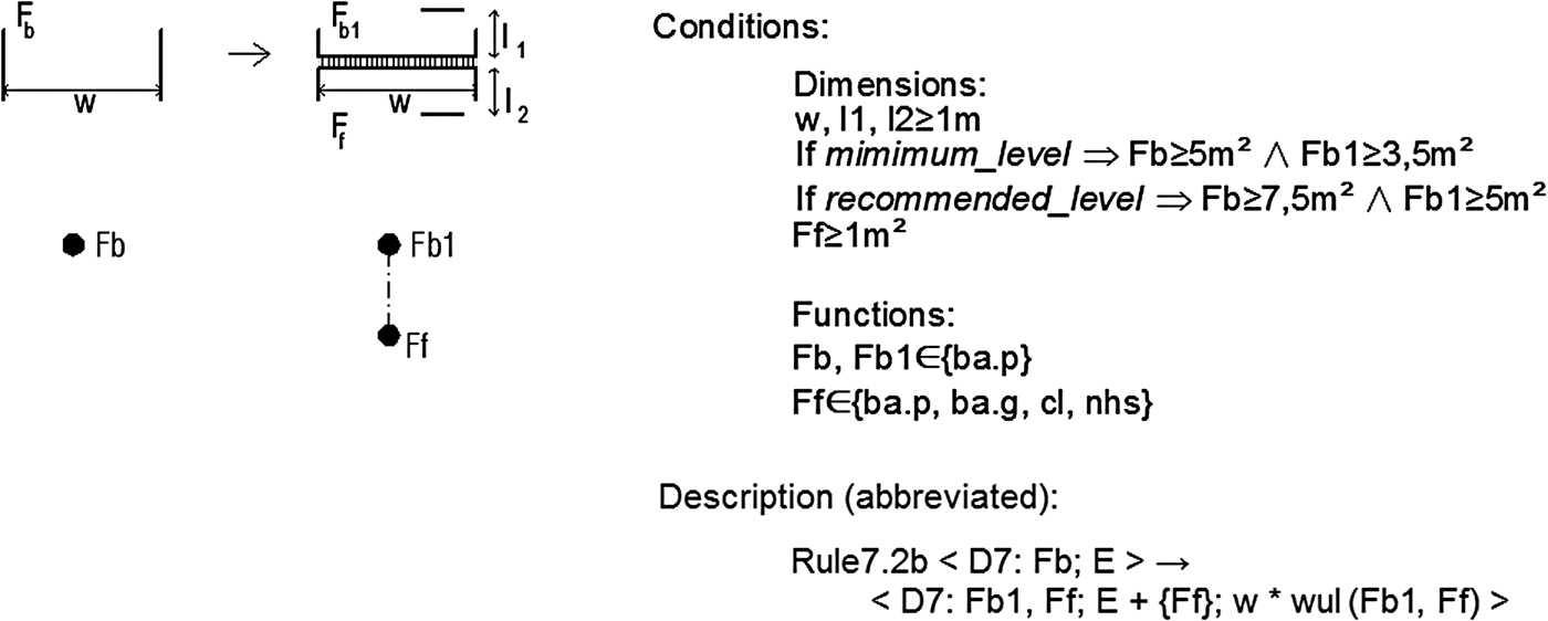
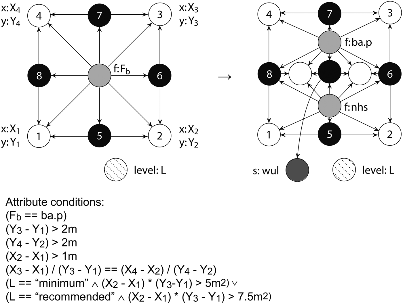
Division rules divide a space by adding a wall between two parts of the space. An example rule to divide a bathroom by adding a wall, if several conditions are satisfied, is shown in Figure 13. The shape part of the rule describes how a new wall is added perpendicular to an existing wall of a space that has been assigned as a private bathroom (label Fb has the value ba.p). Several conditional requirements are defined, for example, to ensure that the area of the spaces meet a predefined comfort level: a bathroom larger than 3.5 m2 for a minimum level of comfort, and a bathroom larger than 5 m2 for a recommended level of comfort. The descriptive part of the rule is described as an operation on a tuple with the following format: <Dn: F1; E> → <Dn: F1, F2; E + {F2}, w × wcs(F1, F2)>. In particular, a light partition wall (wul) is added with a specific width (w) to divide the space. Please refer to Eloy (Reference Eloy2012) for an elaborated discussion on the division rules of the RdB transformation grammar.
Example rule from the Rabo-de-Bacalhau transformation grammar: dividing a private bathroom space by adding a wall. This image is adapted from A Transformation Grammar-Based Methodology for Housing Rehabilitation: Meeting Contemporary Functional and ICT Requirements, by S. Eloy, Reference Eloy2012, PhD Thesis, TU Lisbon. Copyright 2012 by S. Eloy. Adapted with permission.
The graph representation of this rule is given in Figure 14. The pattern graph of the rule consists of one space node with a label Fb, and eight other nodes that represent four boundary edges and four vertices of the space. The information of the edges and vertices is needed to calculate the area and length of the space that are dependent on the shape. Similarly to the assignment rule in Figure 9, this rule is parametric in the sense that all geometrical realizations of a quadrilateral shape can be matched. For irregular shapes, different pattern graphs should be implemented, and therefore, the original rule has multiple graph rule equivalents. In order to create a perpendicular wall, the two opposing edges need to be parallel, which is achieved by using an AC to ensure that the slope of the two edges is identical: (X3 – X1)/(Y3 – Y1) == (X4 – X2)/(Y4 – Y2). The other geometrical requirements (w, l1, l2) are specified to ensure that spaces have sufficiently large edge dimensions: (Y3 – Y1) > 2 m, (Y4 – Y2) > 2 m, (X2 – X1) > 1 m. In order to implement the conditional requirement of the predefined comfort levels (minimum or recommended), it is necessary to extend the type graph in Figure 1 with an additional node type comfort level that has an attribute level. Depending on the value of this level attribute L, a specific AC is applicable: [L == “minimum” ∧ (X2 – X1) × (Y3 – Y1) > 5 m2] [L == “recommended” ∧ (X2 – X1) × (Y3 – Y1) > 7.5 m2]. The replacement graph adds a light partition wall (label s has value wul) that divides the space in two new spaces (private bathroom and nonhabitable space). Two new vertex nodes are created that are incident to the two existing parallel edges. Next, a new edge node is created between the two vertices, together with a new wall node. The values of the attributes of the new vertex nodes depend on the area of the two new spaces and the specified comfort level (minimum or recommended).
Graph representation of the division rule, consisting of (left) a pattern graph, (right) a replacement graph, and (bottom) attribute conditions.
Finally, the RdB transformation grammar includes several other types of rules, which are not discussed in this paper. For example, one rule type in the grammar is used to permute functions between spaces. This rule type is very similar to the assignment rule type, and can thus be implemented using the same approach. Another example is a rule for changing the derivation stage in the transformation process. In this case, labels are used to include information about the derivation stage and to control the derivation process. Lastly, the RdB transformation grammar consists of rules for integrating information, communications, and automation technologies (ICAT) in the dwellings. These rules use labels to incorporate information about the ICAT in the dwellings. Therefore, they can be implemented as graph rules that modify the attributes of the nodes that correspond with the locations of the ICAT.
4.4. Results of the implementation
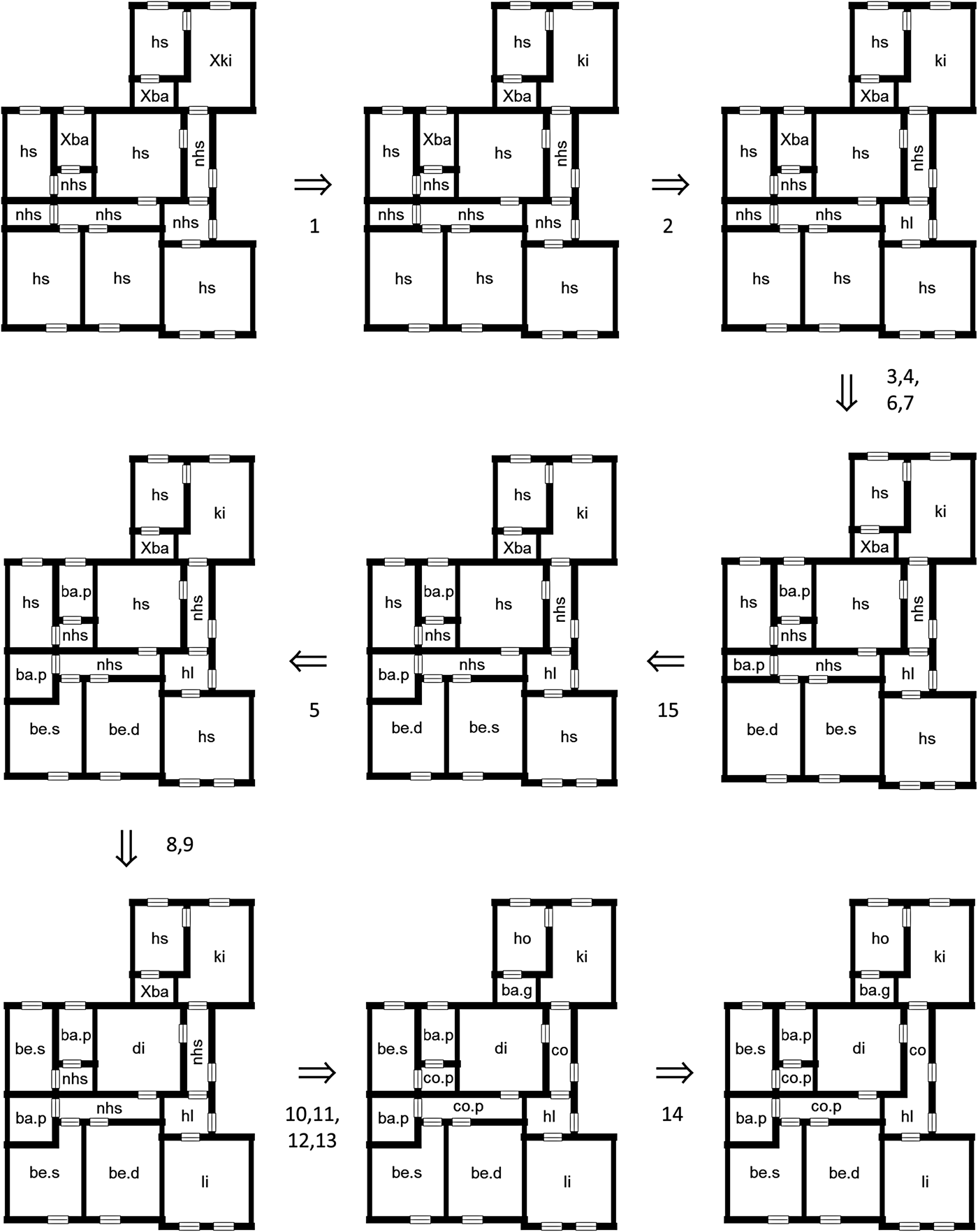
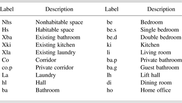
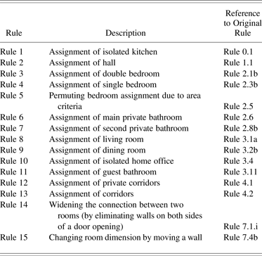
A part of the RdB transformation rules has been implemented using the proposed methodology described in Section 3.4. In particular, we have implemented rules of the rule types described in Section 4.3: assignment rules, rules to connect spaces by eliminating walls, and rules to divide spaces by adding walls. An example of a derivation for a possible RdB dwelling is shown in Figure 15. The shape rules used at each step of the derivation are shown between the intermediate derivations. For illustrative purposes, several derivation steps are merged (as indicated in Fig. 15), because the changes to the floor plan are subtle. The labels that have been used for the derivation process are described in Table 1. The rules that have been used are shown in Table 2. For each rule, a short description is given, together with a reference to the original rule in the RdB transformation grammar (Eloy, Reference Eloy2012).
Example of a derivation of a possible Rabo-de-Bacalhau dwelling. The shape rule used at each step of the derivation is shown between the intermediary steps. For illustrative purposes, several derivation steps are merged.
The labels used for the representation of housing designs
The transformation rules used during the derivation process
Note: A short description is given for each rule, together with a reference to the original rule in Eloy (Reference Eloy2012).
5. DISCUSSION
In this section, we describe several findings and issues encountered during the implementation and evaluation of the proposed approach and the RdB transformation grammar case study. First, while human designers are able to reinterpret shapes and shape rules during a shape grammar derivation process, computer systems are able to “interpret” the visual information in terms of the ontology used, or in this case, using the underlying graph representation. Therefore, emergence of shape features or properties that are not apparent in the initial definition of the shapes is not readily supported, but we describe how computer-implemented grammars can support emergence for shapes in the algebra in U12 in Section 3.1. The main benefits of the approach set out in this paper are gained for extensive and complex grammars that are difficult to explore manually, because computer systems enable easier rule application. The proposed approach in this paper has been evaluated for the RdB transformation grammar, which is a complex shape grammar with multiple representations (in different algebras), subshape detection, labels, and parametric rules. The computer implementation of this grammar is a good way to quickly generate several outcomes (in the context of the mass housing program).
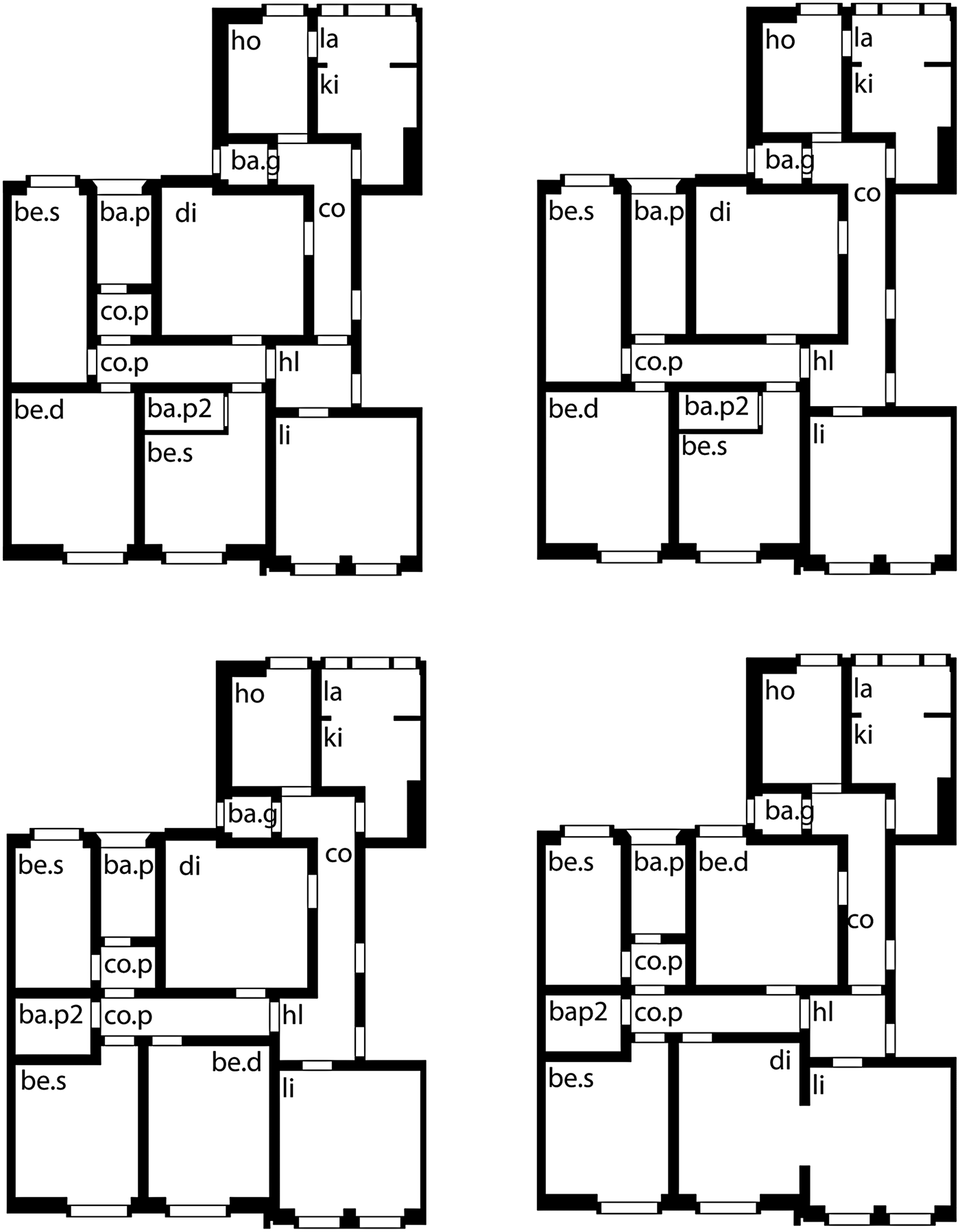
Second, while several objects, such as spaces, walls, doors, and windows, can be considered as geometrical entities from an architectural point of view, they are treated as nongeometrically in the implemented grammar. The representation of such objects using only geometrical graph nodes (such as vertex and edge) would result in complex graph representations. Among the main benefits of this approach is that the initial shape and the pattern and replacement shape of the rules can be represented quite intuitively, and with as little graph objects as possible. Because rule matching is the most runtime intensive step in the graph rewriting process, it is important to keep the number of graph objects low. Moreover, the calculation time of rule matching depends on the size of the initial graph and the pattern graph. In this paper, we have used an ontology that mixes geometrical with nongeometrical node types. In order to validate this approach, we have generated four more derivation examples (Fig. 16), starting from the same initial design of Figure 15 and the same inhabitants requirements (comfort level, etc.). These results show some variation in the placement of the dining room (either north or south, connected to the living room), the placement of the private bathroom, and the placement of the corridors. The entire derivation shown in Figure 15 and the four resulting designs in Figure 16 can be generated in approximately 1–2 s using a common personal computer (we used an Intel Core 2 Quad 3.00-GHz processor with 4 GB RAM and 64-bit Windows 7). This experiment demonstrates how the computer-implemented grammar might support a designer in exploring design alternatives. Even more alternatives could be generated by taking into account the parametric variables in the rules, and by using different inhabitants requirements. While an extensive benchmarking of computer-implemented shape grammars would be very interesting, it is out of scope in this paper, and therefore it is part of our current ongoing and future research. More details on performance measurements of grammar implementations can also be found in earlier research work (Grasl & Economou, Reference Grasl and Economou2013; Strobbe et al., Reference Strobbe, Pauwels, Verstraeten, De Meyer and Van Campenhout2015).
Four alternative automated productions of other Rabo-de-Bacalhau dwellings, based on the same initial design of Figure 15 and the same inhabitants requirements. The resulting designs show some variation in the placement of the dining room, the private bathroom, and the corridors.
Third, the implementation of the RdB transformation grammar has shown some unexpected rule application results, largely due to the original rules being underconstrained or ambiguous. Human designers can easily make meaning from visual patterns in the rules, and as a result, such forms of ambiguity in the rules often remain unnoticed. This is not the case for computer implementations of grammars, in which such form of ambiguity becomes directly noticeable. As a result, the attempt to implement a grammar on a computer system leads to a deeper understanding of that grammar, and might result in the further development of the grammar. In this way, designers might learn from the computer implementation of their shape grammar about the grammar itself.
Fourth, as a result of the structured (graph-based) representation of computerized grammars, rewriting systems might be used to enumerate all possible rule applications automatically. Using the original grammar, developed on paper, it is often difficult to detect all the possibilities where rules can be applied, because of the large number of conditions that need to be taken into account. Therefore, a computer system might be used to handle automatic rule application and to handle the management of possible design alternatives. In this case, the designer can focus on selecting and exploring these alternatives. This results in a mixed human–computer interaction, in which the computer supports the designer in exploring the language of a grammar, or a design space in the more general sense. This is achieved by using a visual interface (that has been built on top of the underlying graph rewriting framework), which shows all the possible design alternatives that can be selected at a certain point in the derivation process. Figure 17 shows a screenshot taken during the derivation process of one RdB dwelling, in which the rules are shown in a textual manner (top left), the current design state is shown in a visual manner (bottom left), and the possible design alternatives are enumerated in a list (right). As a result, the designer can navigate in the design space of the implemented grammar, which is an important amplification strategy for computers to support human design space exploration. In previous research work (Strobbe et al., Reference Strobbe, Pauwels, Verstraeten, De Meyer and Van Campenhout2015), a more general framework for design space exploration using shape grammars is presented, together with more details about the user interface and the mixed-initiative interaction envisioned. For the RdB transformation grammar, such a human–machine interaction is beneficial, because of the large number of conditional statements in the rules, which makes it difficult to detect manually where the rules can be applied.
Screenshot taken during the derivation process of one Rabo-de-Bacalhau dwelling (top left) : the rules are shown in a textual manner, (bottom left) the current design state is shown in a visual manner, and (right) the possible design alternatives are enumerated in a list. The changes in the floor plan resulting from the rule applications are indicated in red.
Fifth, the proposed implementation approach is evaluated through a case study of the RdB transformation grammar, but the proposed approach and findings should be generalizable to other specific shape grammars. For example, the graph-theoretic representation of the Palladian grammar, described in the work of Grasl (Reference Grasl2012), can be defined using an ontology that contains node types for spaces, rooms, porticos, center rooms, exterior, and orientation (structured in a hierarchical manner), and edge types for describing east–west and north–south relations. In general, the translation of an existing shape grammar to an equivalent graph-theoretic grammar is an interesting exercise, because designers need to think about several aspects of their grammar in a different way: for example, the use of multiple graph equivalents of a parametric shape, the definition of the ontology, or the definition of conditional requirements to control rule application. As a result, the graph-theoretic equivalent of a shape grammar might operate using different underlying principles, leading to an alternative understanding of the grammar at hand, which is complementary to designing shape grammars.
6. CONCLUSION
The work presented in this paper demonstrates an approach for a graph-theoretic implementation of a shape grammar, originally developed on paper, on a computer system. The issue of the computer implementation of shape grammars is shown to be important, because the computer implementation of shape grammars concerned with modeling an existing corpus work not only enables (semi)automatic rule application but also influences the design of the shape grammar itself. A practical step-by-step approach is given for the translation of a shape grammar to an equivalent graph-theoretic grammar. The RdB transformation grammar, originally developed by Eloy (Reference Eloy2012), is used to demonstrate the details of this approach and to evaluate the feasibility. In particular, three relevant types of rules used in the RdB transformation grammar are discussed: assignment rules, rules to connect spaces by eliminating walls, and rules to divide spaces by adding walls. In order to evaluate the feasibility of the implementation approach, a part of the RdB transformation grammar is implemented, using a JAVA development environment for graph rewriting. This implementation is shown to be both feasible and valuable in several aspects. First, the proposed approach contributes to the existing state of the art on the graph-theoretic representation of shape grammars. It is shown how the implementation of a shape grammar to a computerized grammar might influence the design of the original shape grammar. Second, the work presented in this paper can be considered as an example of how shape grammars are implemented to a computer system, which might in the turn increase the impact of grammars on design practice. In particular, the development of a (semi)automated methodology to support mass housing refurbishment is described. Third, the proposed approach is embedded within a commercial CAD environment to make the shape grammar formalism more accessible to students and practitioners. Some future lines of research include the further integration of the proposed approach within a CAD environment in order to allow the results to be returned to the CAD environment, and an extensive benchmarking of the proposed implementation approach and other shape grammar implementations in general.
ACKNOWLEDGMENTS
The graph grammars are implemented using AGG, a JAVA development environment for attributed graph transformation. The research is funded by the Agency for Innovation by Science and Technology in Flanders (IWT).
Tiemen Strobbe is a PhD Researcher in the Ugent SmartLab research group in the Department of Architecture and Urban Planning and the Department of Electronics and Information Systems of Ghent University. He graduated as an engineer–architect from Ghent University, Belgium, with a Master's dissertation on the applicability of parametric design strategies. His interests and current PhD research focus on design space exploration, generative design, shape grammars, and the application of information technology in architectural design in general.
Sara Eloy is an Assistant Professor at the Department of Architecture and Urbanism (DAU) ISCTE-IUL in Lisbon, where she teaches Architectural Computer Aided Design, Computation, and Building Technologies. Eloy's research focuses on the use of shape grammar systems in architecture design, space syntax analysis, and the use of virtual and augmented reality in architecture design process and evaluation of user's space perception.
Pieter Pauwels is a Postdoctoral Researcher in the Department of Architecture and Urban Planning at Ghent University. He holds Master's and PhD degrees (2012) in engineering–architecture, both obtained at Ghent University. During his PhD research, he investigated how information system support can be provided for architectural design thinking. Pieter was previously a Postdoctoral Researcher at the Institute for Logic, Language and Computation in the University of Amsterdam. Dr. Pauwels is now working full-time on topics affiliated with building information modeling, linked building data, and linked data in architecture and construction.
Ruben Verstraeten is an Assistant Professor in the Department of Architecture and Urban Planning at Ghent University. He graduated as an engineer–architect from Ghent University. His PhD dissertation was focused on the automated compliance checking mechanisms of architectural designs. Dr. Verstraeten teaches several courses in computational design, including three-dimensional modeling, parametric design, and digital fabrication.
Ronald De Meyer is a Senior Lecturer in the Department of Architecture and Urban Planning of Ghent University and a Lecturer in the Department of Architecture and Design of Hasselt University. He graduated from the Hoger Architectuurinstituut van het Rijk, Antwerp, and received his PhD with a dissertation on the development of the 19th-century Antwerp town district Het Zuid from Leuven University. His research involves 19th- and 20th-century construction history, more specifically, the role of concrete and iron structures in Belgium, and the intelligent deployment of ICT technology within architectural design.
Jan Van Campenhout is a Senior Member of the Department of Electronics and Information Systems of the Faculty of Engineering and Architecture at Ghent University. He received a degree in electromechanical engineering from the University of Ghent and MSEE and PhD degrees from Stanford University. Dr. Van Campenhout's research interests focus on systems design, including the study and implementation of various forms of parallelism in information processing systems. In the past, his research focused on the modeling and design of short-range parallel optical interconnects from a systems perspective. In more recent years, his interests also include computer support of design methodology in other areas, such as architectural design exploration.