

Introduction
The Vibrant Soundbridge system (Med-El, Innsbruck, Austria) is a partially implantable middle-ear hearing system used for rehabilitating patients with all types of hearing loss.Reference Tsang, Wong and Tong 1 – Reference Ashburn-Reed 5
The system has two components: an audio processor that is worn externally, and an implantable device termed the vibrating ossicular prosthesis. The implantable part consists of an internal coil, a magnet to hold the audio processor over the implant, a demodulator, a conductor link and a floating mass transducer. The latter can be coupled either to the ossicular chain or to the round window using the so-called vibroplasty technique.Reference Tsang, Wong and Tong 1 , Reference Colletti, Soli, Carner and Colletti 2
In the case reported below, the floating mass transducer was coupled to the stapes, in a 35-year-old woman who had previously suffered repeated failure of left ossiculoplasty procedures. Her right ear was normal. The patient had undergone her first ossiculoplasty four years previously, and a revision ossiculoplasty one year after this. The revision ossiculoplasty eventually failed, three years later. Both failures were caused by displacement of the partial ossicular replacement prosthesis after surgery.
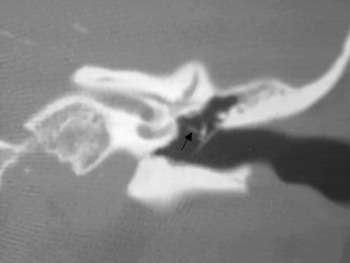
A computed tomography scan was performed prior to the surgery described below, and confirmed displacement of the ossicular prosthesis (Figure 1).
Section of a coronal computed tomography scan of the left temporal bone, showing a displaced prosthesis (arrow).

The patient disliked conventional hearing aids because of the occlusion effect and the stigmatisation associated with conventional air conduction devices.
Surgical technique
We performed the surgery via a left posterior tympanotomy approach. A left cortical mastoidectomy was performed via a postaural incision. The facial recess was opened by careful drilling, with preservation of the chorda tympani and the facial nerve. Intra-operative facial nerve monitoring played an important role in preventing facial nerve injury. The facial recess was gradually enlarged using a diamond burr until the whole stapes suprastructure and the round window niche were visible.
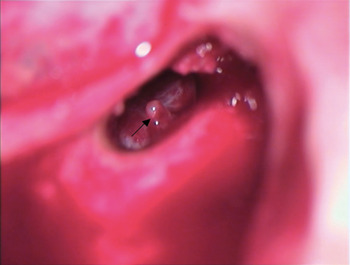
The displaced titanium prosthesis was carefully removed from the left stapes head and then carefully detached from the tympanic membrane undersurface. The tympanic membrane was kept intact throughout the removal of the titanium prosthesis. The entire titanium prosthesis was removed via the posterior tympanotomy. Copious irrigation was required in order to remove the retained blood clot and bone dust. The left stapes head was clearly identified (Figure 2). The normal mobility of the stapes was confirmed by gentle needle palpation and by the presence of a round window reflex. The claw of the floating mass transducer was fashioned so that it could be clipped onto the stapes head using the following steps.
Intra-operative operating microscope photograph showing the left stapes head (arrow) seen via a posterior tympanotomy window.

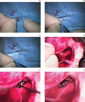
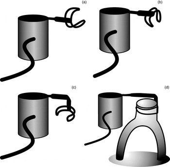
In step one, the floating mass transducer was held with the open end of the claw facing away from the body of the transducer (Figure 3a and Figure 4a). In step two, jeweller's forceps were used to turn the open end of the claw to face downwards (Figure 3b and Figure 4b). In step three, the same forceps were used to turn the open end of the claw to face the body of the floating mass transducer (Figure 3c and 3d and Figure 4c). In step four, the customised floating mass transducer was introduced via the posterior tympanotomy (Figure 3e). In step five, the floating mass transducer was carefully clipped onto the stapes head (Figure 3f and Figure 4d). The stability of the whole arrangement (i.e. the floating mass transducer coupled to the stapes) was confirmed with needle palpation.
Intra-operative operating microscope photographs showing: (a) the floating mass transducer and the position of the open end of the claw (arrow); (b) the open end of the claw fashioned to face downwards, using jeweller's forceps; (c) turning the open end of the claw to face the body of the floating mass transducer, using jeweller's forceps; (d) the final position of the floating mass transducer claw for stapes coupling; (e) introduction of the customised floating mass transducer via the posterior tympanotomy; and (f) the floating mass transducer being coupled to the left stapes (arrow).

Diagrams showing the floating mass transducer: (a) with open claw; (b) with open claw turned downwards; (c) with open claw turned downwards and inwards (to face the body of the floating mass transducer); and (d) the final position of the floating mass transducer after clipping onto the stapes head.

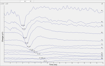
Intra-operative electrocochleography was performed using the GSI Audera evoked potential system (Grason-Stadler, Eden Prairie, Minnesota, USA). Alternating tone pips at 2 kHz were delivered to the implant via a custom-made audio processor. A series of electrocochleography tests were conducted to ensure that the compound action potentials matched the patient's pure tone bone conduction threshold at 2 kHz (Figure 5). If the lowest compound action potential thresholds were close to the bone conduction threshold at 2 kHz, this indicated good coupling of the floating mass transducer to the stapes. If this was not the case, the position of the floating mass transducer placement was adjusted and electrocochleography repeated until a satisfactory floating mass transducer orientation was achieved. The electrocochleography testing procedure was conducted as published in Radeloff and colleagues' 2010 study.Reference Radeloff, Shehata-Dieler, Rak, Scherzed, Tolsdorff and Hagen 6
Electrocochleography result for the presented patient, showing compound action potential recordings in response to 2 kHz tone pip stimuli. Note that the compound action potentials appear a few milliseconds after the onset of stimulation. The lower the intensity, the smaller the compound action potential and the longer the latency. y axis gradations = 5 µV. AP = compound action potential time point in milliseconds; L = intensity level in decibels

Results
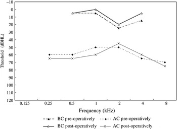
Change in residual hearing was evaluated by comparing the pre-operative unaided air conduction and bone conduction thresholds to the post-operative air conduction and bone conduction thresholds, for audiometric testing frequencies from 250 to 8000 Hz. The results revealed no obvious change at any frequency. Figure 6 presents the pre- and post-operative air and bone conduction thresholds.
Mean air conduction (AC) and bone conduction (BC) thresholds pre- and post-operatively.

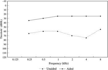
The benefit of aiding was evaluated by comparing the unaided and aided thresholds obtained, using a warble tone in the sound field from 250 to 8000 Hz, three months post-operatively. The non-implanted side was plugged and muffled during testing (Figure 7). Obvious improvements were noted, especially at 1 to 8 kHz. The functional gain (i.e. the difference between unaided and aided thresholds) varied from a minimum of 30 dB to a maximum of 50 dB.
Mean pre-operative (unaided) and three-month post-operative (aided) sound field thresholds from 0.25 to 8 kHz. The non-implanted side was plugged and muffled during testing.

At the time of writing, the patient was using the Vibrant Soundbridge system for 8 hours a day. She reported that the sound quality of the system was natural and clear. She was especially pleased with the way that the Vibrant Soundbridge system had improved her sound localisation and sense of balance.
Discussion
The stapes coupling technique can be performed via either an anterior or posterior tympanotomy approach. In the presented case, we employed a posterior tympanotomy approach, because we believed that this would help prevent extrusion or migration of the conductor link, and because the conductor link could be safely located in the cortical mastoid cavity. In addition, this approach minimises the risk of tympanic membrane perforation. More importantly, the stapes and the round window can easily be seen and approached via a posterior tympanotomy; this facilitates the clipping of the floating mass transducer onto the stapes head and also allows a larger surgical safety margin. The success of the surgical procedure is thus facilitated.
Our experience leads us to believe that the stapes coupling technique provides natural stimulation of the inner ear, resulting in better perceived sound quality compared with the vibroplasty technique. In addition, the stapes coupling technique is less technically demanding. As long as the footplate is mobile and the floating mass transducer is securely placed along the correct axis, as shown in Figure 3(f), a positive outcome is more likely, without significant alteration of residual hearing or raised risk of medical or surgical complication.
Conclusion
The Vibrant Soundbridge system is a partially implantable middle-ear hearing system used to rehabilitate patients with all types of hearing loss. The system contains a floating mass transducer which is fitted either via a round window approach (vibroplasty) or via ossicular chain coupling. We believe that the stapes coupling technique provides natural stimulation to the inner ear and results in a better perceived sound quality than the vibroplasty technique. In addition, the stapes coupling technique is less technically demanding for the surgeon. Thus, we recommend the stapes coupling technique for patients with a functioning stapes remnant.