I. INTRODUCTION
Undesirable and potentially hazardous noise is treated as a type of environmental pollution and can cause a risk to public health.Reference Passchier-Vermeer and Passchier1 Improving the noise absorption, especially at low frequencies, is considered very important in the transport industry and the construction of buildings. Typical sound absorbing materials come in forms of various foams, fibers, boards, mats, perforated metals, aerogels, and others,Reference Arenas and Crocker2,Reference Beranek and Vér3 as a high sound absorption coefficient is usually observed only in porous materials.Reference Crocker4 An empirical equation developed by Delany and Bazley shows that porous materials can absorb sound much better than monolith materials, especially at medium and high frequencies.Reference Kidner and Hansen5,Reference Delany and Bazley6 The typical pore size of a sound absorbing material is below 1 mm, which is much smaller than the wave length of sound.Reference Beranek and Vér3 The sound pressure creates oscillations between air molecules within the porous material. These result in a frictional loss of momentum of these molecules, hence the porous structure reduces the momentum of the propagating high frequency sound wave.Reference Beranek and Vér3 Efficient conduction of heat within a porous composite results in an energy loss for a low frequency sound wave, as the air pressure in the pores undergoes periodic compression and decompression resulting in a change of temperature.Reference Beranek and Vér3 In general, porosity, tortuosity, and air flow resistivity have been claimed as the most important properties for the efficient sound absorption.Reference Cox and D'Antonio7,Reference Fahy8
Recent trends in porous sound-absorbing materials have been reviewed by Arenas and Crocker.Reference Arenas and Crocker2 There are known methods to introduce porosity in materials and improve their sound absorption at low frequencies. For example, Atalla et al.Reference Atalla, Panneton, Sgard and Olny9 found that a hierarchical porosity of macro (porosity in the periodic cylindrical hole fashion) and micro (natural porosity of rock) can be created in mineral rock and thus improve its absorption properties. Cuiyun et al.Reference Cuiyun, Guang, Xinbang and Peisheng10 studied the absorption properties of porous cylindrical zeolites made by sintering zeolites with polymer foam particles and simultaneously burning the polymer to create voids in the structure. It was found that increased porosity improves the sound absorption at frequencies around and below 600 Hz but slightly decreases the absorption at frequencies higher than 1200 Hz; also, thicker samples shifted the absorption toward lower frequencies by approximately 100 Hz per 5-mm increase in thickness. Sodium bicarbonate as a blowing agent was used to prepare porous rubber, which had different pore sizes corresponding to different blowing temperatures.Reference Najib, Ariff, Bakar and Sipaut11 These authors found that the smallest pores (approximately 0.8 mm) had the best sound absorption behavior. Other researchers investigated acoustic behavior of surface-modified polymeric porous microspheres,Reference Ng and Hong12 needle-punctured nonwovens,Reference Yilmaz, Banks-Lee, Powell and Michielsen13 porous road pavements,Reference Olms and Breuer14 microperforated panels,Reference Kang and Brocklesby15 concretes,Reference Kim, Jeon and Lee16 and others.
In this paper, we focus on the sound absorption properties of porous polydimethylsiloxane (PDMS) and porous cement obtained by hydrogel templating. PDMS is a synthetic polymer with a low glass transition temperature. It is available in a range of viscosities and can be cured to produce silicon rubber for a wide range of hi-tech applications, such as microcontact printing and microfluidic device fabrications, and encapsulating material with higher durability than other types of rubber. Cement composites are widely used as building materials; however, significant emissions of carbon dioxide and high energy input in the cement production raise environmental concerns, and this calls for improvements in the sustainability of the build infrastructure.Reference Van Vliet, Pellenq, Buehler, Grossman, Jennings, Ulm and Yip17 Both PDMS and cement can at least solidify partially in less than 24 h, making them an excellent matrix for templating other materials within their matrix. Recently, we developed a novel technique for the preparation of porous materials, where hydrogel beads are templated with materials such as cement or PDMS followed by the removal of water from the hydrogel by evaporation after solidification of the matrix.Reference Rutkevičius, Munusami, Watson, Field, Salt, Stoyanov, Petkov, Mehl and Paunov18 This technique has already allowed us to produce porous composites having reduced density. In the present study, we explore the sound absorption properties of the porous cement and PDMS composites produced at various degrees of porosity using different volume fractions of the hydrogels.
II. EXPERIMENTAL
A. Fabrication of cement and PDMS porous composites
Lafarge extra rapid curing cement was purchased in a local store. Silicon elastomer SYLGARD® 184 (Base oil) and silicon elastomer curing agent SYLGARD® 184 were purchased from Dow Corning GmbH (Wiesbaden, Germany). Polyacrylamide granules as water retaining plant gel (MiracleGel®, The Scotts Company LLC, Marysville, OH) were purchased from a local garden shop. Gellan gum (KELCOGEL LT100) was provided by CP Kelco (Prescot, Merseyside, UK). CaCl2 was purchased from Fisher Scientific (Loughborough, Leicestershire, UK). Fluorescein sodium salt was purchased from Sigma (St. Louis, MO), Rhodamine 6G ? from Acros Organics, New Jersey. Cylindrical molds of thickness of 2 cm and inner diameter of 7.6 cm were cut from teflon in house.
The detailed method for preparation of the composites can be found in the previous publication.Reference Rutkevičius, Munusami, Watson, Field, Salt, Stoyanov, Petkov, Mehl and Paunov18 The scheme of preparation is displayed in Fig. 1. Typically, for a cement composite, a hydrogel was first prepared by adding polyacrylamide granules (12 g) into water (400 cm3) producing 3% hydrogel slurry. After allowing the hydrogel beads to swell for 20 min, CaCl2 (aq, 12.5 cm3, 1 wt%) was added and the mixture was blended for 3 min to produce slurry of microbeads. Then cement slurry was prepared by mixing dry powder of cement with water in a 2.175:1 ratio to produce thick cement slurry. This slurry was then hand-mixed with polyacrylamide hydrogel slurry in various ratios and poured in a cylindrical mold for sound absorption experiments. The samples were allowed to cure at room temperature for 24 h followed by drying at 40 °C for 5 days in a fume hood. Cement slurry-to-hydrogel slurry mixtures at two different volume ratios were prepared and molded at the same conditions as the control sample (100% cement slurry).
Schematic showing hydrogel templating procedure to produce porous cylindrically shaped composites for acoustic testing. The slurries of the matrices are mixed with the hydrogel slurries and molded in cylindrical molds, engineered to match the sample holder in the impedance tube. The evaporation of water from the hydrogel was carried out once the matrix was solidified under ambient temperature and the mold was removed after drying the sample.

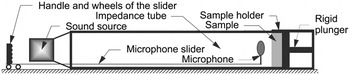
For the PDMS–hydrogel composites, the hydrogel was prepared by adding Gellan gum powder (10 g) to 1000 cm3 water. The resulting mixture was heated in a water bath at 90 °C for about 2 h. After allowing the mixture to cool down to room temperature, the set hydrogel was blended for 3 min to produce slurry of hydrogel microbeads. Simultaneously, PDMS was prepared by mixing the silicon elastomer and curing agent in a 10:1 ratio and then mixing it with the hydrogel slurry in various ratios. The mixture was hand-mixed and degassed under vacuum for 2 h before pouring it into the cylindrical mold. The mixture was allowed to cure for 24 h at room temperature prior to further curing of the sample at 40 °C for 5 days. These composites were then inserted into an acoustic impedance tube and their sound absorption coefficients were analyzed at different sound frequencies. The lower frequency for the test was set to 200 Hz and the upper to 2000 Hz. Data points were taken every 100 Hz for frequencies below 1000 Hz and every 200 Hz for higher frequencies. The tube was made of aluminum, the inner diameter was 76 mm, and the distance from the sound source to the plunger was 3.0 m. An impedance tube with a single microphone was used in this test, where the microphone was attached to a slider (see Fig. 2) according to the published standards.19 Computer-based software analyzed the measured sound pressure amplitude of the combined waves (the sum of the incident wave and the reflected wave). The slider was used to change the position of the microphone within the tube to find the highest (MAX) and the lowest (MIN) sound pressure of the combined waves. The collected p MAX and p MIN pressures were then used to calculate the sound absorption coefficient, α, using Eq. (1):
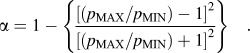 $$\alpha = 1 - \left\{ {{{{{\left[ {\left( {{p_{{\rm{MAX}}}}/{p_{{\rm{MIN}}}}} \right) - 1} \right]}^2}} \over {{{\left[ {\left( {{p_{{\rm{MAX}}}}/{p_{{\rm{MIN}}}}} \right) + 1} \right]}^2}}}} \right\}\quad .$$
Schematic showing impedance tube fitted with a single microphone for sound absorption measurement. The microphone was connected to a computer, which analyzed the signal, and a slider was used to find the highest and the lowest sound pressure spots within the impedance tube.

B. Porosity of the composites
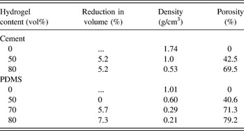
Before and after drying the composites, their sizes and weights were measured. The reduction of the composite volume after evaporating water is shown in Table I and was not significant, but it was still accounted for when calculating the densities of the materials after drying the composites. The porosity of the composites, θ, was calculated using the following formula:
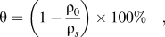 $${\rm{\theta }} = \left( {1 - {{{{\rm{\rho }}_0}} \over {{{\rm{\rho }}_s}}}} \right) \times 100\% \quad ,$$
where ρ0 is the apparent density of the porous composite, calculated from the volume and mass after drying the samples, and ρs is the density of the pure matrix without the hydrogel. The calculated porosity is shown in Table I. As expected, the porosity increased with the initial hydrogel content within the composite. For cement, the porosity was approximately 10% lower than the hydrogel content, whereas for PDMS, the porosity correlated with the hydrogel content very closely. This could be due to the syneresis effect in the cement composites, which is discussed in Sec. II. C.
Porosity, density, and shrinkage of the analyzed cement and PDMS composites.

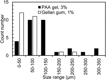
We measured the average hydrogel particle size prior to mixing the slurry with the matrix material by doping the hydrogel with Rhodamine 6G or Fluorescein sodium salt dye and using optical microscopy equipped with a FITC/TRITC filter. The hydrogel particle size distribution is displayed in Fig. 3. The pore size of the final composite should reflect the hydrogel particle size, assuming that the hydrogel size does not change upon mixing with the matrix material and the molding of the sample. The hydrogel bead size was lower for gellan gum gels (mean particle size for gellan gum was found to be 52 μm and 102 μm for PAA).
Graph showing hydrogel bead size distribution for the blended polyacrylamide and gellan gum hydrogel slurries prior to mixing with the matrix material. Sizes were determined by analyzing optical microscope images using computer-assisted software.

C. SEM analysis of the composites
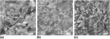
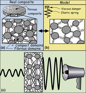
Composites were cut and analyzed with a scanning electron microscope (SEM). The SEM images of the cement composites are displayed in Fig. 4 and those of PDMS composites in Fig. 5. The SEM images show the morphology of the different domains that are present in the porous composites produced from cement–polyacrylamide hydrogel. Fibrous domains (voids) can be observed at the places where the hydrogel beads have been trapped in the solidified cement slurry. The fibrous domains in the porous cement composites resulting from the evaporation of the polyacrylamide hydrogel are bordered by more compact domains of the cement slurry. In addition to the traditional mechanisms of sound absorption mentioned in Sec. I, our working hypothesis for the dissipation of energy involves a more significant deformation of the fibrous domains during exposure to sound, whose elastic and dampening response leads to a more efficient absorption of the sound energy. The latter is possibly due to the friction within the fibrous domains and the adjacent more compact cement particles (Fig. 6).
SEM images of the solidified cement composites after the evaporation of the water phase (a) without hydrogel (0% hydrogel), (b) 50 vol% hydrogel, and (c) with 80 vol% hydrogel. The voids from evaporated hydrogel appear as darker regions and the fibrous domains can be observed within.

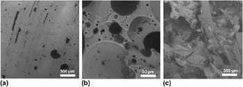
SEM images of the PDMS–hydrogel composite samples after evaporating water, where (a) pure PDMS without the hydrogel, (b) 60 vol% gellan gum hydrogel has been templated within the PDMS composite, and (c) 80 vol% of gellan gum hydrogel was templated within the PDMS composite.

Schematic representation of the hypothesis of the sound energy dissipation by the fibrous domains present within the pores of the composites. (a) Represents the simplified structure of the cement composites, corresponding to the SEM images and (b) is a model structure of the composite, where the compact cement domains are linked with fibrous ones represented as a combination of springs and dampeners, which can absorb the energy of the sound wave and reduce the output amplitude (c).

At high porosity, the compact cement domains [Fig. 6(a)] are bordered by the fibrous domains (pores) [Figs. 6(b) and 6(c)] acting as energy dissipating elements, dampening the amplitude of the incoming sound waves passing through the material. This seems to be most effective when an open-pore structure is formed above the critical volume percentage of the hydrogel, which is approximately 70 vol%.
The SEM images of the porous PDMS sample (Fig. 5) show that the porosity is highly increased when the initial concentration of the hydrogel is increased from 60 to 80%. The sample with lower hydrogel content exhibits a continuous structure of PDMS with a high fraction of voids present, whereas the 80% sample does not show individual voids, as both the hydrogel and PDMS are continuous phases throughout the sample. In the authors’ previous work,Reference Rutkevičius, Munusami, Watson, Field, Salt, Stoyanov, Petkov, Mehl and Paunov18 a rapid decrease in compression strength was shown with increasing porosity. In the present sound absorption experiments, the structure of the 80 vol% hydrogel sample (79% porosity) remained mechanically stable for a range of sound frequencies used. The noncontinuous structures with a lower hydrogel content lead to the hydrogel beads being encapsulated within the sample and excessively long drying times. The cement samples, unlike PDMS, did not show such a clear change between the samples of different hydrogel contents. This could be attributed to the water exchange between the cement slurry and the hydrogel domains occurring to match the osmotic pressure of water in the neighboring environment. We have tackled this effect by adding a small amount of calcium salt into the hydrogel and using a nonionic hydrogel polyacrylamide (PAA), but the effect of the ionic strength of both the matrix and the hydrogel should be investigated in more detail in follow-up studies.
D. Sound absorption of the composites
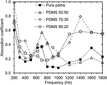
The absorption coefficients as a function of the sound frequency for PDMS and for the cement composites are plotted in Figs. 7 and 8. These data show that the PDMS composites absorb sound well in the lower frequency range. As expected, composites absorb better than the pure PDMS, especially at frequencies >800 Hz, although the 1:1 hydrogel:PDMS sample showed poorer absorption at frequencies above 1000 Hz. Composites with lower hydrogel content formed discontinuous structures where the hydrogel is entrapped in the PDMS matrix and cannot evaporate to form pores. As discussed in the literature, porous materials with an open network of pores show better sound absorption than those with closed pores that do not absorb sound well.Reference Arenas and Crocker2 The 1:1 hydrogel:PDMS sample did not have continuous porosity, and the energy of sound was also not absorbed well by the sample, but mostly reflected back as it was the case for the control sample of pure PDMS. Surprisingly, our porous samples showed high absorption in the low frequency range around and below 300 Hz.
Sound absorption coefficient of the PDMS composites having 0, 50, 70, and 80 vol% hydrogel content as a function of the sound frequency.

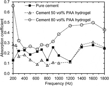
Sound absorption coefficient of pure cement, 50:50 and 80:20 hydrogel:cement composites as a function of the sound frequency.

The cement samples showed a similar trend: the increase in the initial hydrogel content increased the sound absorption, but unlike PDMS, this was observed through a wider frequency range. Since the cured cement slurry is also a microporous material,Reference Alford and Rahman20 the bigger pores created by the templating of the hydrogel domains are likely to increase the ability of the material to absorb the sound energy, as these two networks of pores are interconnected (as shown in the SEM images, Fig. 4). The sound absorption of the 80 vol% hydrogel was also high (up to 0.65) in the low frequency range (200–300 Hz), then decreased through the midfrequencies, and increased again to approximately 0.5 in the higher frequencies (>1000 Hz). We expect that the absorption coefficient of the composites could be increased by reducing the polydispersity of the hydrogel particles and thus forming monodisperse pore-size composites, which could be applied for a specific frequency range. In future studies, we are planning to investigate the effect of the average size and the shape of the hydrogel beads on the sound absorption coefficient, as we expect that this will allow for a better control of the size of the fibrous zones and therefore the dissipation of the sound energy of a specific frequency band.
III. SUMMARY
We have produced porous cement and porous PDMS composites using a hydrogel templating technique and through subsequent evaporation of water from the hydrogels after the complete solidification of the cement or PDMS matrices. The porosity of the PDMS–hydrogel composites closely matched the content of the hydrogel in the samples, whereas in the cement–hydrogel composites, the porosities were up to 10% lower compared with the corresponding hydrogel content. The samples were analyzed using SEM, and fibrous domains were observed in the voids formed from the evaporated hydrogel. We envisage that the fibrous domains within the voids act as sound pressure dampeners, as the sound wave is transferred through the porous cement composite. PDMS composites showed a clear open-pore structure formation in the samples with >70 vol% hydrogel content. Such highly porous PDMS structures have a sound absorption coefficient in the range of 0.45–0.95 for the 70 vol% hydrogel–PDMS sample in the region of 200–400 Hz and of 0.4–0.8 in the region of 1200–2000 Hz. For both PDMS and cement composites, a high sound absorption coefficient in the low frequency range (200–400 Hz) was obtained. This makes these composites potential candidates for sound absorbing materials in sound dampening walls. Further optimization of the sound absorbing properties of these porous composites calls for better control of the pore size. This requires preparation of hydrogel slurries with a uniform size of the hydrogel beads. Such composites would have more uniform pore size distribution, which may lead to better-defined sound absorption in a particular range of frequencies.
ACKNOWLEDGMENTS
M.R. appreciates the Industrial CASE PhD studentship from the EPSRC and Unilever for this study. We also thank the University of Hull for the partial support of this study and Mr Nigel Parkin for the fabrication of the cylindrical molds.