


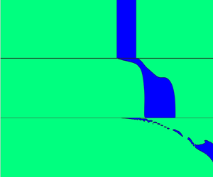



1. Introduction
An understanding of the pressure propagation mechanism and flow restart in a multi-plug gelled pipeline is a challenging scientific and industrial problem. The transportation of waxy crude oil through a pipeline at low-temperature conditions results in gel formation and blockage of the pipeline, which poses a major flow assurance challenge. A small percentage of paraffin wax (i.e. more than 4 %) is sufficient to enhance wax deposition and gelation (Rønningsen Reference Rønningsen1992) in the pipeline. Crude oil is a mixture of hydrocarbons, containing a small percentage of free and dissolved gases. Flow shut down due to a long term or short term emergency or maintenance operations at subsea conditions enhances heat loss from the bulk oil phase into the cold environment. Due to this heat loss, wax crystals grow and form a gel-like structure spanning the entire pipeline. The growth of high aspect ratio, needle-like crystals, and platelets spanning across the gel network, entraps the remaining liquid crude oil (Venkatesan et al. Reference Venkatesan, Nagarajan, Paso, Yi, Sastry and Fogler2005; Paso et al. Reference Paso, Kompalla, Oschmann and Sjöblom2009). During this period, the gel strength increases manifold, preventing flow restart in the gelled pipeline.
An increase in the gel strength depends on the wax concentration, shear history, as well as the thermal history experienced during gelation (Al-Zahrani & Al-Fariss Reference Al-Zahrani and Al-Fariss1998; Zhao et al. Reference Zhao, Kumar, Paso, Ali, Safieva and Sjöblom2012; Mendes, Vinay & Coussot Reference Mendes, Vinay and Coussot2017). Additionally, a thermal shrinkage due to the low temperature and the subsequent segregation of the dissolved gases from bulk oil, results in distributed gas voids, diminishing the gel strength (Hénaut, Vincké & Brucy Reference Hénaut, Vincké and Brucy1999; Dalla, Soares & Siqueira Reference Dalla, Soares and Siqueira2019). Primarily, the distribution of the gas voids depends on the percentage of dissolved gases (Rai, Sarkar & Dalal Reference Rai, Sarkar and Dalal1996) and light hydrocarbons, the rate of cooling, the final temperature and the inclination of the pipeline (Phillips et al. Reference Phillips, Forsdyke, McCracken and Ravenscroft2011a,Reference Phillips, Forsdyke, McCracken and Ravenscroftb; Chala et al. Reference Chala, Sulaiman, Japper-Jaafar, Abdullah and Mokhtar2014). A subsea production pipeline, which follows the Earth's terrain, may have low-pressure points which may accumulate the separated gas phases. Gas pockets can also be formed artificially inside a pipeline to assist the flow restart, by injecting a high-pressure gas into the pipeline (Styring Reference Styring1973), or by replacing a part of the gel in the pipeline by low-pressure gases. Yieldable fluids are introduced to split the gel plug into smaller gel segments to ease the flow-restart process (Stechmeyer Reference Stechmeyer1978). Recently, Lima et al. (Reference Lima, Negrao, Barreira, Rosso, Carvalho and Kroetz2016) proposed the use of pressure relief devices at selected pipeline locations to reduce the peak pressure requirement. These cases can lead to the artificial formation of a multi-plug gel in pipelines transporting crude oil. In the multi-plug gel, an initial pressure propagation may play a more significant role in flow restart as compared to a single plug gel case. The presence of a gas pocket in between the gel plugs may further delay the pressure propagation, resulting in a higher transit pressure gradient. The present work focuses on a detailed analysis of the pressure propagation mechanism and the subsequent gel degradation in the multi-plug gelled pipeline, in the context of flow restart. To the best of our knowledge, the pressure propagation mechanism and its effect on flow restart in a multi-plug gel pipeline have not previously been studied.
The flow-restart mechanism in the gelled pipeline has been studied extensively over the last five decades. In a simplistic model for the estimation of flow-restart pressure  $(P= {2 \tau _{y} L}/{R})$ (Perkins & Turner Reference Perkins and Turner1971; Rønningsen Reference Rønningsen1992), the waxy gel is assumed to be an incompressible, time-independent, yield stress fluid, where,
 $P$ is the restart pressure,
 $\tau _{y}$ is the static yield stress of the waxy gel,
 $L$ is the length of pipe and
 $R$ is the radius of the pipe. Cawkwell & Charles (Reference Cawkwell and Charles1987, Reference Cawkwell and Charles1989) considered a simple one-dimensional (1-D) computational approach to simulate flow restart in a thixotropic and compressible gel material. It predicts that consideration of compressibility significantly lowers the clearing time of the gelled pipeline as compared to the results of Sestak et al. (Reference Sestak, Charles, Cawkwell and Houska1987). Chang, Nguyen & Rønningsen (Reference Chang, Nguyen and Rønningsen1999) developed a time-dependent three yield stress model, which is used by Davidson et al. (Reference Davidson, Nguyen, Chang and Rønningsen2004) and Davidson, Nguyen & Rønningsen (Reference Davidson, Nguyen and Rønningsen2007) in a simplified 1-D analysis to predict the restart operation of the gelled pipeline. A time-dependent Bingham model predicts flow restart with an applied pressure lower than the pressure required to overcome the static yield stress.
To account for the influence of gel compressibility, Vinay, Wachs & Agassant (Reference Vinay, Wachs and Agassant2006) and Vinay, Wachs & Frigaard (Reference Vinay, Wachs and Frigaard2007) developed a robust Bingham rheology based model to predict the pressure propagation mechanism and flow restart. Following the work of Vinay et al. (Reference Vinay, Wachs and Agassant2006, Reference Vinay, Wachs and Frigaard2007), Wachs, Vinay & Frigaard (Reference Wachs, Vinay and Frigaard2009) considered a radial and axial variation in axial velocity and neglected the radial velocity (i.e. 1.5-D restart model). Their analysis considered a time and rate of strain-dependent Herschel Bulkley based thixotropic gel model (Houska Reference Houska1981). They reported that the combined effect of gel compressibility and thixotropy facilitates flow restart. However, their model was unable to capture creep deformation and corresponding gel degradation. At low temperatures, the elastic behaviour or the equivalent high viscosity of gel may also have a prominent effect on its deformation and subsequent failure (de Souza Mendes & Thompson Reference de Souza Mendes and Thompson2013; Kumar, Lawrence & Sjöblom Reference Kumar, Lawrence and Sjöblom2014; de Oliveira & Negrao Reference de Oliveira and Negrao2015; Kumar et al. Reference Kumar, Zhao, Paso, Grimes, Sjöblom and Lawrence2015b, Reference Kumar, Skjæraasen, Hald, Paso and Sjöblom2016). These works capture initial creeping flow by considering either a high initial viscosity or elastic strength of the gel. Due to creeping flow, the deformation in the gel increases, which eventually leads to gel breakage.
An understanding of the role of pressure propagation mechanisms in gel degradation is found to be essential (Borghi et al. Reference Borghi, Correra, Merlini and Carniani2003) for an accurate numerical prediction of flow restart. Various approaches were analysed (Chang et al. Reference Chang, Nguyen and Rønningsen1999; Davidson et al. Reference Davidson, Nguyen, Chang and Rønningsen2004; Vinay et al. Reference Vinay, Wachs and Agassant2006; Wachs et al. Reference Wachs, Vinay and Frigaard2009; Oliveira, Negrão & Franco Reference Oliveira, Negrão and Franco2012; Kumar et al. Reference Kumar, Lawrence and Sjöblom2014, Reference Kumar, Zhao, Paso, Grimes, Sjöblom and Lawrence2015b; Majidi & Ahmadpour Reference Majidi and Ahmadpour2018) for an understanding of the mechanisms of pressure propagation and flow restart in a gelled pipeline. Compressibility, thixotropy and thermal dependency were found to have a profound impact on the pressure propagation mechanisms and gel clearance time (Vinay et al. Reference Vinay, Wachs and Agassant2006; Wachs et al. Reference Wachs, Vinay and Frigaard2009; Kumar, Paso & Sjöblom Reference Kumar, Paso and Sjöblom2015a; Kumar et al. Reference Kumar, Zhao, Paso, Grimes, Sjöblom and Lawrence2015b). An initial assumption was made that pressure propagates in the gel at an infinitely fast speed and instantaneously establishes a uniform pressure gradient (i.e. incompressible gel assumption). Subsequently, the pressure propagation speed is assumed to be the same as the acoustic speed, leading to an almost immediate linear pressure gradient along the pipeline (Chang et al. Reference Chang, Nguyen and Rønningsen1999; Davidson et al. Reference Davidson, Nguyen, Chang and Rønningsen2004, Reference Davidson, Nguyen and Rønningsen2007). In essence, this assumption is valid for the case when there is a negligible pressure attenuation due to low gel strength. However, in the case of compressible gel having significant gel strength, the pressure signal is attenuated due to viscous dissipation and the compressional energy requirement, resulting in a significantly slow propagation of the pressure signal (Kumar et al. Reference Kumar, Zhao, Paso, Grimes, Sjöblom and Lawrence2015b). A nonlinear pressure profile persists for a reasonable time before the pressure profile becomes linear in a strong, compressible gel (Vinay et al. Reference Vinay, Wachs and Agassant2006; Kumar et al. Reference Kumar, Zhao, Paso, Grimes, Sjöblom and Lawrence2015b). In addition to that, the thixotropic nature of the gel plays a crucial role in establishing a pressure profile and eventually in the flow restart (Cawkwell & Charles Reference Cawkwell and Charles1987, Reference Cawkwell and Charles1989; Wachs et al. Reference Wachs, Vinay and Frigaard2009; Kumar et al. Reference Kumar, Lawrence and Sjöblom2014, Reference Kumar, Paso and Sjöblom2015a; de Oliveira & Negrao Reference de Oliveira and Negrao2015; Kumar et al. Reference Kumar, Skjæraasen, Hald, Paso and Sjöblom2016). El-Gendy et al. (Reference El-Gendy, Alcoutlabi, Jemmett, Deo, Magda, Venkatesan and Montesi2012) conducted a flow loop experiment using a model oil and observed a two-step jump in the pressure profile. Recently Kumar et al. (Reference Kumar, Lawrence and Sjöblom2014, Reference Kumar, Zhao, Paso, Grimes, Sjöblom and Lawrence2015b) have explained that the initial pressure propagates as an inertial wave, similar to acoustic wave propagation, which in the absence of the compressible energy requirement becomes linear after a time delay. They have further investigated the effect of gel strength and compressibility on the pressure propagation in gelled oil. The time evolution of the pressure profile shows a high-pressure gradient at the compressional front and a viscous-dissipation-dependent pressure gradient behind the compressional front. The applied pressure continues to deform the gel material in the absence of an adhesive failure, showing a creeping flow behaviour of the gel. The creeping flow eventually results in a gel failure.
It is interesting to note that all the previous numerical models discussed above assume a single plug gel in a horizontal pipeline. To understand the influence of a gas pocket on the flow restart, Davidson et al. (Reference Davidson, Nguyen and Rønningsen2007) analysed a case where a gas pocket separates the gel plugs and this case is referred to as a multi-plug gel. A rheological model, with yield stress referred to as Davidson, Nguyen, Chang and Rønningsen, was used for modelling flow restart in the multi-plug gel. The focus of their work was to study the effect of a gas pocket on the clearance time. In this study, a semi-analytical approach for gel failure analyses the yield front propagation, followed by a compressive deformation. This work did not examine the initial pressure propagation and assumed a constant-pressure gradient. Furthermore, for the analytical study, a uniform axial velocity as a function of the radial position was also assumed. However, a localized strain near the pipe wall facilitates gel failure, and a higher initial pressure gradient creates a localized strain near the wall. In a multi-plug gel case, the gas compression can significantly delay the initial pressure propagation in the second gel plug, which may result in a higher-pressure gradient in the first gel for an extended period. A steeper shear/pressure gradient for an extended period may be sufficient to break the gel depending on the gas pocket volume and the gel rheology. However, to the best of our knowledge, no analysis of initial pressure propagation in a multi-plug gel and its effect on flow restart is available in the current literature. Hence, the present work focuses on the understanding of pressure propagation in a multi-plug pipeline and its effect on the flow-restart processes. Furthermore, it also analyses the impact of gel rheology, the volume of the gas pocket, the position of the gas pocket, the number of gas pockets and the compressibility of the gel on pressure propagation mechanisms and flow-restart processes.
2. Rheological model
The rheological model plays a crucial role in investigating the mechanisms of pressure propagation and flow restart in a multi-plugged pipeline. Below wax appearance temperature, the waxy component starts precipitating and exhibits time, temperature and shear dependent, weakly compressible and thixotropic behaviour. Therefore, the rheological model should be able to capture the phenomena associated with multiple time and length scales. Typically, either a high viscosity, or yield stress, or elasto-viscoplastic based thixotropic model represents the rheological behaviour of a waxy crude gel. Thixotropic properties are considered as a function of time, rate of strain and structure parameter (Davidson et al. Reference Davidson, Nguyen and Rønningsen2007; Wachs et al. Reference Wachs, Vinay and Frigaard2009; de Souza Mendes & Thompson Reference de Souza Mendes and Thompson2013; Kumar et al. Reference Kumar, Lawrence and Sjöblom2014, Reference Kumar, Skjæraasen, Hald, Paso and Sjöblom2016). Barnes & Walters (Reference Barnes and Walters1985) and Barnes (Reference Barnes1999) performed an extensive study of the rheology of different materials which were earlier thought to be yield stress fluids and explained their rheology using a shear-thinning based thixotropic model. Here, we consider the waxy crude oil gel as a viscosity based thixotropic fluid, and combine the variables time and rate of strain to form a single variable, strain (shear deformation in the gel).The strain-based model is shown to be consistent with the experimental observations (Paso et al. Reference Paso, Kompalla, Oschmann and Sjöblom2009; Zhao et al. Reference Zhao, Kumar, Paso, Ali, Safieva and Sjöblom2012) for relatively low values of rate of strain  $({<}10\ \textrm {s}^{-1})$ for their crude oils. During pressure propagation and flow restart, the value of the shear rate remains small. Hence, the gel structure parameter for the flow-restart problem is considered as a point function of shear deformation, which combines the time and rate of strain. Typically, the rheological behaviour of waxy crude has shown the following dependencies:
 \begin{equation} \tau= \tau(\lambda,\dot{\gamma},t), \end{equation}
where  $\tau$,
 $\lambda$,
 $\dot {\gamma }$ and
 $t$ represent shear stress, structural parameter, shear rate and time, respectively. De Kee, Code & Turcotte (Reference De Kee, Code and Turcotte1983) reported that the time and rate of strain-dependent decay of the structure parameter follows the
 $n$th-order kinetic equation
 \begin{equation} \frac{\partial \lambda}{\partial t}= -a \dot{\gamma}^{b}(\lambda-\lambda_{e})^{n},\end{equation}
where  $\lambda$ varies in the range
 $[0,1]$ where
 $\lambda =1$ corresponds to fully structured and
 $\lambda _{e}$ to the equilibrium value (steady-state value) of intact crystal
 $-$crystal bonds and
 $a$,
 $b$ and
 $n$ are gel degradation rate constants. In (2.2),
 $\dot {\gamma }^{b}$ describes the mechanism of gel breakage for a thixotropic waxy crude oil;
 $b=1$ is considered when the shear rate is considered to be responsible for the gel breakage (Mujumdar, Beris & Metzner Reference Mujumdar, Beris and Metzner2002). Using (2.2), Paso et al. (Reference Paso, Kompalla, Oschmann and Sjöblom2009) and Kumar et al. (Reference Kumar, Lawrence and Sjöblom2014) found the structure parameter as a function of strain. Furthermore, it has been shown experimentally that, for a small value of the rate of strain
 $({<}10\ \textrm {s}^{-1})$, gel rheology is a point function of the deformation in the gel (Paso et al. Reference Paso, Kompalla, Oschmann and Sjöblom2009; Zhao et al. Reference Zhao, Kumar, Paso, Ali, Safieva and Sjöblom2012; Kumar et al. Reference Kumar, Lawrence and Sjöblom2014). Furthermore, the viscosity of the gel can be written as a sum of the steady-state viscosity (
 $\mu _{s}$ a constant for a low value of the rate of strain), and gel structure-dependent viscosity (
 $\mu _{g}$ depends on the status of the crystal–crystal network in the gel)
 \begin{equation} \mu_{gel} = \mu_{s} + \mu_{g}(\lambda \rightarrow 1)\lambda(\gamma). \end{equation}
It is to be noted that for a large variation of rate of strain, the steady-state viscosity will depend on the rate of strain (i.e.  $\mu _{s}(\dot {\gamma })$), however, for flow-restart prediction, the
 $\mu _{s}$ variation with
 $\dot {\gamma }$ is neglected. For the first-order gel degradation kinetics following Kumar et al. (Reference Kumar, Lawrence and Sjöblom2014), the gel rheology can be written as
 \begin{equation} \mu_{gel}=\mu_{s}\left[1+m\left(\frac{1-\textrm{e}^{-c_{o} \gamma}}{\gamma}\right)\right],\end{equation}
where,  $m(m=\mu _{g}/\mu _{s}c_{o})$ depends on the structure degradation rate constant
 $c_{o}$, gel viscosity
 $\mu _{g}$ and the viscosity of the crude oil at the fully broken slurry state
 $\mu _{s}$;
 $\gamma$ is the strain in the gel. Here, the strain is a replacement of the time in the thixotropic fluid. Furthermore, it should be noted that, while deriving (2.4), the regelation, after removal of stress, has been neglected. It has been reported (Rønningsen Reference Rønningsen1992; Zhao et al. Reference Zhao, Kumar, Paso, Ali, Safieva and Sjöblom2012; Mendes et al. Reference Mendes, Vinay, Ovarlez and Coussot2015) that after reduction/removal of the applied stress, the extent of regelation in the waxy gel is small. Viscosity based thixotropic model has an advantage over a yield stress or elasto-viscoplastic based model when explaining the mechanisms of pressure propagation, as viscous fluids do not store energy (pressure). Hence, it opens up a possibility of decoupling the compressional and rheological energy storage, which helps in understanding the mechanisms of pressure propagation.
3. Mathematical model
A mathematical model is formulated to simulate initial pressure propagation in the multi-plugged gel, which may or may not lead to flow restart. The model is capable of accurately estimating a time-dependent axial pressure gradient and initial gel deformation, resulting from pressure propagation and subsequent creep flow. In the present study, the gas pocket and gel are considered as separate phases that may reveal new scientific facts. The new scientific understanding can help in finding suitable conditions for an effective flow restart of a gelled pipeline.
This study considers a horizontal multi-plug gelled pipeline as a simplified model. This simplified model can represent either a real multi-plug pipeline situation or an artificially created multi-plug situation, which may help in finding new flow-restart strategies. The analysis assumes no phase change and the absence of any phase mixing during restart operation. The homogeneous gel in the pipeline is assumed to have constant properties initially, and the flow-restart process is considered to be isothermal in nature. Initially, at time  $t = 0$, the interface between the gel and gas plug is assumed to be flat and sharp changes in the phase properties exist across this interface. The viscosity of the gas phase
 $(\mu _{gas})$ is assumed to be constant during the restart process. The acceleration due to gravity is neglected.
3.1. Governing equations
The multi-plug restart model consists of a 2-D axisymmetric cylindrical computation domain  $\varOmega = (0,R) \times (0,L)$ and time interval
 $[0,T]$. Thus, the azimuthal component of velocity is assumed to be zero. Modelling the flow-restart process in a multi-plug gelled pipeline requires a tracking of the two-phase interface, because different phases interact at the interface. The volume of fluid (VOF) method is used to analyse the two-phase flow system (Hirt & Nichols Reference Hirt and Nichols1981). To distinguish between the two phases, the VOF method utilizes the volume fraction function
 $\psi$ as defined by
 \begin{equation} \psi = \left\{\begin{array}{@{}ll} 1, & \text{in gel plug}\\ 0<\psi<1, & \mbox{interface passing through cell}\\ 0 & \mbox{in gas pocket}. \end{array}\right. \end{equation}
Gel density  $\rho _{gel}$ can be written as a function of pressure
 $p$ using the definition of isothermal compressibility
 $(X_{\theta })$,
 \begin{equation} X_{\theta}= \frac{1}{\rho_{gel}}\left(\frac{\partial \rho_{gel}}{\partial p}\right)_{T_{s}}. \end{equation}
Whereas the density of the gas pocket  $\rho _{gas}$ is assumed to follow ideal gas law and is expressed as
 \begin{equation} \rho_{g a s}=\frac{P_{a b s} M}{R_{s} T_{s}}=\frac{\left(p+P_{a t m}\right) M}{R_{s} T_{s}}, \end{equation}
where  $P_{abs}$ is the absolute pressure,
 $P_{atm}$ is the ambient pressure,
 $R_{s}$ is the universal gas constant,
 $M$ is the molar mass and
 $T_{s}$ the temperature.
The transient flow-restart process in a pipeline filled with a compressible multi-plug gel is governed by conservation equations as given below.
Continuity equation
 \begin{equation} \frac{\partial \rho}{\partial t}+\boldsymbol{\nabla} \boldsymbol{\cdot}(\rho \boldsymbol{U})=0, \end{equation}
where  $t$ is time,
 $\boldsymbol {U}$ is the velocity vector and
 $\rho$ is the density of the gel–gas system defined as
 \begin{equation} \rho=\psi \rho_{g e l}+(1-\psi) \rho_{g a s}. \end{equation}
Similarly,  $\mu$ is the viscosity of the gel–gas system defined as
 \begin{equation} \mu=\psi \mu_{g e l}+(1-\psi) \mu_{g a s}. \end{equation}
Momentum equation
 \begin{equation} \rho \frac{\textrm{D}\boldsymbol{U}}{\textrm{D} t}=-\boldsymbol{\nabla} p + \boldsymbol{\nabla} \boldsymbol{\cdot} {\tau}. \end{equation}
In the above equation,  $v$ and
 $u$ are the radial and the axial components of the velocity vector
 $\boldsymbol {U}$ and the stress tensor is given by
 ${\tau }= \mu \dot {\gamma }+(\xi -\frac {2}{3} \mu ) \boldsymbol {\nabla } \boldsymbol {\cdot } \boldsymbol {U}$ where
 $\dot {\gamma }$ is the strain rate tensor defined as
 $\dot {\gamma }=(\boldsymbol {\nabla } \boldsymbol {U}+(\boldsymbol {\nabla }\boldsymbol {U})^{tr})$. The secondary viscosity
 $(\xi )$ represents an irreversible change of state that occurs in the fluid during rapid compression and expansion. However, Vinay et al. (Reference Vinay, Wachs and Agassant2006) have assumed a waxy crude oil to be a Stokes fluid and they have ignored secondary viscosity. Following their assumption, we also consider a secondary viscosity
 $\xi =0$.
To use the rheological model described in (2.4), the value of strain at each grid point needs to be calculated. To evaluate the magnitude of the strain at each grid point, all the strain components need to be calculated first, using a strain evolution equation (3.8) derived by Kumar et al. (Reference Kumar, Skjæraasen, Hald, Paso and Sjöblom2016),
 \begin{equation} \frac{\partial \gamma}{\partial t}+ \boldsymbol{U}\boldsymbol{\cdot} \boldsymbol{\nabla}\gamma - \left(\boldsymbol{\nabla}\boldsymbol{U}\right)^{tr} \boldsymbol{\cdot} \gamma - \gamma \boldsymbol{\cdot} \left(\boldsymbol{\nabla} \boldsymbol{U} \right)=\dot{\gamma}.\end{equation}
Here, a frame invariant time derivative of strain is considered (Morozov & Spagnolie Reference Morozov and Spagnolie2015) and the strain modulus at each grid point is calculated as  $\|\gamma \|=\sqrt {\gamma _{rz}^{2}+\frac {1}{2}(\gamma _{r r}^{2}+\gamma _{\theta \theta }^{2}+\gamma _{z z}^{2})}$. The volume fraction is tracked using the advection equation to know the movement of the gel–gas interface. The volume fraction needed to be modified to account for different compressibilities and different acoustic speeds in the two phases (Denner, Xiao & van Wachem Reference Denner, Xiao and van Wachem2018). Additionally, the volume fraction is also required for calculating the properties of the gel–gas system. After accounting for the different compressibilities and acoustic speeds of the bulk phases, compressive VOF advection becomes
 \begin{equation} \frac{\partial \psi}{\partial t}+\boldsymbol{\nabla} \boldsymbol{\cdot}(\psi \boldsymbol{U})-(K+\psi) \boldsymbol{\nabla} \boldsymbol{\cdot} \boldsymbol{U}=0, \end{equation}
where  $K$ is the material-dependent compressibility factor given by,
 \begin{equation} K=\frac{\psi(1-\psi)[\rho_{g a s} a_{g a s}^{2}-\rho_{gel} a_{gel}^{2}]}{[\psi \rho_{gel} a_{gel}^{2}+(1-\psi) \rho_{g a s} a_{g a s}^{2}]}.\end{equation}
Here,  $a_{gel}$ and
 $a_{gas}$ are the acoustic speed in the gel and the gas medium, respectively. The equations (3.1)–(3.10) need to be solved using the finite volume method that describes pressure propagation mechanisms and flow restart in the multi-plug gelled pipeline.
3.2. Flow geometry and boundary conditions
The flow domain is a 2-D axisymmetric pipe geometry described by the cylindrical coordinates  $(r,z)$ and shown in figure 1. The boundary conditions for the flow domain are given below.
Schematic diagram of the multi-plug gel pipeline and coordinate system.

At the pipe inlet:  $v=\tau _{z z}=0$,
 $p=p_{inlet}$,
 $\gamma =\gamma _{inlet}$.
At the pipe outlet:  $v=\tau _{z z}={\partial \gamma }/{\partial z}=0$,
 $p=p_{outlet}=0$.
At the pipe wall:  $v=u=0$.
Along the axis of symmetry:  $v=\tau _{r z}= {\partial \gamma }/{\partial r}=0$.
The velocity and surface forces are assumed to be continuous at the gel–gas interface. In addition to the above boundary condition, the waxy gel is assumed to be quiescent at surrounding ambient conditions. A secondary fluid is injected at the inlet to apply a constant restart pressure. Furthermore, the secondary fluid is assumed to be the same as the waxy gel in a slurry state represented by the strain at the inlet  $\gamma = 500$.
3.3. Non-dimensionalization and scaling analysis
In order to non-dimensionalize the equations governing the flow-restart process in a low aspect ratio  $(\epsilon = R/L)$ gelled pipeline, we define the axial velocity scale as
 $W_{s}=(P R^{2})/(4\mu _{gel} L)$. Where
 $P = p_{inlet} - p_{outlet}$ is the applied pressure differential across the pipe ends. The radial and axial coordinates are scaled as
 $r=\bar {r}R$ and
 $z=\bar {z}L$, respectively. The other non-dimensional variable are defined as follows:
 \begin{equation} v = \bar{v}\epsilon W_{s}\quad u = \bar{u} W_{s}\quad p=\bar{p}P\quad \mu=\bar{\mu}\mu^{\prime}_{o}\quad t=\bar{t}\sqrt{\delta}(L/W_{s}). \end{equation}
Here, symbol ‘ $\bar {\,}$’ is used to denote non-dimensional variables. In order to capture the fast propagating pressure, time
 $t$ is scaled with the inverse of the square root of the compressibility number
 $\delta = X_{\theta }P$. The viscosity
 $(\mu )$ is scaled with
 $\mu ^{\prime }_{o} = PR/2W_{s}$ and the initial relative viscosity is defined as the ratio of the degradable gel viscosity to the slurry state viscosity i.e.
 $\mu _{r}= \mu _{g}/\mu _{s}$. In addition, the other non-dimensional numbers utilized in the numerical simulation are defined as: the steady-state Reynolds number
 $Re_{ss} = {\rho _{o} R W_{max}}/{\mu _{s}}$; the scaled Reynolds number
 $Re= {\rho R W_{s}}/{(2 \sqrt {\delta } \mu ^{\prime }_{o})}$ , where
 $\rho _{o}$ is the density of crude oil at steady-state condition and
 $W_{s}$ and
 $W_{max}$ are the maximum possible axial velocities in the gel at steady state corresponding to the viscosities of fully structured gel and completely broken gel, respectively. Using the above non-dimensionalization scaling in the governing equation gives,
the continuity equation
 \begin{equation} \frac{\partial \bar{p}}{\partial \bar{t}}+\sqrt{\delta}\left[\bar{v} \frac{\partial \bar{p}}{\partial \bar{r}}+\bar{u} \frac{\partial \bar{p}}{ \partial \bar{z}}\right]+\frac{\sqrt{\delta} \rho}{P}\frac{1}{\left[\psi \rho_{o} X_{\theta} e^{\bar{p} P X_{\theta}}+(1-\psi) \dfrac{M}{R_{s} T_{s}}\right]} \left(\frac{1}{\bar{r}} \frac{\partial \left(\bar{r} \bar{v}\right)}{\partial \bar{r}}+\frac{\partial \bar{u}}{ \partial \bar{z}}\right)=0, \end{equation}
the radial momentum equation
 \begin{equation} \frac{\partial \bar{v}}{\partial \bar{t}}+\sqrt{\delta}\left[\bar{v} \frac{\partial \bar{v}}{\partial \bar{r}}+\bar{u} \frac{\partial \bar{v}}{ \partial \bar{z}}\right] = -\frac{1}{\epsilon^{2} Re} \frac{\partial \bar{p}}{\partial \bar{r}}+\frac{1}{Re \left(2\epsilon\right)} \left[\frac{1}{\bar{r}} \frac{\partial\left(\bar{r}\bar{\tau}_{rr}\right)}{\partial \bar{r}} + \frac{\partial \bar{\tau}_{rz}}{ \partial \bar{z}}-\frac{\bar{\tau}_{\theta\theta}}{\bar{r}}\right], \end{equation}
the axial momentum equation
 \begin{equation} \frac{\partial \bar{u}}{\partial \bar{t}}+\sqrt{\delta}\left[\bar{v} \frac{\partial \bar{u}}{\partial \bar{r}}+\bar{u} \frac{\partial \bar{u}}{ \partial \bar{z}}\right] = -\frac{1}{ Re} \frac{\partial \bar{p}}{ \partial \bar{z}}+\frac{\epsilon}{2 Re}\left[\frac{1}{\bar{r}} \frac{\partial\left(\bar{r}\bar{\tau}_{rz}\right)}{\partial \bar{r}}+\frac{\partial\bar{\tau}_{zz}}{\partial\bar{z}} \right]\end{equation}
and the advection of strain
 \begin{equation} \frac{\partial \bar{\gamma}}{\partial \bar{t}}+ \sqrt{\delta}\left[\bar{\boldsymbol{U}}\boldsymbol{\cdot} \bar{\boldsymbol{\nabla}}\bar{\gamma} - \left(\bar{\boldsymbol{\nabla}} \bar{\boldsymbol{U}}\right)^{tr}\boldsymbol{\cdot} \bar{\gamma} - \bar{\gamma} \boldsymbol{\cdot} \left(\bar{\boldsymbol{\nabla}} \bar{\boldsymbol{U}} \right)\right]=\bar{\dot{\gamma}}\sqrt{\delta}. \end{equation}
4. Numerical simulation
4.1. Discretization scheme
For the discretization of the governing equations, a finite volume method on a staggered grid is utilized. In this scheme, the pressure,  $p$, and the volume fraction function,
 $\psi$, are located at the centre of the computation cell denoted by
 $(i,j)$ whereas the velocity components
 $u$ and
 $v$ are located at the positive vertical and horizontal faces of pressure cell
 $p(i, j)$ denoted by
 $u(i+0.5, j)$ and
 $v(i, j+0.5)$, respectively. For the transient, convective and viscous terms, forward, central and upwind differencing methods are adopted. To determine an accurate interface curvature
 $k$ in the computation cell
 $(i, j)$, the volume fraction
 $\psi$ of eight adjacent computation cells
 $((i\pm 1,j),(i,j \pm 1),(i \pm 1,j \pm 1))$ are utilized.
4.2. Numerical algorithm
A mathematical model to study the pressure propagation mechanisms and transient flow-restart operation in a multi-plugged gelled pipeline requires the solution of the continuity, momentum and advection equations of the volume fraction together with the rheology equations. These equations are solved numerically for the velocity, strain, structure parameter, pressure and volume fraction of the computation cell. To solve these equations, we have developed an in-house finite volume based solver in Fortran 90. The details of the numerical algorithm are given as follows:
Step (I) First initialize  $\bar {u}$,
 $\bar {v}$,
 $\bar {p}$ and
 $\psi$.
Step (II) Time loop  $\bar {t}+1 = (i+1)\varDelta \bar {t}, i \geqslant 1$.
* Initialize  $\bar {u}^{\bar {t}+1}=\bar {u}^{\bar {t}}$,
 $\bar {v}^{\bar {t}+1}=\bar {v}^{\bar {t}}$,
 $\bar {p}^{\bar {t}+1}=\bar {p}^{\bar {t}}$ and
 $\psi ^{\bar {t}+1}=\psi ^{\bar {t}}$.
* Define boundary conditions and initial conditions.
* Solve the advection equation of the volume fraction function for  $i \geqslant 2$ using variables from the previous step.
* Solve the momentum equation by using parameter values from the previous time step  $(\bar {t})$.
* Solve the mass balance equation to find the new pressure field.
* Check convergence, if solution converges go to step II with  $\bar {t} = \bar {t}+1$, otherwise with
 $\bar {t} = \bar {t}$.
Step (III) Obtain data ( $\bar {u}$,
 $\bar {v}$,
 $\bar {p}$ and
 $\psi$).
4.3. Model verification and grid-independence study
The governing equations described in § 3.3 are solved numerically to investigate the mechanisms of pressure propagation in a multi-plug gelled pipeline. Appropriate boundary and initial conditions are applied for the computational geometry, as shown in figure 1. The solution algorithm discussed in § 4.2 is utilized for solving the governing equations. Non-dimensional length scale  $(\bar {r}, \bar {z})$ and time scale
 $\bar {t}$ are utilized for presenting the results. Here, the influence of gas pockets on the pressure propagation mechanisms and flow restart in the multi-plug gelled pipeline is investigated. The effect of gel compressibility and rheology on gel degradation is studied. Furthermore, the effect of gas pocket volumes, sizes, locations and number on the pressure propagation mechanisms and flow restart is also elucidated. Table 1 summarizes the parameters used in the study. In the present study, a constant value of the structure degradation rate constant
 $c_{o} = 100$ is used, unless stated otherwise. The gas pocket volume varies from 2.5 % to 10 % of the pipe volume.
The values of the parameters used in this numerical simulation.

The numerical method discussed in § 4.2 is verified by comparing the time evolution of the pressure profiles obtained in the present study with the earlier results of Kumar et al. (Reference Kumar, Lawrence and Sjöblom2014), and a very good agreement is found (see figure 2). Numerical simulations are performed on a computational domain having a uniform structured mesh in each direction. The numbers of computation cells in the radial and axial directions are denoted by  $n_{r}$ and
 $n_{z}$, respectively. At the beginning of the restart operation (i.e.
 $\bar {t}=0$), the gel is assumed to be stationary. A secondary fluid applies pressure at the inlet. The pressure propagation in a multi-plug gel medium is discussed in terms of non-dimensional terms such as
 $\bar {p} = (p - p_{outlet})/(p_{inlet} - p_{outlet})$ and
 $\bar {t}$. The pressure profile obtained in the first gel plug at different times
 $(\bar {t})$ is compared with a similar time scale utilized in the previous work of Kumar et al. (Reference Kumar, Lawrence and Sjöblom2014). Post-processing analysis done for the same gel strength and compressibility elucidates that the pressure profile exactly matches until it approaches the first gel–gas interface (figure 2). Pressure profiles obtained at
 $\bar {t}=0.2$ and
 $\bar {t}=0.4$ in the multi-plug gel case match the earlier results of the homogeneous gel case. However, as time increases, e.g.
 $\bar {t} \geqslant 0.8$, the pressure profile obtained for the multi-plug gel case starts deviating from the result of the homogenous gel case. High compressibility and low viscosity of the gas pocket limit our comparison only to the first gel plug. Also, variation in the axial velocity along the radial direction for the cases examined above, shown in figure 3, supports our comparison.
Comparison of the time evolution of the pressure profiles in the single plug gel and the multi-plug gel medium with a gas pocket volume of 2.5 %; other parameters  $\delta = 4 \times 10^{-4}$,
 $\mu _r=200$,
 $Re_{ss}=798$ remain the same for both cases. The gel volume is kept the same in both cases.

Comparison of the axial velocity profile at the pipe inlet for a single plug and a multi-plug gel (profile with symbols). (a) Represents the axial velocity profiles before the pressure signal reaches the gel–gas interface, and (b) represents the axial velocity profiles after the pressure signal reaches the gel–gas interface, for  $\delta = 4 \times 10^{-4}$,
 $\mu _r=200$,
 $Re_{ss}=798$ and gas pocket volume 2.5 %.

Two different approaches have been considered by Kumar et al. (Reference Kumar, Zhao, Paso, Grimes, Sjöblom and Lawrence2015b, Reference Kumar, Skjæraasen, Hald, Paso and Sjöblom2016) to evaluate the modulus of the strain tensor in the gel. In the first approach, a material derivative is used to evaluate the absolute value of strain (Kumar et al. Reference Kumar, Zhao, Paso, Grimes, Sjöblom and Lawrence2015b). While the second approach utilizes a frame invariant upper convective time derivative for calculating the evolution of individual components of the strain tensor (Kumar et al. Reference Kumar, Zhao, Paso, Grimes, Sjöblom and Lawrence2015b). Consequently, the modulus of the strain is calculated using the strain tensor, which is further used to determine the state of the gel structure (Kumar et al. Reference Kumar, Skjæraasen, Hald, Paso and Sjöblom2016). However, for small deformations, the upper convective time derivative can be replaced by the material or substantial time derivative (Macosko Reference Macosko1994). Figure 4(a,b) represents a comparison between the strain evolution for these two approaches. It is observed that the strains using these two methods remain similar during pressure propagation. Although, once the gel starts moving and the flow resumes, the strain calculated using the upper convective time derivative predicts a higher value of strain.
The evolution of strain along the pipe length as a function of time, with and without (profile with symbols) upper convective time derivative given for (a) small strain values during initial pressure propagation, and (b) large strain values once the first gel plug starts degrading, in the case of  $\delta = 4 \times 10^{-4}$,
 $\mu _r=200$,
 $Re_{ss}=743.3$ and gas pocket volume 10 %.

The effect of mesh size on the numerical solution is analysed for both the radial and axial directions. First, the effect of mesh refinement in the radial direction is evaluated in terms of the relative error  $\varepsilon _{r}$. The relative error is calculated by taking the ratio of the difference between the values of the analytical solution and the numerical solution to the value obtained in the analytical solution. The radial variation in axial velocity is compared with its corresponding analytical solution. For a fully developed flow, radial variation in the axial velocity is independent of the axial grid sizes
 $(n_{r} \geqslant 20)$. The relative errors present in the axial velocity profile for different mesh sizes in the radial direction are summarized in table 2. Based on the trade-off between the computational time and the relative error associated with mesh refinement,
 $n_{r} =20$ is selected for the numerical calculations.
Mesh refinement effect on the accuracy of the solution.

Similarly, to examine the axial mesh size dependency, the axial pressure gradient is calculated using different axial mesh sizes and compared with the corresponding analytical results. Here, the number of computation cells in the axial direction  $n_{z}$ varies from 100 to 300. Based on the results presented in table 2,
 $n_{z}=200$ is selected for the simulations.
An implicit scheme similar to Vinay et al. (Reference Vinay, Wachs and Agassant2006) and Kumar et al. (Reference Kumar, Zhao, Paso, Grimes, Sjöblom and Lawrence2015b) is used for time integration. An iterative prediction correction approach is used at all time steps. Vinay et al. (Reference Vinay, Wachs and Agassant2006) found that, as the compressibility number decreases, the number of iterations required for the convergence of the solution increases. Whereas Kumar et al. (Reference Kumar, Zhao, Paso, Grimes, Sjöblom and Lawrence2015b) found that, as the compressibility number decreases, the number of iterations required for the convergence of the solution also decreases. This is due to the fact that Kumar et al. (Reference Kumar, Zhao, Paso, Grimes, Sjöblom and Lawrence2015b) uses the compressibility number  $(\delta )$ to rescale time. In the present study, time is rescaled by using the acoustic speed (
 $\propto \sqrt {\delta }$). Here, we want to resolve the time scale for the propagation of acoustic waves. Hence, the number of iterations required for all compressibility numbers remains similar (typically 4 to 9 iteration).
5. Results and discussion
5.1. Effect of gas pocket on the flow-restart mechanism
To illustrate the effect of a gas pocket on the mechanisms of pressure propagation and flow restart in the gelled pipeline, the volume of the gas pocket is taken as 10 % of the total volume. In this simulation, a gel compressibility number of  $\delta = 4 \times 10^{-4}$, initial gel strength of
 $\mu _r=200$ and steady-state Reynolds number
 $Re_{ss}=743.4$ are considered. The pressure is applied at the inlet section of the pipeline using a broken gel (i.e. a Newtonian fluid called the secondary fluid). The time evolution of the pressure profiles for a weakly compressible multi-plug gel is presented in figure 5(a). The pressure profiles obtained at the non-dimensional times
 $\bar {t}=0.2$ and
 $\bar {t}=0.8$ match the results of Vinay et al. (Reference Vinay, Wachs and Agassant2006) and Kumar et al. (Reference Kumar, Lawrence and Sjöblom2014). These curves represent pressure propagation before it reaches the gas pocket. The initial pressure profile has a convex shape, followed by a concave profile. Figure 5(b) shows the time evolution of inlet and outlet flow rates in a multi-plug gel pipeline. A positive increase in the inlet flow rate is observed immediately after the application of pressure. However, the outlet flow rate remains zero until the pressure signal reaches the outlet. The inlet and outlet flow rates for small values of time are given in the inset of figure 5(b), to understand the initial change in the inlet flow and outlet flow rates. Initial changes in the pressure profile, and the gel condition (viscosity) are presented separately in figures 6(a) and 6(b) respectively.
(a) Time evolution of the pressure profile as a function of axial position, (b) time evolution of the inlet and outlet volumetric flow rates for  $\delta = 4 \times 10^{-4}$,
 $\mu _r=200$ and
 $Re_{ss}=743.4$, with a gas pocket volume of 10 % (the position of the gas pocket is located between 0.55 and 0.64 units from the inlet).

(a) Initial time evolution of the pressure profile along the axial direction of the pipe, with details of the pressure propagation in the second gel plug inscribed in the figure. (b) Non-dimensional gel viscosity as a function of axial position near the pipeline wall (profile with symbol), for  $\delta = 4 \times 10^{-4}$,
 $\mu _r=200$ and
 $Re_{ss}=743.4$, while a gas pocket volume of 10 % (the position of the gas pocket is located between 0.55 and 0.64 units from the inlet) is considered.

Pressure profiles at  $\bar {t}=0.2$ and
 $\bar {t}=0.6$ in figure 6(a) demonstrate pressure propagation mechanism in the upstream gel. At non-dimensional time
 $\bar {t}=1.4$, the pressure signal approaches the first gel–gas interface. At this stage, the pressure profile changes into a concave shape. These changes in the pressure profile are similar to those observed in a single plug pressure profile, as reported by Vinay et al. (Reference Vinay, Wachs and Agassant2006) and Kumar et al. (Reference Kumar, Zhao, Paso, Grimes, Sjöblom and Lawrence2015b). The pressure profile changes from convex to concave due to a pressure build-up as pressure propagation halts after encountering a gas pocket, this leads to a sharp pressure gradient between the inlet and the first gel–gas interface (at time
 $\bar {t}=1.4$, figure 6a). A sharp pressure gradient in the first gel plug results in a sudden flow of the first gel plug. This sudden flow of gel in the gas phase is referred to as inertial puncture (Kumar et al. Reference Kumar, Zhao, Paso, Grimes, Sjöblom and Lawrence2015b). Inertial puncture leads to a sudden decrease in the pressure gradient near the end of the first gel plug, as shown in figure 6(a) at time
 $\bar {t}=2.8$. In the present case, a pressure puncture is observed as the gel encounters a more compressible gas, this results in conditions similar to the open-boundary conditions in the case of Kumar et al. (Reference Kumar, Zhao, Paso, Grimes, Sjöblom and Lawrence2015b). In the case of Kumar et al. (Reference Kumar, Zhao, Paso, Grimes, Sjöblom and Lawrence2015b), the incoming pressure signal encounters an open atmosphere condition, which results in a pressure release. However, in the multi-plug case, gas in the gas pocket is compressed continuously by the first gel plug. At this moment, the information regarding the existence of a high compressibility gas pocket travels upstream and continues until
 $\bar {t}=2.8$. During this period, the pressure profile tends to become linear, and the pressure signal travels to the second gel (see figure 6a). The pressure profile becomes linear, as the applied pressure is utilized only for shearing the gel. During the initial signal propagation, the pressure acts against the viscous resistance as well as the compressional resistance. However, after initial signal propagation, viscous dissipation becomes similar throughout the first gel plug. In the absence of a pressure requirement for gel compression, the pressure gradient becomes uniform in the first gel plug. Subsequently, the adjusted pressure signal with the information of a highly compressible gas pocket, reaches the first gel–gas interface at
 $\bar {t} \sim 4.2$. The adjusted pressure signal causes more flow of the gel into the gas pocket. Hence, the pressure in the gas pocket starts increasing (figure 6a at
 $\bar {t}=8$) as an additional flow compresses the gas pocket. Complete compression of the gas pocket requires a significant movement of the first gel plug. This delays pressure build-up in the gas pocket, resulting in a relatively large pressure gradient across the first gel plug. Deformation in the first gel plug intensifies in the presence of a high-pressure gradient. Shear deformation in the first gel plug leads to a reduction in the gel viscosity. Figure 6(b) illustrates the comparison of the gel viscosity
 $(\bar {\mu })$ in a multi-plug gel along the pipe length (near the pipe wall) with the viscosity in the case of a single plug gel. At
 $\bar {t}=0.2$, the gel viscosity distribution in the multi-plug gel matches the case of single plug flow. However, in the presence of a steep pressure gradient in the multi-plug case, the gel starts degrading faster after
 $\bar {t}=1.4$. The difference in the gel viscosity is more evident at times
 $\bar {t}=4$ and
 $\bar {t}=6$. Here, it is worth mentioning that a reduction in gel strength is associated with a higher creep flow. A higher creep flow is observed (axial velocity in figure 3b) in the case of a multi-plug gel as compared to the case of a single plug gel.
The extent of gel degradation in the first gel plug, before pressure propagates to the second gel plug, depends on the volume of the gas pocket. Low viscous resistance of the gas pocket results in a negligible pressure gradient in this region (see figure 5a at  $\bar {t}=14$). The slow compression of the gas pocket continues during pressure propagation to the second gel plug (see figures 5a and 6a). However, the magnitude of the initial pressure remains low in the gas pocket, which increases gradually as the first gel plug compresses the gas pocket. In the second gel plug, the pressure appears to propagate with a constant-pressure gradient (i.e. a linear pressure profile), unlike in the first gel, where the compressional front has a very-high-pressure gradient. The second gel has a linear pressure profile, which is consistent with the experimental results of Borghi et al. (Reference Borghi, Correra, Merlini and Carniani2003). Borghi et al. (Reference Borghi, Correra, Merlini and Carniani2003), in their experimental study, increased the secondary fluid supply gradually at the inlet to increase the applied pressure and observed a linear pressure profile in the gel. Here, the pressure in the gas pocket also increases gradually, and simultaneously it propagates to the second gel plug. A pressure signal propagates in the second gel plug due to a gradual build up of pressure in the gas pocket. Pressure signals in the second gel plug attenuate due to a combined effect of compressibility and viscosity, and a linear pressure profile develops in the second gel (figure 6a). After an initial pressure propagation in the second gel, pressure further increases in the gas pocket; hence, the second gel plug is also compressed gradually in a distributed manner, as shown in figure 5(a) at times
 $\bar {t}=7$,
 $\bar {t}=14$ and
 $\bar {t}=28$. Thus, instead of an instant and sharp pressure gradient in the second gel, a more distributed constant-pressure gradient is established (i.e. a linear pressure profile) even in the presence of a compressional resistance. During this period, a sudden rise in the outflow rate is observed, as shown in figure 5(b) at
 $\bar {t}=16$ to
 $\bar {t}=36$. Axial pressure gradient build-up in the second gel plug results in a decrease in the pressure gradient across the first gel plug. This reduction in the pressure gradient across the first gel plug leads to a decline in the inlet flow rate. However, at later stages, an oscillation is observed in the pressure gradient (convex to concave pressure profile and vice versa), as pressure builds up in the gel and releases due to outlet flow. A uniform axial pressure gradient develops across the pipeline at a time
 $\bar {t}=128$ (figure 5a), representing steady-state operational conditions. At steady-state conditions, the inlet and outlet flow rates coincide (i.e.
 $\bar {t} > 140$ in figure 5b).
Figure 3(b) reveals a higher creeping flow in the case of a multi-plug gel plug as compared to a single plug gel. Higher creeping velocity in a multi-plug gel result in a higher deformation, which decreases the viscous resistance significantly (figure 6b). Figure 6(b) shows the same viscosity in both cases at the initial time  $\bar {t}=0.2$, however, at a later time (
 $\bar {t}=6$), the viscosity in the single plug is observed to be a factor 2 higher as compared to the viscosity in the multi-plug gel case. This reduction of viscous resistance in the multi-plug gel assists a flow restart in the multi-plug gelled pipeline. Figure 7 shows the movement of a gas pocket with time. Figure 7(a) shows an unmoved gas pocket, as the pressure signal does not reach the gas pocket at a time
 $\bar {t}=0.2$. Figures 7(b) to 7(e) show the movement of the gas pocket for higher values of time. By comparing these figures, it is clear that, initially, the gas pocket movement is slow, however, once the gel is degraded, the gas pocket moves faster, resulting in a flow restart. Furthermore, it is noticed that, initially, the gas pocket advects in the axial direction, but later, the gas pocket slowly moves towards the centre of the pipeline. Initially, the gel plug moves in the axial direction as a single plug, resulting in a negligible velocity gradient in the radial direction. Without the radial velocity gradient, the gas pocket also advects in the axial direction. However, after some time (when the gel degrades), a significant shear gradient is observed in the middle part of the gel (see figures 7d and 7e), causing the gas pocket to move towards the centre. Here, a high density fluid (gel) is accelerating towards a low density fluid (gas pocket), resulting in Rayleigh–Taylor instability (Drazin & Reid Reference Drazin and Reid2004). Furthermore, in our case, the ratio of the equivalent gravitational force (the equivalent gravitational force is obtained by balancing it with the pressure gradient across the bubble) to the viscous force varies between 18 and 35.5 (at the time of droplet breakup i.e.
 $\bar {t}=70$ to
 $\bar {t}=100$) and the value of the Eötvös number (i.e. the driving force to surface tension) is very large. A similar bubble breakup was recently explained (Tripathi, Sahu & Govindarajan Reference Tripathi, Sahu and Govindarajan2015) for a ratio of gravitational force to viscous force (i.e. Galilei number)
 $Ga=10$ to 70 and large Eötvös number. In our case, the pressure gradient plays the role of the gravitational force.
Time evolution of multi-plug density contour movement along the pipe length for the case of a gas pocket volume 10 %,  $\delta = 4 \times 10^{-4}$,
 $\mu _r=200$ and
 $Re_{ss}=743.4$; (a)
 $\bar {t}=0.2$, (b)
 $\bar {t}=50$, (c)
 $\bar {t}=70$, (d)
 $\bar {t}=90$ and (e)
 $\bar {t}=120$.

5.2. Effect of gel compressibility on the restart mechanism
The effect of gel compressibility on the pressure propagation mechanism and flow restart in a single plug case has already been studied in earlier works (Davidson et al. Reference Davidson, Nguyen, Chang and Rønningsen2004; Vinay et al. Reference Vinay, Wachs and Agassant2006, Reference Vinay, Wachs and Frigaard2007; Wachs et al. Reference Wachs, Vinay and Frigaard2009; Kumar et al. Reference Kumar, Lawrence and Sjöblom2014, Reference Kumar, Zhao, Paso, Grimes, Sjöblom and Lawrence2015b, Reference Kumar, Skjæraasen, Hald, Paso and Sjöblom2016). These works explain how gel compressibility has a positive effect on the flow restart. In this section, the impact of gel compressibility on flow restart in a multi-plug pipeline is investigated. The gel compressibility number is varied from  $\delta = 4 \times 10^{-3}$ to
 $\delta = 4 \times 10^{-5}$ to analyse the effect of gas compressibility on flow restart, while the gas pocket volume 5 %,
 $Re_{ss}=779.2$ and gel strength
 $\mu _r=200$ are constant. A gas pocket of 5 % volume at a distance of 0.66 units from the inlet is considered. Figures 8(a) and 9(a) show the pressure profiles as a function of axial position at different values of time for gel compressibility numbers of
 $\delta = 4 \times 10^{-3}$ and
 $\delta = 4 \times 10^{-5}$. At the initial time (before the pressure signal reaches the gas pocket), the speed of the pressure front appears to be similar in both cases, as the acoustic velocity scales time. However, as the pressure front approaches the gas pocket, the pressure-front velocity in the case of the low compressibility (figure 9a) decreases significantly. The gel in the first plug moves towards the gas pocket as the applied pressure compresses the first gel plug, but the movement of the gel in the low compressible case is insufficient to build up the pressure in the gas pocket. In the absence of gas pocket compression, a linear pressure profile with a higher-pressure gradient develops in the first gel plug. Gel degrades under a steeper pressure gradient, and this allows the movement of the first gel plug towards the gas pocket. Thus, there is a significant delay in the propagation of the pressure signal in the second gel plug. In the case of higher compressibility (figure 8a), compression of the gel creates a significant gel movement towards the gas pocket, which is capable of compressing the gas pocket. Hence, the pressure front continues to move in the second gel plug without any significant time delay. This is also clear from the outlet flow rate shown in figures 8(b) and 9(b). It is also observed that, in the case of a high compressibility gel, a positive outflow rate is noticed at
 $\bar {t} \sim 4$ (figure 8b), whereas in the case of a low compressibility gel, the positive flow rate is noticed at a time
 $\bar {t} \sim 40$ (figure 9b). However, in dimensional time (real time), positive outlet flow rates are observed at the same time in both the cases (i.e. the ratio of time required for the pressure to reach the outlet in the case of a low compressibility gel to the case of a high compressibility gel
 ${\sim }4/40 \times (\text {ratio of compressibility number})^{1/2}=1$). For both high and low compressibility, the gel shows a sequential high-pressure gradient in both the first and second gel plugs, resulting in a complete gel breakage and an assured flow restart. Furthermore, the flow-restart time computed for both cases is also similar (i.e. dimensional time ratio
 ${\sim }30/300 \times (100)^{1/2}=1$). Therefore, it can be concluded that the overall compressibility is important rather than just the gel compressibility. The overall compressibility in both the cases is similar and is dominated by the gas pocket compressibility.
(a) Time evolution of pressure profile as a function of axial position, (b) time evolution of inlet and outlet volumetric flow rates for  $\delta = 4 \times 10^{-3}$,
 $\mu _r=200$ and
 $Re_{ss}=779.2$, while a gas pocket volume of 5 % (the position of the gas pocket is located between 0.66 and 0.7 units from inlet) is considered.

(a) Time evolution of pressure profile as a function of axial position, (b) time evolution of inlet and outlet volumetric flow rates for  $\delta = 4 \times 10^{-5}$,
 $\mu _r=200$ and
 $Re_{ss}=779.2$, while a gas pocket volume of 5 % (the position of the gas pocket is located between 0.66 and 0.7 units from inlet) is considered.

5.3. Effect of gel strength and pipeline length on flow-restart mechanism
This section discusses the impact of gel strength and pipeline length on the flow restart in a multi-plugged pipeline. A higher value of gel strength results in a higher viscous damping, which slows the pressure-front propagation speed (Kumar et al. Reference Kumar, Zhao, Paso, Grimes, Sjöblom and Lawrence2015b). To analyse the impact of gel strength on the flow restart in a multi-plug pipeline, a compressibility number  $\delta = 4 \times 10^{-4}$,
 $Re_{ss}=743.4$, a gas pocket volume of 10 % and different initial values of gel strength of
 $\mu _r=200$ and
 $\mu _r=20000$ are considered.
Figures 5(a) and 10(a) illustrate the time evolution of pressure profile for the gel strengths  $\mu _r=200$ and
 $\mu _r=20000$, respectively. Comparison of the various pressure profiles obtained in these cases (at
 $\bar {t}=0.2$ and
 $\bar {t}=0.8$) reveal a larger viscous dissipation in the case of higher gel strength, which results in a slower pressure propagation. The pressure propagation in the cases of
 $\mu _r=20\,000$ results in a slow increment of the inlet–outlet flow rates. To demonstrate this, the time evolution of flow rates obtained for the cases mentioned above are shown in figures 5(b) and 10(b). In the case of higher gel strength, a slow movement of the compressional front delays the gas pocket compression. Furthermore, the initial pressure profile in the case of higher gel strength is more convex than the pressure profile in the case of lower gel strength. This leads to a slow compression of the gas pocket, which causes a more delayed pressure transmission in the second gel plug. Without the significant movement of the first gel plug, the gas pocket remains uncompressed. During this period, the pressure profile in the first gel plug changes from a convex to a concave profile. Hence, a large constant-pressure gradient is established in the first gel plug. Under a large pressure gradient, gel degrades, providing a relatively lower viscous resistance. Low viscous resistance allows the movement of the first gel plug towards the gas pocket, building pressure in the gas pocket. As pressure builds up in the gas pocket, it propagates further to the second gel plug. During this period, the inlet flow rate decreases gradually as the pressure acts (distributes) on a larger part of the pipeline. Figure 10(a) illustrates (for
 $\mu _{r}=20\,000$) the development of a large pressure gradient across the second gel plug, as observed from the pressure profile at times
 $\bar {t}=360$ to
 $\bar {t}=800$. The pressure profile at
 $\bar {t}=800$ (in figure 10a) confirms that, at low flow rates, the degraded first gel plug offers a negligible flow resistance, resulting in a high-pressure gradient in the second gel plug. The second gel plug utilizes this high-pressure gradient for gel breakage. Hence, it further confirms that a multi-plug gel uses the applied pressure in a stepwise manner as compared to a single plug, where the applied pressure acts on the entire pipeline.
(a) Time evolution of pressure profile as a function of axial position, (b) time evolution of inlet and outlet volumetric flow rates for  $\delta = 4 \times 10^{-4}$,
 $\mu _r=20\,000$ and
 $Re_{ss}=743.4$, while a gas pocket volume of 10 % (the position of the gas pocket is located between 0.55 and 0.64 units from inlet) is considered.

Furthermore, the outlet flow rate profiles for a compressibility number  $\delta = 4 \times 10^{-4}$ in the case of a single and a multi-plug gel are compared (figure 11). It is found that the pressure signal in a single plug gel case always reaches the outlet faster. However, the effect of the gas pocket on the flow-restart time, for higher gel strength, can be observed from figure 11(a,b). When the gel strength is low, a much faster pressure propagation is observed in the case of a single plug gel as compared to a multi-plug case. However, the flow-restart time remains similar in both cases, as discussed in § 5.1. For higher gel strength, a faster pressure propagation is observed in the case of a single plug gel. Whereas, in the case of a multi-plug gel (see figure 11a,b) having higher gel strength, a faster flow restart is observed. This proves that multi-plug gels can be used for faster flow restart, as the stepwise higher-pressure gradient for smaller but significant periods breaks the gel faster. Stepwise utilization of the applied pressure opens up the possibility of a flow restart in the longer pipe, even with low applied pressure. A higher viscous attenuation, similar to the high gel strength case, is also observed in the case of a longer pipeline. Hence, the multi-plug gel can also assist flow restart in a longer pipeline, the way it assists flow restart in a high gel strength case.
Comparison of the volumetric outlet flow for a single plug and a multi-plug gelled pipeline, for  $\delta = 4 \times 10^{-4}$, and
 $Re_{ss}=743.4$, with gel strengths (a)
 $\mu _r=2000$ and (b)
 $\mu _r=20\,000$.

It is worth mentioning that, in case of shear-thinning based thixotropic model, the viscous dissipation does not depend on the conditional statement  ${\textrm {d}p}/{\textrm {d}z}>{2\tau _{y}}/{R}$, which is the case for yield stress fluids, as explained by Oliveira et al. (Reference Oliveira, Negrão and Franco2012). In our case, the creeping flow observed in the gel is due to the gel's compression. Creeping flow in highly viscous gel causes a significant pressure attenuation, as reported by Kumar et al. (Reference Kumar, Zhao, Paso, Grimes, Sjöblom and Lawrence2015b)
 $({\textrm {d}p}/{\textrm {d}z} \sim \mu ({\textrm {d}^{2}u}/{\textrm {d}r^{2}}))$. A higher pressure attenuation is observed in the case of a strong gel or in cases where the pipelines are longer, as pressure attenuation is proportional to the gel's viscosity. Viscous dissipation does not have much effect on the acoustic propagation in common fluids (e.g. water, oil, etc.). This is due to the fact that the fluid viscosity of common fluids like water, oil, etc., is low and the fluid flow due to compression is small. In the present study, the gel's viscosity is considered to vary in the range of 100 Pa s to 10 000 Pa s, and a similar flow can cause viscous dissipation of 5 to 7 orders of magnitude larger than that in the case of water or oil. Hence, for a highly viscous gel, the pressure attenuation due to viscous dissipation becomes significant.
5.4. Effect of gas pocket locations, sizes and the number of gas pockets
A constant gas pocket volume of 10 %, is placed at different locations to investigate the effect of the relative position of the gas pocket on flow restart. To evaluate the influence of gas pocket location on the flow restart, a gel compressibility number of  $\delta = 4 \times 10^{-4}$, gel strength of
 $\mu _r=200$ and
 $Re_{ss}=743.4$ are considered. Figures 12(a) and 12(b) show the time evolution of the inlet and the outlet flow rates for the gas pockets at three different locations. In cases where the gas pocket location is relatively close to the inlet section of the pipe, a slightly early jump in the inlet flow is observed. This confirms that the gel flow in the first plug creates compression in the gas pocket. Despite an initial rise in the inlet flow rate, the gas pocket location has little effect on the outlet flow rate. A small variation in the outlet flow rate occurs as it approaches steady state owing to the different locations of the gas pocket.
Comparison of (a) inlet flow rate, and (b) outlet flow rate for a gas pocket located at different axial positions for  $\delta = 4 \times 10^{-4}$,
 $\mu _r=200$ and
 $Re_{ss}=743.4$, while a gas pocket volume of 10 % is considered.

Furthermore, in cases where the gas pocket is located closer to the inlet, a pressure larger than the applied pressure is observed. This rise in pressure for small periods is considered to be due to the interaction between the forward (due to applied pressure) and backward (due to gas expansion) moving pressure waves. The effect of gas expansion on the magnitude of the incoming pressure signal appears to be insignificant in cases where the gas pockets are further away from the inlet. This is because the pressure signal initiated by gas expansion attenuates as it travels through the gel.
Here, an analysis of the impact of gas pocket volume on flow restart is done, by considering a gel compressibility number and a gel strength of  $\delta = 4 \times 10^{-4}$ and
 $\mu _r=200$ respectively. The ratio of gas pocket volume to total volume is varied from 2.5 % to 10 % while keeping the gel resistance constant. A gas pocket is considered (i.e. the first gel–gas interface) at a distance of 0.54 units from the inlet section of the pipe. Figures 5(a,b), 13(a,b) and 14(a,b) show the evolution of pressure profiles and flow rate profiles for various percentages of the gas pocket volume. The figures show a longer delay in gel flow from the outlet in the case of a multi-plug pipe. Despite this, the multi-plug pipeline leads to the early commencement of flow. However, the effect of the gas pocket on flow restart is expected to be more prominent for longer pipelines or stronger gels.
(a) Time evolution of pressure profile as a function of axial position, (b) time evolution of inlet and outlet volumetric flow rates for  $\delta = 4 \times 10^{-4}$,
 $\mu _r=200$ and
 $Re_{ss}=798$, while a gas pocket volume of 2.5 % (the position of the gas pocket is located between 0.58 and 0.605 units from inlet) is considered.

(a) Time evolution of pressure profile as a function of axial position, (b) time evolution of inlet and outlet volumetric flow rates for  $\delta = 4 \times 10^{-4}$,
 $\mu _r=200$ and
 $Re_{ss}=779.2$, while a gas pocket volume of 5 % (the position of the gas pocket is located between 0.58 and 0.63 units from inlet) is considered.

It is also interesting to note the effect of multiple gas pockets on the flow restart. To accomplish this, a high gel compressibility number of  $\delta = 4 \times 10^{-3}$ and a gel strength
 $\mu _{r}=2000$ is considered. Figure 15(a) illustrates the time evolution of the pressure profile in a gelled oil pipeline with multiple gas pockets. Figure 15(b) shows a comparison between the outlet flow rates of a single gas pocket and multiple gas pockets. For this comparison, the case of three gel plugs separated by two gas pockets of volume 5 % each, located at a distance of 0.45 and 0.68 units from the inlet, is considered. In the case of a single gas pocket, a volume of 10 % located at 0.55 units from the inlet is considered. Pressure profiles obtained at
 $\bar {t}=20$ and
 $\bar {t}=28$ represent the sequential movement of a high-pressure gradient from the second gel plug to the third gel plug. This sequential movement of pressure gradient helps in flow restart in a clogged pipeline. As pressure is utilized sequentially, even a low pressure can restart flow in the clogged pipeline.
(a) Time evolution of pressure profiles along the axial direction, (b) comparison of the time evolution of volumetric outlet flow rate in the 2-gel plug and 3-gel plug pipelines for  $\delta = 4 \times 10^{-3}$,
 $\mu _r=2000$ and
 $Re_{ss}=743.4$. In the case of single gas pocket a volume of 10 % located at 0.55 units from inlet is considered while in the 3-gel plug two gas pockets of 5 % volume each located at a distance of 0.45 and 0.68 units from the inlet are considered.

The effect of the gel structure degradation rate constant  $c_{o}$ and steady-state Reynolds number
 $Re_{ss}$ on the pressure propagation mechanisms and flow-restart time in a single plug gel were analysed by Kumar et al. (Reference Kumar, Zhao, Paso, Grimes, Sjöblom and Lawrence2015b). The gel structure degradation rate constant
 $c_{o}$ does not play any role in the pressure propagation speed for realistic compressibility numbers. Figure 16 shows that flow restart becomes faster for higher values of
 $c_{o}$. Similarly, an increase in the steady-state Reynolds number
 $Re_{ss}$ makes flow restart faster, whereas a decrease in the
 $Re_{ss}$ value increases the flow-restart time. These parameters play a similar role in the case of a multi-plug gel.
Effect of the gel structure degradation rate constant  $c_{o}$ on pressure propagation mechanisms for
 $\delta = 4 \times 10^{-4}$,
 $\mu _r=200$ and
 $Re_{ss}=743.4$, while a gas pocket volume of 10 % (the position of the gas pocket is located between 0.55 and 0.64 units from inlet) is considered.

6. Conclusions
To successfully restart the flow in a clogged pipeline, usually, high pressure is applied along the pipeline to overcome the gel resistance. This paper analyses flow restart in pipelines filled with multi-plug gel (formed naturally or artificially), separated by gas pockets. The initial pressure build-up, the pressure propagation (compressional front propagation) and its attenuations due to compressibility and viscous resistance are numerically investigated, to understand the transient behaviour of pressure propagation and flow restart. The transient process of flow restart is analysed by solving the mass and the momentum balance equations together with strain-dependent constitutive relation and VOF equations.
The presence of a gas pocket delays the pressure propagation in a weakly compressible gel due to complex interactions at the gel–gas interface. This delay in pressure propagation depends on the gel strength, the gas pocket volume and the gel compressibility. However, the delay in pressure propagation results in the development of a high-pressure gradient across the first gel plug, which triggers the process of gel degradation. The degraded gel moves towards the gas pocket. The movement of the first gel plug into the gas pocket compresses the gas pocket. Compressed gas pockets apply a high pressure to the second gel plug. By the time the gas pocket is compressed and the pressure signal propagates in the second gel plug, the first gel plug has degraded significantly. The degraded first gel plug offers little resistance, allowing a substantial axial pressure gradient along with the second gel plug. The degraded gel and the gas pocket provide a weak resistance to the applied pressure. Due to this weak resistance in the first gel, the applied pressure transfers to the second gel without any significant attenuation, creating a high-pressure gradient in the second gel. The gel under a high-pressure gradient degrades faster again, resulting in an early flow restart. Sequential gel degradation in each plug proves that the multi-plug gel could be fractured sequentially, and the complete applied pressure can be utilized by each of the plugs to degrade the gel. Thus, the results obtained from the multi-plug pipeline simulation can be used for a more reliable and realistic flow assurance mitigation.
Furthermore, it is shown that the flow restart depends on the overall compressibility of the system rather than gel compressibility. The overall compressibility is dominated (for some industrially relevant compressibility cases) by the gas pocket compressibility, and hence the gel compressibility plays an insignificant role in the flow restart in a multi-plug gelled pipeline. However, if gas compressibility is not encountered in the initial part of the gel, then the applied pressure will be linearly distributed over a longer distance (i.e. between the inlet and first gel–gas interface). This reduces the pressure gradient and gel degradation. Hence, the subsequent flow restart will be hindered.
During pressure propagation and flow restart, a coupling between the applied pressure and the pressure stored and released by the gas pocket is illustrated in our studies. The pressure signal reaches the gas pocket, and subsequently, compressional energy (pressure) is stored in the gas pocket, the storage of compressional energy continues as the pressure signal reaches the outlet. The information of the gas pocket reaches the inlet, and the inlet flow adjusts accordingly. The information of an open boundary reaches the gas pocket, and the gas pocket expands and interacts with the applied pressure. A pressure signal from the inlet, with information of gas pocket and open boundary conditions, reaches the gas pocket, further compressing the gas pocket. These interactions result in a change in the nature of the pressure profile from convex to concave and vice versa before a constant-pressure gradient is established and the flow resumes.
Declaration of interests
The authors report no conflict of interest.


 Open access

