I. INTRODUCTION
Air-cathode microbial fuel cells (MFCs) can recover wasted energy that is stored in organic matters in wastewater for generation of bioelectricity, and represent a promising solution for energy sustainability.Reference Logan1–Reference Chang, Huang, Fu, Liao and Zhu6 Yet, noble metal catalysts such as platinum nanoparticles (Pt NPs) and Pt-based metal alloys are typically required to promote the oxygen reduction reaction (ORR) occurred at cathode.Reference Rismani-Yazdi, Carver, Christy and Tuovinen7 These noble metal catalysts are expensive and often suffer from time-dependent drift and CO deactivation,Reference Yu and Ye8,Reference Winter and Brodd9 which limit the scalability and practicality of MFCs.Reference Bajracharya, ElMekawy, Srikanth, Pant, Scott and Yu10
Enormous efforts have been devoted to develop alternatives to Pt-based catalysts for MFCs.Reference Gong, You, Wang, Zhang, Gan and Ren11–Reference Huang, Zhu, Yang, Zhang, Wu and Dang13 For example, nonprecious metal NPs, such as metal oxidesReference Yan, Tong, Zhang, Han, Wang, Jin, Qin and Guo14 and transition metal macrocyclic compoundsReference Guo, Zhang, Wu and Sun15 have been studied for ORR. Khilari et al. reported the use of manganese cobaltite (MnCo2O4) nanorods and polypyrrole (PPy) as an ORR composite catalyst.Reference Khilari, Pandit, Das and Pradhan16 The MFC equipped with this in situ-synthesized composite achieved a maximum volumetric power density of 6.11 W/m3. Recently, low cost carbon materials, such as activated carbon (AC),Reference Zhang, Pant and Logan17 AC nanofiber,Reference Ghasemi, Shahgaldi, Ismail, Kim, Yaakob and Daud18 carbon nanotube,Reference Gong, Du, Xia, Durstock and Dai19,Reference Feng, Yan, Chen and Wang20 and polypyrrole/carbon black compositeReference Yuan, Zhou and Zhuang21 have attracted a lot of attention. Among them, AC-based catalysts are particularly promising because of their outstanding electrochemical stability and cost effectiveness.Reference Zhang, Pant and Logan17,Reference Zhang, Wen, Ci, Mao, Chen and He22–Reference Cheng and Wu25 In a previous study, the AC catalyst showed an excellent catalytic performance for ORR in MFCs, and was even comparable to the performance of Pt/C catalyst during a long-term operation. AC was cold-pressed with polytetrafluoroethylene (PTFE) as a binder onto a piece of Ni mesh at 150 bar. The maximum power density of 1220 mW/m2 was obtained for MFCs with this AC air-cathode.Reference Yuan, Zhou and Zhuang21
However, the catalytic performance of AC is still limited by its poor electrical conductivity and relatively small number of ORR catalytic areas.Reference Zhang, Xia, Ivanov, Huang and Logan26 A number of approaches have been demonstrated to improve the catalytic performance of AC, such as adding the nitrogen-containing functional groups,Reference Zhang, Wen, Ci, Mao, Chen and He22,Reference Watson, Delgado and Logan23 pyrolyzing AC by iron ethylenediaminetetraacetic acid,Reference Xia, Zhang, Zhang, Liang, Huang and Logan24 tailoring the electrical conductivity by blending carbon blackReference Zhang, Xia, Ivanov, Huang and Logan26 and using metal meshes as current collectors.Reference Cheng and Wu25 These methods have been primarily focused on increasing the number of ORR active areas by adding other functional groups or improving the electrical conductivity. Nevertheless, the catalytic performance of the previously reported AC catalysts still has not satisfied the need for large-scale MFCs.Reference Alvarez-Gallego, Dominguez-Benetton, Pant, Diels, Vanbroekhoven, Genné and Vermeiren27 It is highly desirable to develop a new method for improving the catalytic performance of AC.
Here we reported a new design of air-cathode involving a three dimensional (3D) reduced graphene oxide (rGO) scaffold coated with AC (denoted as rGO-AC). The incorporation of graphene sheets enlarged the electrode surface area and provided more active areas for ORR.Reference Zhu and Dong28 The MFC device with this rGO-AC air-cathode achieved an outstanding power density of 2.25 ± 0.05 W/m2, which was substantially higher than the values reported for MFC devices with plain AC air-cathodes.Reference Cheng and Wu25,Reference Zhang, Xia, Ivanov, Huang and Logan26,Reference Qu, Liu, Baek and Dai29,Reference Zhang, Cheng, Pant, Bogaert and Logan30
II. EXPERIMENTAL
A. Fabrication of rGO-AC air-cathode
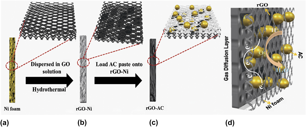
The fabrication process of rGO-AC air-cathode is illustrated in Figs. 1(a)–1(c). Graphene oxide (GO) solution was first prepared according to a method published elsewhere.Reference Wang, Wang, Ling, Qian, Song, Lu, Chen, Tong and Li31 The concentration of GO solution was ∼1 mg/mL. A plain Ni foam substrate [Fig. 1(a)] was placed into a 25 mL autoclave with Teflon liner and filled with the GO solution. The autoclave was heated at 120 °C for 5 h and then cooled down at room temperature. Ni foam was removed from the autoclave, washed with de-ionized (DI) water and then air dried. The Ni foam was uniformly covered by graphene after repeating the above deposition process three times [Fig. 1(b)]. AC catalysts were deposited onto the rGO coated Ni foam using brushing method.Reference Cheng, Liu and Logan32 Briefly, 1 g AC and 5 g Nafion solutions (5 wt%) were mixed with 56 mL ethanol in a beaker. Then the solution mixture was sonicated for 15 min to form a paste. The paste was brushed on one side of cathode and dried at 80 °C in an oven. The AC loading (14, 28, 35, 42 mg/cm2) was controlled by varying the number of brushing process [Fig. 1(c)]. To facilitate oxygen diffusion, the other side of cathode was coated with four diffusion layers of hydrophobic PTFE using a previously reported method.Reference Liu and Logan33 The working principle of rGO-AC air-cathodes is illustrated in Fig. 1(d). The electrons and protons are generated from the decomposition of organic matters via bacterial metabolism at anode. Oxygen (from air) can diffuse into the porous cathode and react with electrons and protons to form water (four-electron pathway) or hydrogen peroxide (two-electron pathway). A previous study found that the optimal loading of AC was ∼42 mg/cm2.Reference Wei, Tokash, Chen, Hickner and Logan34 Therefore, we prepared a control cathode with AC (∼42 mg/cm2) deposited on a plain Ni foam for comparison.
(a–c) Schematic illustration of the fabrication process of rGO-AC cathode. Ni foam was hydrothermally treated in GO solution to obtain rGO-coated Ni foam. AC, Nafion, and ethanol were mixed at a ratio 9:4:1 to form a paste, which was brushed onto the rGO-coated Ni foam. (d) Schematic diagram of rGO-AC cathode.

B. Electrochemical characterizations
Electrochemical analyses, including chronoamperometry (CA), Tafel test and rotating ring disk electrode (RRDE) test, were carried out with a CHI 660D electrochemical station (Chenhua Instruments, Shanghai, China). Both CA and Tafel plots were collected in a three-electrode electrolytic cell with 50 mM phosphate buffer solution (PBS) as electrolyte. Air-cathodes were used as working electrodes with the oxygen diffusion layer facing the air. An Ag/AgCl electrode (saturated KCl, +0.197 V versus SHE) and a Pt plate (99.99%, 1 cm2) were used as reference and counter electrode, respectively.
In CA measurements, the reactor was first operated in an open circuit mode to reach a stable state, and then applied by different voltages (0.2, 0.1, 0, −0.1, −0.2 V) in a stepwise manner. In Tafel test, overpotential from 0 to 0.1 V was measured at a sweep rate of 1 mV/s. The value of exchange current density (j 0) can be obtained from Tafel equation [Eq. (1)] according to the intercept of y-axis:
 $$\log \left| j \right| = \log {j_0} + \left( {{{\beta nF} \mathord{\left/ {\vphantom {{\beta nF} {2.303RT}}} \right. \kern-\nulldelimiterspace} {2.303RT}}} \right)\left| \eta \right|\quad ,$$
where j is the measured current density, j 0 exchange current density, β electron transfer coefficient for reductive reaction, n number of electrons transferred, F Faraday’s constant, R gas constant, T temperature, and η ORR overpotential. For RRDE tests, rotating (Pt) ring-(glassy-carbon) disk electrode was selected as the working electrode. Catalyst ink was prepared by mixing 0.4 mg catalyst powder (plain AC, or rGO-AC powder) and 1.6 mg carbon black (XC-72) with 4 µL Nafion solutions, followed by ultrasonic mixing with 0.4 mL ethanol. 20 µL catalyst inks were added drop wise onto the ring disk electrode and dried under nitrogen atmosphere. Before RRDE measurement, 3 µL 2 wt% Nafion solutions were added to samples as extra binders.
C. Material characterization
The scanning electron microscope (SEM) images of air-cathode materials were collected by a field-emission SEM (Hitachi S4800 Π, Hitachi, Tokyo, Japan). The specific surface areas of plain AC and rGO-AC were identified by surface area and porosimetry analyzer (ASAP 2020, Micromeritics, Norcross, Georgia). The Brunauer–Emmett–Teller (BET) measurements were performed using nitrogen adsorption and desorption isotherms at 77.3 K. Pore width–volume plots were analyzed according to the density functional theory (DFT). To further identify the electrochemical active surface area, cyclic voltammograms at different scan rates were collected and reciprocal of areal capacitance (1/C) against square root of scan rate (v 1/2) were plotted as previously mentioned.Reference Sharma, Bajracharya, Gildemyn, Patil, Alvarez-Gallego, Pant, Rabaey and Dominguez-Benetton35
D. MFC setup
A 28 mL single-chamber MFC device was constructed via the assembly of 3D rGO-coated Ni foam anode (denoted as rGO-Ni)Reference Wang, Wang, Ling, Qian, Song, Lu, Chen, Tong and Li31 and rGO-AC (or plain AC) coated Ni foam cathode. All MFCs were inoculated from the culture enriched with Shewanella oneidensis MR-1 (ATCC-700550, ATCC, Manassas, Virginia). Bacteria were cultured in an incubator shaker contained 30 g/L trypticase soy broth (TSB, BD Biosciences, San Jose, CA) medium with shaking at 150 rpm at a constant temperature (30 ± 1 °C).Reference Wang, Wang, Ling, Qian, Song, Lu, Chen, Tong and Li31 To maintain the bacterial metabolism environment neutral (pH value ∼7.0), the nutrient were further diluted in 50 mM PBS that contained 9.1 g/L K2HPO4 and 1.28 g/L KH2PO4.Reference Wang, Wang, Ling, Qian, Song, Lu, Chen, Tong and Li31 MFCs were inoculated under the external resistance of 500 Ω and voltage (U) was recorded using a data acquisition system (2700 Keithley, Keithley Instruments, Solon, Ohio) every 10 s. Once the voltage dropped to the baseline, i.e., 50 mV, reactors were refreshed by adding fresh TSB medium.
Cell performance was tested after successful inoculation by varying the external resistance (R) from 3900 to 10 Ω. Current (I) was calculated according to the ohm’s law: I = U/R and power (P) was calculated based on the equation: P = U × I. Both the current density and power density were normalized to the electrode surface area (∼5 cm2). All MFC measurements were repeated three times to ensure good reproducibility.
The electrochemical impedance spectroscopy (EIS) was carried out in a two-electrode configuration at a constant voltage of 0.1 V over a frequency range of 10,000–0.01 Hz with a perturbation of 10 mV. EIS data was analyzed using ZSimpwin software (Princeton Applied Research, Berwyn, Pennsylvania) by fitting the spectra with an equivalent electric circuit.
III. RESULTS AND DISCUSSION
A. Structural analyses of rGO-AC catalysts
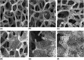
The structures of plain Ni and AC-loaded Ni foams were characterized by SEM. The plain Ni foam showed a smooth surface [Fig. 2(a)]. Upon refluxing in rGO solution, the Ni foam was gradually covered by graphene sheets [Fig. 2(b)]. Then, rGO-AC electrodes with different AC loadings were prepared by controlled variation of the number of loading cycles [Figs. 2(c)–2(f)]. By repeating the loading process, the thickness and roughness of the air-cathodes increased with AC loading. Meanwhile, some of the pores were blocked when large amount of AC (42 mg/cm2) were coated on the scaffold [Fig. 2(f)]. The blockage of pores may affect the oxygen diffusion efficiency and limit the catalytic performance.Reference Ren, Zhang, Tran and Read36
SEM images showing the surface morphology of (a) plain Ni foam; (b) rGO-Ni (no AC); (c–f) rGO-AC (14, 28, 35, 42 mg/cm2).

N2 adsorption/desorption measurements were performed to investigate the specific surface area and pore distribution of these electrodes. The pore-diameter detection range of this measurement is from 0.35 to 500 nm. Fig. S1(a) shows the type-IV curves of isotherms obtained from these samples that are consistent with the curves reported for AC-based catalysts.Reference Dong, Yu and Wang37,Reference Dong, Yu, Wang, Zhou and Feng38 Pore characteristics of different catalysts are summarized in Table S1. The rGO-AC sample with the highest AC loading (42 mg/cm2) exhibited the largest BET specific surface area of 313.41 m2/g, which was almost 2-folds higher than that of the plain AC (157.81 m2/g). Nevertheless the macro-pores (pore size ∼ hundreds of micrometers) began to be blocked with increasing the mass loading of AC, rGO-AC sample with the highest loading (42 mg/cm2) still exhibited the largest specific surface area. One side, the largest BET surface area is related to the increased amount of micro-pores from AC. On the other side, it is believed to be contributed from graphene sheets, which have a high theoretical surface area of 2630 m2/g.Reference Zhu, Zhu, Murali, Stoller and Ruoff39
In the plot of pore diameter as a function of incremental pore volume [Fig. S1(b)], all rGO-AC catalysts exhibited a peak centered at around 2.5 nm, while this peak was not observed for plain AC. The average pore diameter was drastically decreased from 18.22 to 3.22 nm with the increasing amount of AC (Table S1). It confirms that the amount of micro-pores gradually increases after blending the AC with graphene sheets. The high ratio of micro-/meso-pores in AC catalysts is favorable for ORR and can further boost catalytic activity.Reference Dong, Yu and Wang37 Meanwhile, the broad distribution of pore diameters can also facilitate the ion transport and charge transfer during ORR.
B. MFC performance
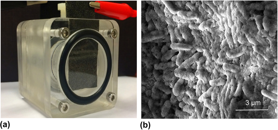
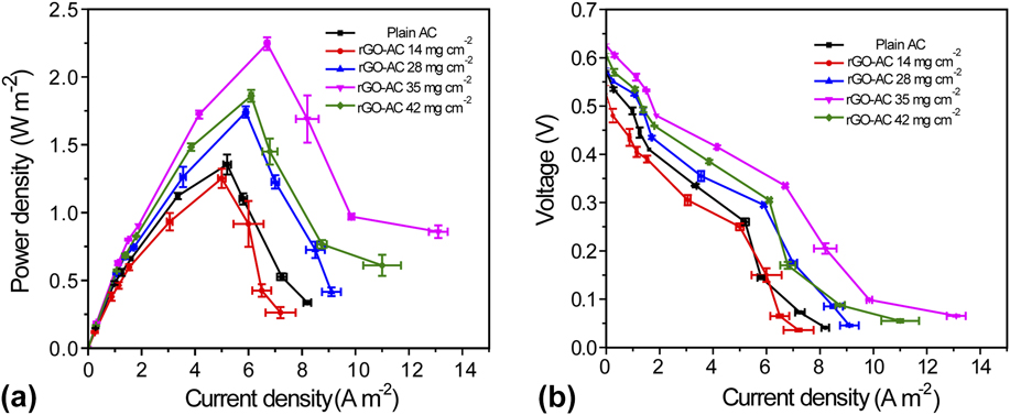
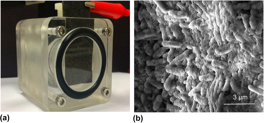
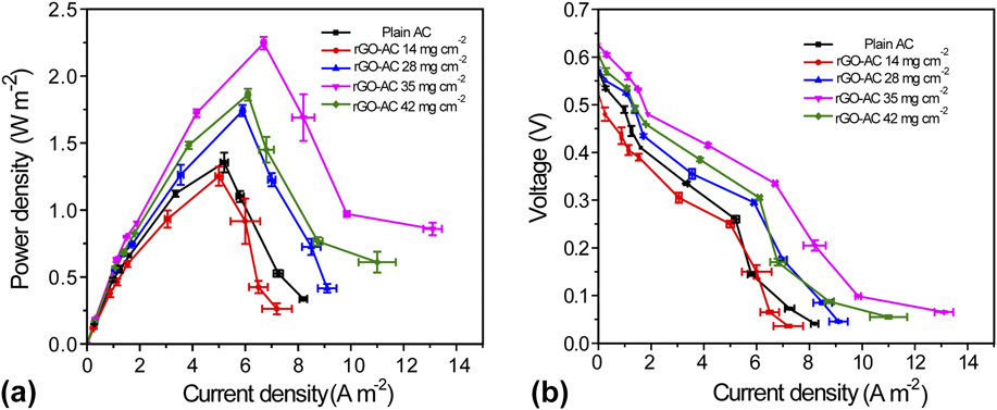
The performance of MFCs equipped with these rGO-AC air-cathodes was tested in a single-chamber device [Fig. 3(a)]. Three-dimensional rGO-Ni was used as the bio-anode. After repeating the inoculation process for three cycles in a batch-mode, S. oneidensis MR-1 cells were successfully colonized on the electrodes and formed a compact biofilm as the SEM image indicated [Fig. 3(b)]. The dense bacterial film on the anodic surface ensures stable performance of bio-catalyzed reactions on the bio-anode side. Figure 4 shows the power density and polarization curves collected from different cathodes. Among them, the MFC with rGO-AC (35 mg/cm2) cathode achieved the best performance with the highest maximum power density of 2.25 ± 0.05 W/m2 at a current density of 6.70 ± 0.07 A/m2, which was 66.7% higher than that of plain AC cathode (1.35 ± 0.07 W/m2). When the MFCs were connected to a resistor of 10 Ω, the rGO-AC (35 mg/cm2) MFC generated the highest current density of 13.1 ± 0.45 A/m2. In the polarization curves shown in Fig. 4(b), MFC with rGO-AC (35 mg/cm2) cathode also exhibited the highest open circuit voltage (OCV, 0.63 ± 0.03 V) among all devices. Since all the tested MFCs have identical bio-anodes, the difference in cell device performance should be ascribed to the different performance of the cathodes (Fig. S2).
(a) Schematic diagram illustrating the configuration of a single-chamber MFC device. MR-1/TSB solution was used as anolyte; (b) SEM image of anodic surface covered by S. oneidensis MR-1 cells. The scale bar is 3 μm.
Plots of (a) power density and (b) voltage as a function of current density of MFCs with different air-cathodes. Error bars represent the standard deviations evaluated based on data collected in triplicate.
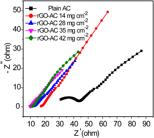
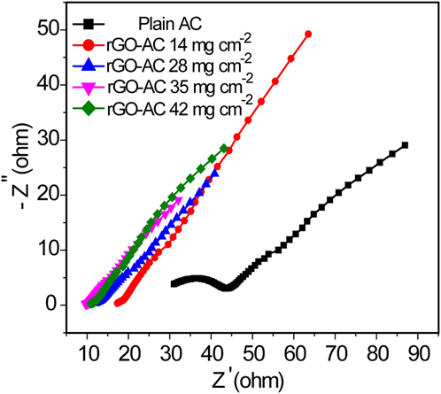
To understand the role of rGO, we compared the cyclic voltammograms (CV) of rGO-AC (35 mg/cm2) and AC. As shown in Fig. S3, rGO-AC exhibits a quasirectangular shape of CV, while the CV of plain AC is highly distorted. The results suggest that rGO-AC has a smaller internal resistance. Nyquist plots were also collected to further determine the resistances of MFCs with different cathodes. All data were collected at a constant external voltage of 0.1 V, and fitted by an equivalent electric circuit shown in Fig. S4. Table I summarizes the EIS fitting results. As shown in Fig. 5, MFCs with rGO-AC cathodes have considerably smaller semicircles in the middle frequency domain compared to the MFC with a plain AC cathode, suggesting these cathodes have smaller charge transfer resistances.Reference Zhang, Pant and Logan17,Reference Zhang, Xia, Ivanov, Huang and Logan26 The rGO-AC (35 mg/cm2) sample exhibited the smallest charge transfer resistance (0.39 Ω) and internal resistance (42.2 Ω), which are orders of magnitude smaller than that of plain AC (charge transfer resistance of 519.38 Ω and internal resistance of 650 Ω). The reduced charge transfer resistance can be attributed to the presence of highly conductive rGO sheets that facilitates charge transfer. Notably, rGO-AC (35 mg/cm2) MFC also has the smallest resistances among the rGO-AC MFCs. The results indicate that 35 mg/cm2 is an optimal AC loading for the rGO-coated Ni foam used in this study. The increased resistance observed for rGO-AC (42 mg/cm2) MFC is believed to be due to the excess AC loading that blocks the pores, as shown in Fig. 2(f).
EIS fitting results of MFCs with different air-cathodes.

Nyquist plots of MFCs with various rGO-AC catalysts under an external voltage of 0.1 V. Frequency range: 10,000–0.01 Hz.
C. Electrochemical performance of rGO-AC cathodes
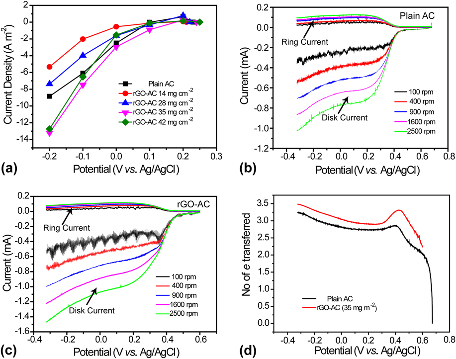
To further investigate the electrochemical properties of different air-cathodes, current–potential curves were collected in a home built electrochemical reactor. As shown in Fig. 6(a), rGO-AC (42 mg/cm2) achieved a current density of 12.7 A/m2 at 0.2 V versus Ag/AgCl, which was substantially higher than that of plain AC (8.8 A/m2) with the same mass loading. The result again confirmed that the electro–catalytic activity of AC was enhanced by mixing with rGO sheets. Furthermore, the exchange current density (j 0) of these cathodes was evaluated by a Tafel test performed in 50 mM PBS (Fig. S5). Exchange current is the current density of working electrode when over-potential is zero. It relates to the electrochemical activity of the electrode at equilibrium state. j 0 was calculated according to the Tafel equation [Eq. (1)] using the data in the linear region (overpotential ranged from 80 to 100 mV, inset of Fig. S5). As shown in Fig. S5, rGO-AC (42 mg/cm2) achieved the maximum j 0 of 2.23 × 10⁻⁴ A/cm2, which was two times higher than that of plain AC (0.93 × 10⁻⁴ A/cm2) with the same mass loading. More importantly, the j 0 of rGO-AC is considerably higher than the values reported for other AC-based cathodes.Reference Dong, Yu and Wang37,Reference Dong, Yu, Wang, Zhou and Feng38 The enhanced current density can be attributed to the increased ORR activity as a result of the well-distributed micro-pores of graphene sheets.
(a) Current–potential curves of plain AC and rGO-AC cathodes collected in 50 mM PBS solution; RRDE voltammograms of catalyst inks of (b) plain AC and (c) rGO-AC 35 mg/cm2 in an oxygen-saturated 0.1 M KOH solution; (d) A plot of number of transferred electrons calculated from the RRDE voltammograms at 1600 rpm.

D. Catalysis kinetics
To understand the catalytic properties of AC and rGO-AC for ORR, RRDE technique was carried out to quantitatively characterize the ORR electron transfer pathway for plain AC and rGO-AC with optimal loading (35 mg/cm2). As shown in Figs. 6(b) and 6(c), the cathodic currents were measured in the potential range between −0.32 V and +0.67 V under different rotating speeds (100, 400, 900, 1600, 2500 rpm). Both catalysts have the same onset potential of +0.35 V versus Ag/AgCl. However, the disk currents generated by rGO-AC at different rotating speeds are considerably larger than the values obtained from plain AC [Fig. 6(c)], indicating improved ORR efficiency on rGO-AC electrode related to number of transferred electrons.Reference Garsany, Baturina, Swider-Lyons and Kocha40,Reference Markovic, Gasteiger and Ross41 Meanwhile, the ring currents were about one order of magnitude smaller than the disk currents under the same potentials. It indicated that peroxide species were rarely generated during the ORR process. Under the low rotating speeds (e.g., 100, 400 rpm), a fluctuation was observed as a result of a relative slow diffusion rate of oxygen to the electrode. To avoid the issue of diffusion-rate limitation, further details in the ORR process were analyzed at high rotating speed approached 900 rpm and beyond. For example, the number of transferred electrons (n) was estimated based on the following equation at 1600 rpm [Eq. (2)]:Reference Lefèvre and Dodelet42
 $$n = {{4{I_{\rm{D}}}} \over {\left( {{I_{\rm{D}}} + {{{I_{\rm{R}}}} \over N}} \right)}}\quad ,$$
where I R is the ring current, I D the disk current, and N the collection efficiency (37%). n increased dramatically from 0 to 3.0 when the potential changed from 0.67 to 0.4 V [Fig. 6(d)]. It is suggested that four-electron water oxidation was the dominant process on AC-species catalysts, in which O2 was mainly converted to OH− rather than HO2−. When potential was further increased, n gradually increased to 3.5 for rGO-AC, which was higher than that of plain AC (n = 3.2). The yield of peroxide was calculated by Eq. (3):Reference Wu, More, Johnston and Zelenay43,Reference Liang, Li, Wang, Zhou, Wang, Regier and Dai44
 $$\% \left( {{\rm{HO}}_2^ - } \right) = 200 \times {{{{{I_{\rm{R}}}} \mathord{\left/ {\vphantom {{{I_{\rm{R}}}} N}} \right. \kern-\nulldelimiterspace} N}} \over {\left( {{I_{\rm{D}}} + {{{I_{\rm{R}}}} \mathord{\left/ {\vphantom {{{I_{\rm{R}}}} N}} \right. \kern-\nulldelimiterspace} N}} \right)}}\quad .$$
The yield of peroxide for rGO-AC catalyst was calculated to be 25.5% at stable catalysis, which was substantially lower than the value of plain AC (38.9%). The results are consistent with the conclusion that the charge transfer efficiency of AC was enhanced by blending it with rGO sheets. The positive role of rGO sheets is believed to be due to its contributions of large specific surface area and abundant micro-/meso-pores, which can increase the number of oxygen reduction areas and facilitate ion transfer.Reference Ren, Zhang, Tran and Read36,Reference Dong, Yu and Wang37 Notably, the ion-accessible surface area of rGO-AC estimated by Trasatti method (Fig. S6)Reference Liu, Finn, Yu, Wang, Zhai, Lu, Tong and Li45,Reference Ardizzone, Fregonara and Trasatti46 is comparable to the value obtained from BET measurements, again proving the unique rGO structure can facilitate electrolyte/ion diffusion.
IV. CONCLUSIONS
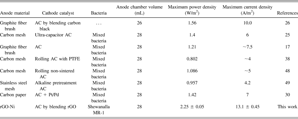
In summary, we have successfully synthesized a new ORR catalyst for MFC cathode by mixing AC with rGO sheets. Table II summarizes the performance of some recently reported MFCs with AC-based air-cathodes and compares to the MFC performance with rGO-AC as catalysts. MFC with rGO-AC (35 mg/cm2) produces a maximum power density of 2.25 ± 0.05 W/m2, which is the highest value obtained from air-cathode MFCs inoculated with pure strain of S. oneidensis MR-1 in a similar size reactor. The new rGO-AC catalyst in terms of cost (∼$2 per gramReference Xie, Yu, Liu, Bao, Criddle and Cui47) should be potentially affordable for large scale MFC systems.
Comparison of MFC device performance of using different AC air-cathodes.

Supplementary Material
To view supplementary material for this article, please visit https://doi.org/10.1557/jmr.2017.283.
ACKNOWLEDGMENTS
This work is supported by the National Natural Science Funds for Distinguished Young Scholar (No. 51325602), International Cooperation and Exchange of the National Natural Science Foundation of China (No. 51620105011), National Natural Science Foundation of China (No. 51376203). Y.L. thanks the financial support from NSF (IIP-1550327). Y.Y. thanks the China Scholarship Council for financial support and the Fundamental Research Funds for the Central Universities (3102017OQD011).