Introduction
Substrate integrated waveguide (SIW) has attached much attention due to its merits of low loss, low cost, low interference, easy fabrication, and planar integration [Reference Bozzi, Georgiadis and Wu1]. However, the footprint of the SIW is large. For size reduction, several SIW-derived transmission lines (TLs), including the half-mode SIW (HMSIW) [Reference Lai, Fumeaux, Hong and Vahldieck2], ridge SIW [Reference Bozzi, Winkler and Wu3], and folded SIW (FSIW) [Reference Grigoropoulos, Sanz-Izquierdo and Young4, Reference Che, Geng, Deng and Chow5], have also been proposed. Based on these structures, a variety of microwave devices, such as bandpass filters [Reference Macchiarella, Tomassoni and Bozzi6–Reference Zhu, Luo, You, Zhang and Wu8], directional couplers [Reference Ho, Hong and Li9, Reference Bayati and Khorand10], and phase shifters [Reference Cheng, Yao, Tomura, Hirokawa, Yu, Yu and Chen11–Reference Liu and Xu18], have been proposed. To feature as a good phase shifter, it has to show a wide bandwidth, a good impedance matching, a low insertion loss, a compact size, and an equal-length structure.
Traditional SIW phase shifters implemented by delay lines [Reference Xu, Bosisio and Wu12] or equal-length unequal-width SIWs [Reference Cheng, Hong and Wu13] are frequency dependent, and therefore, they are narrowband in nature. In [Reference Cheng, Hong and Wu14], a wideband (49%) self-compensating SIW phase shifter is proposed. However, this phase shifter and its reference line show different physical lengths. To achieve a wide bandwidth with an equal-length structure, a dielectric slab [Reference Cano, Villa, Mediavilla and Artal15] or an artificial dielectric slab [Reference Djerafi, Wu and Tatu16, Reference Boudreau, Wu and Deslandes17] can be inserted into the SIW. However, a multi-section impedance transformer is required for a wideband impedance matching, resulting in a large circuit size. By etching complementary split-ring resonators (CSRRs) on the cover of SIW or HMSIW, more compact equal-length phase shifters with a wide bandwidth are realized [Reference Liu and Xu18]. However, they suffer from a high insertion loss and a large amplitude imbalance caused by the radiation loss of the CSRRs. Therefore, each of the existed SIW phase shifters accomplishes only part of the requirements.
On the other hand, a 180° directional coupler is a key component in many microwave circuits, such as push-pull amplifiers, balanced mixers, and antenna feeding networks. To provide a 180° coupler characteristic, several hybrid ring couplers based on SIW and FSIW techniques have been proposed [Reference Che, Deng, Yung and Wu19, Reference Ding and Wu20]. However, these structures suffer from a large footprint. Another technique of cascading a 90° directional coupler with a 90° phase shifter to obtain a 180° directional coupler has also been proposed in [Reference Liu, Hong, Zhang, Tang, Yin and Wu21–Reference Li and Luk23]. However, the bandwidth of the 180° directional coupler is limited by the phase shifter.
In this paper, a broadband equal-length CSRR-loaded FSIW phase shifter is proposed for the first time. By loading the CSRRs on the middle metal layer of the FSIW, a closed-type slow-wave TL is obtained, which can provide a wideband phase shift (39%) compared with the equal-length fast-wave one. The enclosed structure of the CSRR-loaded FSIW prevents the CSRRs from radiation as suffered in the CSRR-loaded SIW and HMSIW TLs [Reference Liu and Xu18], resulting in a low insertion loss. This feature greatly reduces the amplitude imbalance between the main line and the reference line of the phase shifter. Thus, the proposed design exhibits a lower insertion loss and a smaller amplitude imbalance as compared with the CSRR-loaded SIW and HMSIW phase shifters in [Reference Liu and Xu18]. Furthermore, an FSIW 180° directional coupler that consists of an FSIW 90° coupler and a 90° phase shifter is designed, fabricated, and measured to verify the concept. The proposed FSIW 180° directional coupler exhibits a wide bandwidth while occupies a small circuit size.
FSIW phase shifter
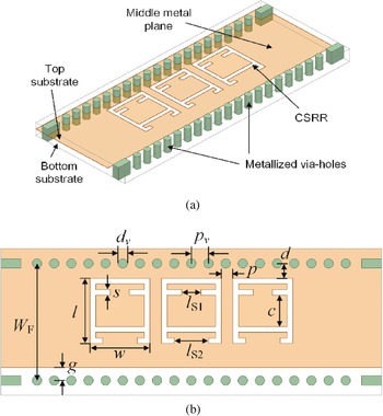
Figure 1 shows the structure of the proposed CSRR-loaded FSIW. It consists of two layers of dielectric substrate, two rows of metallic via-holes, and three metal planes. Both of the substrates are Tanconic TLY-5 with relative dielectric constant ɛr = 2.2, loss tangent tanδ = 0.0009, and thickness h = 0.508 mm. The metallic via-holes are connected between the top and bottom metal planes, which are not shown here for better charity of the interior details. The diameter of the metallic via-holes is dv = 0.5 mm, and the space between two adjacent via-holes is pv = 0.9 mm. The CSRRs are etched on the middle metal plane of the FSIW with a periodical arrangement to implement a slow-wave TL with a closed structure.
Configuration of the CSRR-loaded FSIW phase shifter. (a) 3D view. (b) Top view.

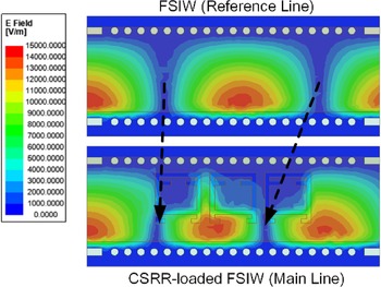
To illustrate the slow-wave effect of the CSRR-loaded FSIW, full wave simulations of the proposed structure were carried out by using Ansys high-frequency structure simulator. Figure 2 shows the simulated electric field distributions inside the normal FSIW and the CSRR-loaded FSIW at 13 GHz. For the CSRR-loaded FSIW, typical folded TE10 mode is firstly excited, when it transmits to the CSRR-loaded region, the guided wavelength is reduced, revealing that the phase velocity is slowed down. Therefore, a stable phase shift can be obtained between the equal-length FSIWs with and without CSRRs.
The E-field distributions inside the normal FSIW and the CSRR-loaded FSIW at 13 GHz.

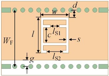
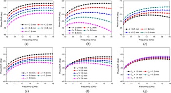
To know in detail how the parameters affect the phase shift performance, a CSRR-loaded FSIW unit cell, as shown in Fig. 3, is studied. To begin with, the parameters are set as follows: w = l = 3, s = 0.3, c = 1.6, d = 0.6, lS 1 = lS 2 = 1.6, WF = 6.3, and g = 0.7 (unit: mm). Figure 4 shows the simulated phase shifts of the unit cell against different values of w, l, s, c, d, and lS 2. As can be observed, the phase shift of a unit cell can be varied from 20° to 40° in 10–16 GHz. It increases with the increase of the values of w, l, and d, and decreases with the increase of the values of s, c, and lS 2. In addition, the slope of the phase shift can be controlled by modifying the values of l, s, and d. In this way, a flat phase shift over a wide bandwidth can be obtained. The parameter lS 1 has little influence on the phase shift. It should be mentioned that, in Figs 4(a)–4(g), only one parameter is swept at the same time, while the other parameters are kept unchanged. If two or more parameters (e.g. w and l) are adjusted simultaneously, the phase shift range of the unit cell would be larger than 20–40 degree. Due to the strong loading effect of the CSRR, only countable CSRR-loaded cells are needed to obtain a required phase shift, resulting in a compact size.
Layout of the CSRR-loaded FSIW unit cell.

Simulated phase shifts of a CSRR-loaded unit cell against different values of (a) w, (b) l, (c) s, (d) c, (e) d, and (f) lS 2.

To realize a 90° phase shifter, three CSRRs are needed. Figure 5(a) shows the simulated phase shift of the 90° phase shifter, whose dimensions are: w = 3.15, l = 3.5, s = 0.3, c = 1.7, d = 0.8, lS 1 = 1, lS 2 = 1.8, p = 0.6, WF = 6.3, and g = 0.7 (unit: mm). As can be observed, a stable phase shift of 90° ± 5° is obtained from 10.6 to 16.3 GHz. Figure 5(b) shows the simulated |S 21| and |S 11| of the CSRR-loaded FSIW (i.e. the main line) and the simulated |S 21| of the normal FSIW (i.e. the reference line). From 10.6 to 15.7 GHz, the insertion losses of both the main line and the reference line are lower than 0.2 dB, and the amplitude imbalance between them is less than 0.1 dB. The simulated return loss (|S 11|) of the CSRR-loaded FSIW is better than 20 dB from 10.6 to 15.7 GHz without using any transition structures. This makes the proposed phase shifter more compact and easier to integrate with other devices. The core size of the FSIW 90° phase shifter is 10.65 mm × 6.3 mm, excluding the input and output FSIW sections.
Simulated results of the 90° phase shifter. (a) Phase shift. (b) S-parameters.

Table 1 summarized a comparison between the proposed FSIW phase shifter and other existing SIW and HMSIW phase shifters. Compared with the phase shifters in [Reference Cheng, Hong and Wu14–Reference Djerafi, Wu and Tatu16], the proposed design achieves a more compact size. Compared with the CSRR-loaded SIW and HMSIW phase shifters [Reference Liu and Xu18], the proposed design exhibits a lower insertion loss and a smaller amplitude imbalance, thanks to the closed structure. It should be mentioned that the size reduction of the proposed phase shifter is not only contributed by the folded structure, but also contributed by the slow-wave effect and the non-transition structure. Therefore, the size of the proposed FSIW phase shifter is smaller than 50% of the SIW counterparts.
Comparison with other broadband phase shifters

f 0, center frequency; AI, amplitude imbalance; EL, equal length for reference and main lines; λg, wavelength in the dielectric substrate at f 0.
FSIW 180° directional coupler
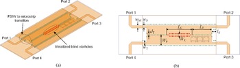
To validate the performance of the proposed phase shifter and to illustrate its ease integration, an FSIW 180° directional coupler that consists of an FSIW 90° coupler [Reference Sun, Ban, Lian, Liu and Nie24] and an FSIW 90° phase shifter is designed, fabricated, and measured. The structure of the 180° directional coupler is shown in Fig. 6, and the detailed dimensions are WF = 6.3, LF = 11.65, WC = 1.4, LC = 15.2, dT = 0.85, lS = 2.6, wT = 2.95, wS = 1.2, wM = 1.55, g = 0.7, w = 3.3, l = 3.4, s = 0.2, lS 1 = 1.3, lS 2 = 2, p = 0.5, c = 1.8, d = 0.8 (unit: mm).
Configuration of the FSIW 180° coupler. (a) 3D view. (b) Top view.

By adjusting the length LC of the coupling region and the distance WC of the two rows of metallized blind via-holes (red ones) on the bottom substrate, a flat 90° phase difference with a stable power ratio can be obtained [Reference Sun, Ban, Lian, Liu and Nie24]. The CSRR-loaded phase shifter is used to provide another 90° phase shift. A broadband microstrip to FSIW transition [Reference Xu, Xu and Li25] is used for measurement.
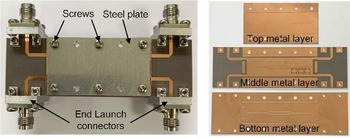
The photograph of the fabricated FSIW 180° coupler is shown in Fig. 7. The PCB processing technology is used for layered processing. Considering the integration of the whole structure, two steel plates are added to the upper and lower surfaces of the coupler, and the double layers are manually tightened with screws. The core size of the proposed 180° coupler is 26.85 mm × 12.6 mm, where the length is calculated by adding the length of the coupling region (LC) and the length of the phase shifter (LF). The fabricated 180° coupler is measured by using a Keysight N5234B vector network analyzer, two ports at a time, with the unused ports terminated in a 50 Ω loads.
Photograph of the fabricated FSIW 180° coupler.

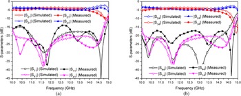
Figure 8 shows the simulated and measured S-parameters of the FSIW 180° coupler. When the coupler is excited at port 1, the measured |S 11| is better than 13.8 dB from 10 to 14.8 GHz, and the measured |S 21| and |S 31| are −4.5 ± 0.5 dB in 10.5–13.9 GHz with a fractional bandwidth (FBW) of 28%. When the coupler is excited at port 4, the measured |S 44| is better than 17 dB from 10 to 14.8 GHz, and the measured |S 24| and |S 34| are −4.6 ± 0.5 dB in 10.5–13.6 GHz with an FBW of 26%. The measured isolation between port 1 and port 4 is better than 19.5 dB from 10.1 to 14.6 GHz. Considering the insertion losses of the End Launch connectors, the measured results are in accordance with the simulated data.
Simulated and measured S-parameters of the proposed 180° coupler. (a) Excited at port 1. (b) Excited at port 4.

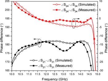
Figure 9 shows the simulated and measured phase difference between port 2 and port 3 under different scenarios. The measured phase difference is 180° ± 5° from 10.3 to 14.4 GHz for an excitation of port 1 and 0° ± 5° from 10.5 to 14.7 GHz for an excitation of port 4, which are consistent with the simulated ones.
Simulated and measured phase difference between port 2 and port 3 of the proposed 180° coupler.

Table 2 summarized a comparison between the proposed 180° directional coupler and other 180° directional couplers. The proposed 180° directional coupler exhibits the widest bandwidth while occupies the smallest circuit size.
Comparison with other 180° couplers

*The length of the coupler is calculated by adding the length of the coupling region and the length of the phase shifter; f 0, center frequency; λg, wavelength in the dielectric substrate at f 0; AI, amplitude imbalance; PI, phase imbalance.
Conclusion
In this paper, a CSRR-loaded FSIW phase shifter and its application to a 180° directional coupler is presented. By loading the CSRRs on the middle metal layer of the FSIW, a broadband (39%), low insertion loss (<0.2 dB), and compact equal-length phase shifter is obtained. Compared with the SIW and HMSIW counterparts, the proposed phase shifter exhibits a lower insertion loss and a lower amplitude imbalance. To validate the concept, an FSIW 180° directional coupler that consists of an FSIW 90° coupler and an FSIW 90° phase shifter is designed, fabricated, and measured. Good agreement between the simulated and measured results is obtained.
Acknowledgement
This work was supported in part by the “Pioneer” and “Leading Goose” R&D Program of Zhejiang under Grant 2022C01119 and in part by the Natural Science Foundation of China under Grant 61901147 and 62125105.
 Fang Zhu received the B.S. degree in electronics and information engineering from Hangzhou Dianzi University, Hangzhou, China, in 2009, and the M.S. and Ph.D. degrees in electromagnetic field and microwave technique from Southeast University, Nanjing, China, in 2011 and 2014, respectively. From 2014 to 2016, he was a MMIC Designer with Nanjing Milliway Microelectronics Technology Co., Ltd, Nanjing, China. From 2016 to 2019, he was a Postdoctoral Research Fellow with the Poly-Grames Research Center, Polytechnique Montréal, Montréal, QC, Canada. He is currently a Professor with the School of Electronics and Information, Hangzhou Dianzi University, Hangzhou, China. His current research interests include microwave and millimeter-wave integrated circuits, components, and transceivers for wireless communication and sensing systems.
 Xin Zhao received the B.S. degree from the Nanjing University of Posts and Telecommunications, Nanjing, China, in 2017. He is currently pursuing the M.S. degree with Hangzhou Dianzi University, Hangzhou, China. His current research interests include microwave and millimeter-wave integrated circuits and high-performance passive components.
 Junhao Sheng received the B.S. degree in electronic science and technology from Hunan City University, Yiyang, China in 2019. He is currently pursuing the M.S. degree with Hangzhou Dianzi University, Hangzhou, China. His current research interests include microwave and millimeter-wave integrated circuits and high-performance passive components.
 Guo Qing Luo received the B.S. degree from the China University of Geosciences, Wuhan, China, in 2000, the M.S. degree from Northwest Polytechnical University, Xi'an, China, in 2003, and the Ph.D. degree from Southeast University, Nanjing, China, in 2007. Since 2007, he has been a Lecturer with the Faculty of School of Electronics and Information, Hangzhou Dianzi University, Hangzhou, China, and was promoted to Professor in 2011. From October 2013 to October 2014, he joined the Department of Electrical, Electronic and Computer Engineering, Heriot-Watt University, Edinburgh, UK, as a Research Associate, where he was involved in developing low-profile antennas for UAV applications. He has authored or co-authored over 110 technical papers in refereed journals and conferences and holds 19 patents. His current research interests include RF, microwave and mm-wave passive devices, antennas, and frequency-selective surfaces.