I. INTRODUCTION
The subject of peritectic reaction and solidification in recent years has attracted many investigators to research the physical process, which frequently occurs in many important alloys, such as structural alloys (Fe–C, Cu–Sn, Ti–Al, and Al–Fe–Si), YBa2Cu3Oy high temperature superconductors, and Nd–Fe–B rare-earth permanent magnetic materials. Reference Kerr and Kurz1–Reference Choudhury, Nestler, Telang, Selzer and Wendler6 The morphologies and volume fractions of the primary and peritectic phases after peritectic solidification will influence the mechanical and physical properties of the materials directly.
Pioneering contributions on the peritectic reaction process were made earlier by Hillert,
Reference Hillert2
who predicted the morphology of the triple phase region. Boussinot and Stjohn et al. systematically studied the mechanism of peritectic reaction and transformation.
Reference Choudhury, Nestler, Telang, Selzer and Wendler6–Reference Stjohn9
Kerr and Kurz
Reference Kerr and Kurz1
reviewed various peritectic systems comprehensively. Sha et al.
Reference Sha, O’Reilly, Cantor, Titchmarsha and Hamerton10
proposed a more detailed theory on the peritectic reaction process in Al–Si–Fe alloy. During peritectic solidification, two stages have been identified in terms of growth of the peritectic phase
Reference Kerr and Kurz1
: the first stage is the “peritectic reaction,” which occurs at the temperature of peritectic reaction
 $\left( {T_{\rm{p}}^K} \right)$
and is controlled by solute diffusion in the liquid phase at the three phase junction; the second stage is the “peritectic transformation,” which occurs below
 $T_{\rm{p}}^K$
and is controlled by solute diffusion in the secondary phase. It is generally believed that, during peritectic transformation, the primary phase is completely enveloped by the peritectic phase. Thus, the remelting of the primary phase will only occur at
 $T_{\rm{p}}^K$
during peritectic reaction.
Reference Fredriksson and Nylén8,Reference Sha, O’Reilly, Cantor, Titchmarsha and Hamerton10–Reference Phelan, Reid and Dippenaar13
However, in this paper, different from traditional understanding, a lateral remelting phenomenon of the primary phase below
 $T_{\rm{p}}^K$
is observed in directionally solidified Cu–Ge alloys. In the peritectic system, lateral remelting is a novel nature phenomenon and is found for the first time, as far as we know. The lateral remelting phenomenon accompanies new features and has new formation mechanism. The phenomenon also means that classical theory calculating the volume fraction (or predicting the morphology) of the primary phase during peritectic transformation needs to be modified under high velocities. A model is set up to explain the lateral remelting phenomenon.
II. EXPERIMENTAL PROCEDURE
In this study, Cu–Ge alloys, a typical peritectic alloy, have recently attracted much attention. According to the phase diagram, Reference Zhai, Geng, Wang and Wei14 the peritectic reaction, α(13.48 wt% Ge) + L(19.5 wt% Ge) → ζ(14.4 wt% Ge) occurs at 824 °C. The freezing range of the primary α and peritectic ζ phases (about 120 and 80 K, respectively) is very big such that the dendritic α and nonplanar ζ in this system can be easily obtained during peritectic solidification.
High-purity copper (99.99%) and germanium (99.99%) were melted by electromagnetic induction heating under high pure argon atmosphere in a graphite crucible. The samples were machined to 3.8 mm in diameter and kept in an alumina tube with 4-mm inner diameter. Then the sample was solidified in a Bridgman furnace, which is consisted of two heaters: primary heater I and secondary heater II (W tubes heated by resistance heating). After heated to stabilization at 1250 °C, the sample was pulled downward at a constant velocity. At the end of the experiment, the directionally solidified samples were quenched in liquid metal (Ga–In–Sn) cooling bath. Electrolytic deep etching technique was applied to differentiate the quenched solid/liquid boundaries, which was performed at 293 K for 60 s in a solution consisting of 30% H2O and 70% H3PO4 (by volume). The microstructures were examined by using a combination of Olympus optical microscope (GX-71, Miyazaki-ken, Kyushu area, Japan) and scanning electron microscope (Quanta 200FEG, Hillsboro, OR).
III. RESULTS AND DISCUSSION
A. Microstructure
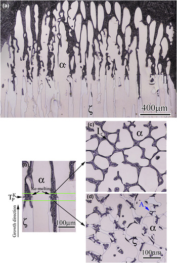
Figure 1 shows the longitudinal and transversal microstructures of the sample for Cu–6.5 wt% Ge alloys which were directionally solidified at G = 25 K/mm and V = 3 μm/s. At
 $T_{\rm{p}}^K$
, the longitudinal remelting along the growth direction occurs near the liquid/α/ζ trijunctions during peritectic reaction, and the diameters of the α cells decrease behind the trijunctions [Fig. 1(b)]. In the images that are above and below 30 μm from the interface of peritectic reaction, the boundaries of the α cells are smoother [Figs. 1(c) and 1(d)].
Microstructures of the mushy zone near triple junction in a directionally solidified Cu–16.5 wt% Ge alloy growth at V = 3 μm/s and G = 25 K/mm: (a) longitudinal section; (b) regions of peritectic reaction; (c) and (d) transverse sections above and below 30 μm from the interface of peritectic reaction, respectively.

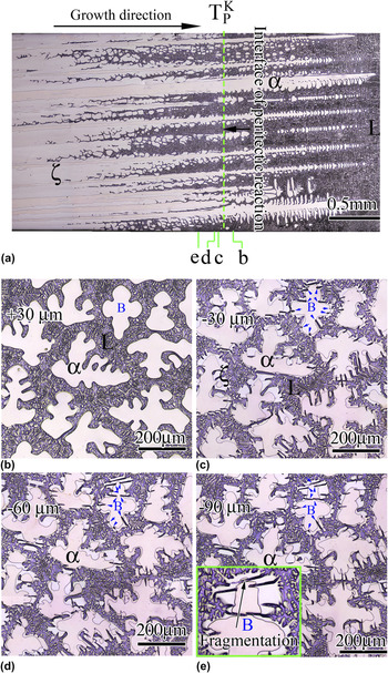
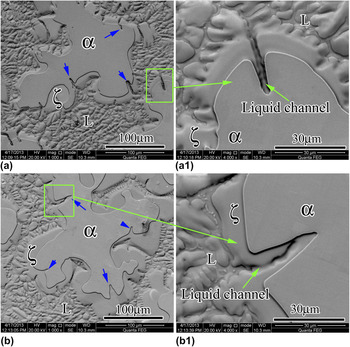
As the velocity increases to V = 10 μm/s, a mixed structure is observed consisting of dendritic α and nonplanar ζ, as shown in Fig. 2(a). Figures 2(b)–2(e) present a series of the dendrites at different transversal sections in the mushy zone. In the image that is above 30 μm from the interface of peritectic reaction, the boundaries of the α dendrites are very smooth [Fig. 2(b)]. However, in the transversal section [Fig. 2(c)], that is below 30 μm from the interface of peritectic reaction, some grooves are found in the boundaries of the α dendrites. For example, in the α dendrite marked “B” [see Fig. 2(c)], about 10 grooves form around the dendrite boundary, which are pointed by blue arrows. As solidification proceeds, the depth of the grooves increases [e.g., the dendrite “B,” Figs. 2(c)–2(e)]. The morphologies of the groove regions are shown in Figs. 3(a) and 3(a1). In Fig. 3(a1), the α groove directly contacts with the liquid phase though a liquid channel, which consists of the two sides of ζ and the remelting groove of α. The results suggest that the lateral remelting phenomenon of α is controlled by the liquid state diffusion through the liquid channel. The lateral remelting makes the structure of the α dendrites more complex, even leads to the fragmentation of some dendrite branches [see the inset in Fig. 2(e)].
Microstructures of directionally solidified Cu–16.5 wt% Ge alloy growth at V = 10 μm/s and G = 25 K/mm. (a) Longitudinal section, (b–e) transversal sections of the mushy zone at varying distances from the interface of peritectic reaction: (b) above 30 μm [+30 μm]; (c) below 30 μm [−30 μm]; (d) below 60 μm [−60 μm]; and (e) below 90 μm [−90 μm].

Transversal SEM microstructures of the directionally solidified Cu–16.5 wt% Ge alloy at V = 10 μm/s and G = 25 K/mm. (a) The lateral remelting of α is happening through a liquid channel, (b) the remelting region is completely encased by ζ. (a1) and (b1) are enlarged views of the remelting region, which are labeled in (a) and (b), respectively.

In Figs. 2(c)–2(e), as the volume fraction increases in the peritectic ζ phase, some grooves are completely covered by the peritectic ζ phase. Figures 3(b) and 3(b1) show the microstructures of the covered grooves. In Fig. 3(b1), the liquid channel is isolated. Then, the dissolution of the α phase only depends on the solid-state diffusion through the ζ phase (peritectic transformation: L → ζ → α). Actually, the lateral remelting also forms in Fig. 1(d) [see the dendrite “A”]. However, it is not so significant.
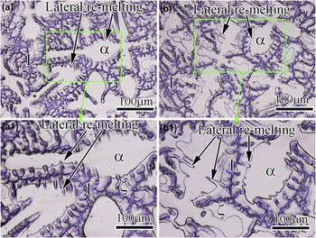
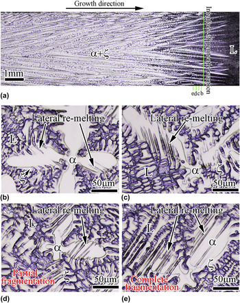
As the velocity increases to 150 μm/s, the lateral remelting of the primary α phase is obtained again, as shown in Figs. 4(a) and 4(a1). However, the depth of the lateral remelting does not increase significantly after the primary phase is completely enveloped, as shown in Figs. 4(b) and 4(b1). The segregation in the α dendrite can affect the lateral remelting velocity. As shown in Fig. 5, when the velocity is 150 μm/s and the alloy composition increases to 18.0 wt% Ge, the lateral remelting runs through the whole dendrites of α. In the image that is below 10 μm from the interface of peritectic reaction, the lateral remelting is observed [Fig. 5(b)]. As solidification proceeds, the depth of the grooves obviously increases [Figs. 5(c) and 5(d)]. In the transversal section [Fig. 5(d)] that is below 30 μm from the interface of peritectic reaction, the α dendrite partly fragments. In the transversal section [Fig. 5(e)] that is below 50 μm from the interface of peritectic reaction, the α dendrite completely fragments and the single dendrite is split into dozens of small parts.
Microstructures of directionally solidified Cu–16.5 wt% Ge alloy growth at V = 150 μm/s and G = 25 K/mm. Transversal sections of the mushy zone at varying distances from the interface of peritectic reaction: (a) below 20 μm and (b) below 60 μm. (a1) and (b1) are enlarged views of the remelting region, which are labeled in (a) and (b), respectively.

Microstructures of directionally solidified Cu–18.0 wt% Ge alloy growth at V = 150 μm/s and G = 25 K/mm. (a) Longitudinal section, (b–e) transversal sections of the mushy zone at varying distances from the interface of peritectic reaction: (b) below about 10 μm; (c) below 20 μm; (d) below 30 μm; and (e) below 50 μm.

The lateral remelting velocity of α is faster than that of peritectic transformation, which proceeds by the solid diffusion. Compared to peritectic transformation, the decrease of the α phase caused by the lateral remelting is considerable. The phenomenon means that classical methods calculating the volume fraction of the primary phase during peritectic transformation can need to be modified.
B. Morphologies of the peritectic phase during peritectic reaction
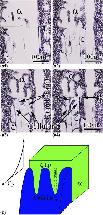
Although the longitudinal and transversal morphologies of α and ζ are observed in Fig. 2, the three-dimensional morphology of ζ connecting the α/ζ interface and the longitudinal structure of the liquid channel are not fully presented. Figures 6(a2)–6(a4) show the various longitudinal sections of one α dendrite that is about 5, 10, 15 μm under the section of Fig. 6(a1), respectively. The observation of successive layers shows that the ζ phase presents cellular morphology along the α/ζ boundary and some liquid channels form between the neighboring ζ cells [see Fig. 6(b)]. Similar to free solidification, during the spreading of ζ along the L/α interface, the ζ–liquid tip can grow in cellular/dendritic morphology due to the constitutional undercooling and surface tension effects.
Reference Kohler, Germond, Wagnière and Rappaz15
The constitutional undercooling degree can be estimated by the difference between the temperature gradient and the gradient of the liquidus. At
 $T_{\rm{p}}^K$
, the peritectic phase with the concentration close to
 $C_{\rm{p}}^{\rm{\zeta }}$
starts to grow from melt because peritectic reaction occurs, where
 $C_{\rm{p}}^{\rm{\zeta }}$
is the equilibrium concentration of ζ at T
P [Figs. 7(a) and 7(b)]. The use of Fick's first law of diffusion and the application of a mass balance at the solidifying ζ tip result in the following differential equation:
 $${\left. { - {D_{\rm{L}}}{{\partial {C_{\rm{L}}}} \over {\partial x}}} \right|_{x = 0}} = - {D_{\rm{L}}}{G_{\rm{c}}} \approx {{VC_{\rm{p}}^{\rm{\zeta }}(k - 1)} \over k}\quad ,$$
where G
c is the concentration gradient at the solidifying ζ tip, D
L is the solute diffusion coefficient in the liquid, and
 $k$
is the partition coefficient. According to Eq. (1), the liquidus gradient (
 $m_{\rm{L}}^{\rm{\zeta }}{G_{\rm{c}}}$
) at the solidifying ζ tip can be expressed as
 $$m_{\rm{L}}^{\rm{\zeta }}{G_{\rm{c}}} = {{m_{\rm{L}}^{\rm{\zeta }}VC_{\rm{P}}^{\rm{\zeta }}(1 - k)} \over {k{D_{\rm{L}}}}}\quad ,$$
where
 $m_{\rm{L}}^{\rm{\zeta }}$
is the liquidus slope of ζ. When V = 10 μm/s, taking k = 0.74 and
 $m_{\rm{L}}^{\rm{\zeta }}$
≈ 12.5 K/wt% Ge (determined by phase diagram
Reference Zhai, Geng, Wang and Wei14
) and D
L ≈ 5 × 10⁻⁹ m2/s,
Reference Wang, Luo, Su, Dong, Guo and Fu16
G (25 K/mm) is significantly smaller than the value of
 $m_{\rm{L}}^{\rm{\zeta }}{G_{\rm{c}}}$
(=
 $m_{\rm{L}}^{\rm{\zeta }}VC_{\rm{P}}^{\rm{\zeta }}(1 - k)/(k{D_{\rm{L}}})$
≈ 126 K/mm). In addition, at
 $T_{\rm{p}}^K$
, the longitudinal remelting of α caused by peritectic reaction dilutes the Ge concentration ahead of the ζ tip, which also increases the concentration gradient ahead of the ζ tip. Thus, the constitutional undercooling at the ζ tip can be a key factor to induce the morphological instability of the ζ tip. Figure 7(b) shows the morphologies of the ζ tip and the liquid channel.
(a1–a4) Various longitudinal sections of one α dendrite (V = 10 μm/s and G = 25 K/mm). (a2), (a3), and (a4) are the sections that are about 5, 10, 15 μm under the section of (a1), respectively. (b) The growth of the ζ-phase can be unstable, thus leading to the formation of cells.

Schematic illustration of the lateral remelting of the α phase below
 $T_{\rm{p}}^K$
: (a) peritectic phase diagram; (b) longitudinal section map; (c) A–A1 transversal section map of (b); and (d) lateral remelting process of α.

However, when
 $m_{\rm{L}}^{\rm{\zeta }}{G_{\rm{c}}}$
< G, the ζ phase can grow with planar solidification front. Then the lateral remelting will not occur because the α phase is completely enveloped by the ζ phase. In the steady-state growth region of ζ, only the longitudinal remelting of the α phase occurs near the trijunction during peritectic reaction.
C. Formation of the lateral remelting phenomenon
The intercellular liquid (below
 $T_{\rm{p}}^K$
) between two adjacent ζ cells provides a diffusion channel of the solute (Ge) for lateral remelting. For example, at T
L (below
 $T_{\rm{p}}^K$
), the intercellular liquid contacts with the interface of the ζ phase, which is rich in solute Ge at
 $C_{\rm{L}}^{\rm{\zeta }}$
[see Figs. 7(a) and 7(b)]. However, the concentration of the liquid in equilibrium with α phase is
 $C_{\rm{L}}^{\rm{\alpha }}$
.
 $C_{\rm{L}}^{\rm{\zeta }}$
is higher than
 $C_{\rm{L}}^{\rm{\alpha }}$
, as shown in Fig. 7(a). Thus, the liquid in the channel is supersaturated with respect to the α phase, which will lead to the remelting of the α phase along the α/L boundary [Figs. 7(a) and 7(d)]. The remelting α phase will supply Cu atoms to the liquid in the channels. Then, liquid diffusion of Ge atoms toward the remelting groove of the α phase and Cu toward the interface of the ζ phase occurs in the liquid channel [Fig. 7(d)]. The concentration difference between
 $C_{\rm{L}}^{\rm{\zeta }}$
and
 $C_{\rm{L}}^{\rm{\alpha }}$
,
 $\Delta C_{\rm{L}}^{{\rm{\zeta }} - {\rm{\alpha }}}$
is the driving force of the lateral remelting. As the temperature decreases,
 $\Delta C_{\rm{L}}^{{\rm{\zeta }} - {\rm{\alpha }}}$
increases according to the phase diagram in Fig. 7(a), which will enhance the lateral remelting velocity. At the same time, the liquid channel narrows and its length increases because of the growth of ζ. Then, the solute (Ge) transport becomes more difficult, and thus, the size of the remelting region gradually becomes smaller. Finally, the liquid channel will be completely covered by neighboring ζ because of the lack of the solute (Ge), and then the lateral remelting is terminated.
The above analysis mainly discusses the ideal situation of the lateral remelting. In fact, due to segregation in the α dendrites, the actual concentration of α in the center of the dendrites is lower than the equilibrium concentration of α at T
L
. Thus, solid diffusion will also occur at the remelting interface to increase the concentration of α. In general, the solid solute diffusion coefficient at the melting point ranges from 10−14 to 10−12 m2/s, which is far less than the liquid solute diffusion coefficient (about 5 × 10⁻⁹ m2/s). Thus, the segregation in the α dendrite will significantly lower the lateral remelting velocity of α. However, in Fig. 5, the alloy composition (18.0 wt% Ge) is nearly up to the liquid equilibrium concentration of peritectic reaction (
 $C_{\rm{p}}^{\rm{L}}$
= 19.5 wt% Ge). The concentration of the α dendrite is more uniform and is close to the equilibrium concentration of α at T
L. Thus, the lateral remelting velocity in Fig. 5 is higher than that in Fig. 4. In addition, because the solid composition of the secondary dendrite arms is higher than that of the dendrite trunks, the remelting is easy to take place in the dendrite arms.
IV. CONCLUSIONS
In summary, a lateral remelting phenomenon of the primary phase below the peritectic temperature is reported under high pulling velocity, which is an important supplement to peritectic reaction and transformation theory. During the growth of ζ around the boundary of one α dendrite, the constitutional undercooling at the ζ tip induces that the ζ phase presents cellular morphology. The lateral remelting phenomenon is caused by the solute enrichment between two neighboring ζ cells. When the alloy composition comes closer to
 $C_{\rm{p}}^{\rm{L}}$
, the lateral remelting under high pulling velocity even leads to the fragmentation of dendrites, which may be a candidate method to refine the microstructure of the alloy.
ACKNOWLEDGMENTS
This research was supported by the National Science Foundation of China (Grant Nos. 50901025 and 50975060), National Basic Research Program of China (Grant No. 2011CB610406), “Fundamental Research Funds for the Center Universities” (Grant No. HIT.BRET1.20100008), and Natural Science Foundation of Hei Longjiang Province (Grant No. JC201209).