Introduction
The glacier surface is constantly changing due to glacier flow, snow accumulation and ablation. The shape of an ice mass and its evolution in time is important because it can be a measure of the mass-balance changes and the initial boundary conditions of ice-sheet models.
In Svalbard, mass-balance measurements have been carried out on two small glaciers (≈5 km2) in northwest Spitsbergen for nearly 30 years. On other glaciers mass-balance investigations have been conducted for shorter periods of about 5 years. However, all measurements have been carried out on small valley or cirque glaciers, about 5 km2, close to the west coast. These glaciers show a stable negative net balance over the whole period. Investigations on Kongsvegen (105 km2) since 1987 indicate that larger glaciers and ice fields with a large part of the accumulation area at higher altitudes than the small valley glaciers are closer to a zero net balance (Hagen, 1996).
Direct measurements of the annual mass-balance components, by means of snow soundings and ablation stakes, are, however time-consuming and can only be carried out on some selected reference glaciers. The measurement of a change in surface elevation indicates a volume change, assuming that the density of the glacier does not change. Changes in glacier mass can then be calculated and thereby mean yearly net mass balance over the period between surveys. Measurement of the changes in geometry will also give information about elevation changes at different altitudes, and thus an indication of whether or not the glacier is building up towards a surge.
The objective of this paper is to see if a precise global positioning system (GPS) survey of surface elevation changes, using both point measurements (static GPS) and continuous altitude profiles (kinematic GPS), can be used to detect and monitor mass-balancc/geometry changes of glaciers. This requires a test and discussion on the accuracy of and comparison between static and kinematic surveying. In addition, we will show some results from Kongsvegen where profiles measured in 1992 were remeasured in 1996.
GPS: Some Basic Concepts
GPS, or more precisely NAVSTAR-GPS, is a U.S. military system developed to provide accurate navigation for any military purpose. The basic principle of GPS is the fixing of positions by measuring the distances from a receiver to four or more satellites whose position at the time can be calculated from known parameters. The use of a single receiver will give an accuracy of only tens of metres. If two or more receivers are tracking the same GPS signals, the relative co-ordinates between the receivers can be determined by post-processing collected data, or real-time data links.
The differential processing can be based on “code” measurements with accuracy at the metre to sub-metre level (Ørpen, 1992), or differential carrier-phase measurements, where an accuracy of centimetres can be obtained (Ayers and Yan, 1995). The method depends on equipment, and receivers with phase-measuring capabilities are generally several times more expensive than code-capable receivers. Differential phase measurements are the topic of this paper. For a full description of the GPS system and a complete introduction to the methods of GPS use, see, for example, Hofmann-Wellenh of and others (1994) or Leiek (1995).
GPS came into use for precise geodetic purposes for measurements between fixed stations, where observations were collected for some hours (Thornton and others, 1986). The development of the kinematic method (Remondi, 1985) enabled not only measurements between fixed stations, but also measurements to a receiver in motion.
Both static and kinematic differential phase measurements determine the vector, the three-dimensional coordinate difference between the receivers, based on the number of wavelengths (cycles) travelled by the signal from satellite to receiver. This number of cycles, the ambiguity, must be determined. The static GPS method can use many measurements performed over a time-span to calculate the ambiguities. Kinematic GPS is based on initially known ambiguities in both receivers. Then one of the receivers can move, and the vector can be calculated continuously, as long as continuous phase measurements are performed on at least four satellites. If the record of one satellite’s signal is broken, the receiver loses the cycle count, i.e. a cycle slip occurs, and the ambiguities will no longer be known. Continuous measurements to at least four satellites are thus a necessary condition for successful kinematic measurements.
To fix the ambiguities for a kinematic survey, an initialisation must be performed, which can be done in one of three ways: (1) starting with both receivers at accurately known points (2) by measuring a static baseline before starting the kinematic measurement (3) with a method called antenna swap.
The recent development of new receivers, and more advanced software algorithms have enabled kinematic surveys without initialisation procedures. The use of receivers with carrier-phase measurements on both the L1 and L2 frequencies, as well as P-code measurements, has enabled the development of “On-the-fly” (OTF) ambiguity resolution (initialisation). Real-time data links are also available to enable real-time kinematic (RTK), where data are transmitted by radio link from a reference to the rover where the differential position can be calculated in near real time.
The accuracy of GPS measurements depends on both the accuracy of the measurements and the geometrical strength of the satellite configuration. The latter is expressed as position dilution of precision (PDOP), and changes with time as the satellites travel along their orbits. If the satellites are scattered around the sky, the PDOP is lower and accuracy better than if they are close together. A PDOP of 1 is best; observations with PDOP values above 5 should be used with care, and values above 10 should be avoided. Under ideal conditions, a static vector can obtain an accuracy of approximately 5 mm + 1 ppm of vector length. The kinematic survey is generally considered a little less precise, and results of around 10 mm + 1–2 ppm have been documented (Ayers and Yan, 1995). Kinematic surveys are recommended to be limited to 10 km distance; the PDOP should be less than 5, and more than five satellites should be available.
Test Performance In Svalbard
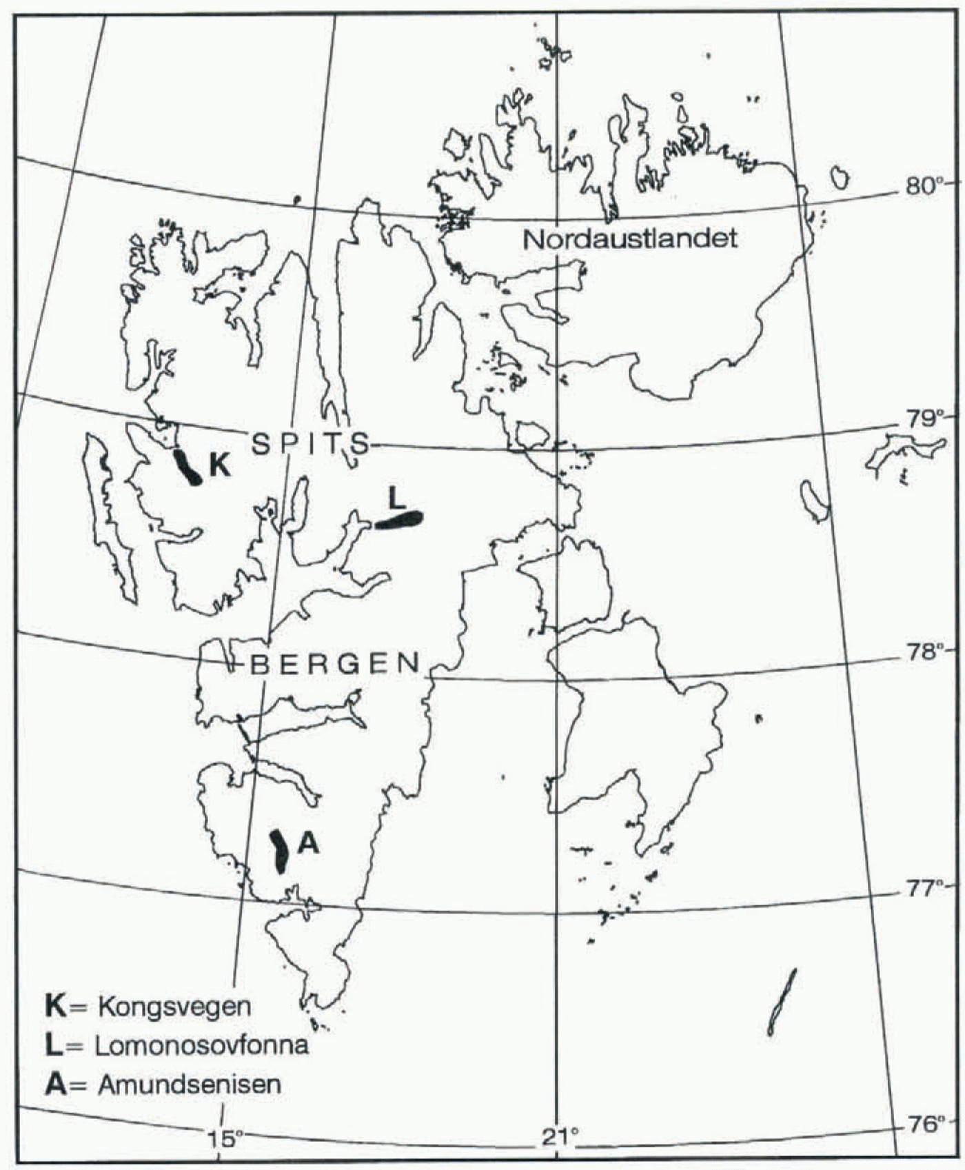
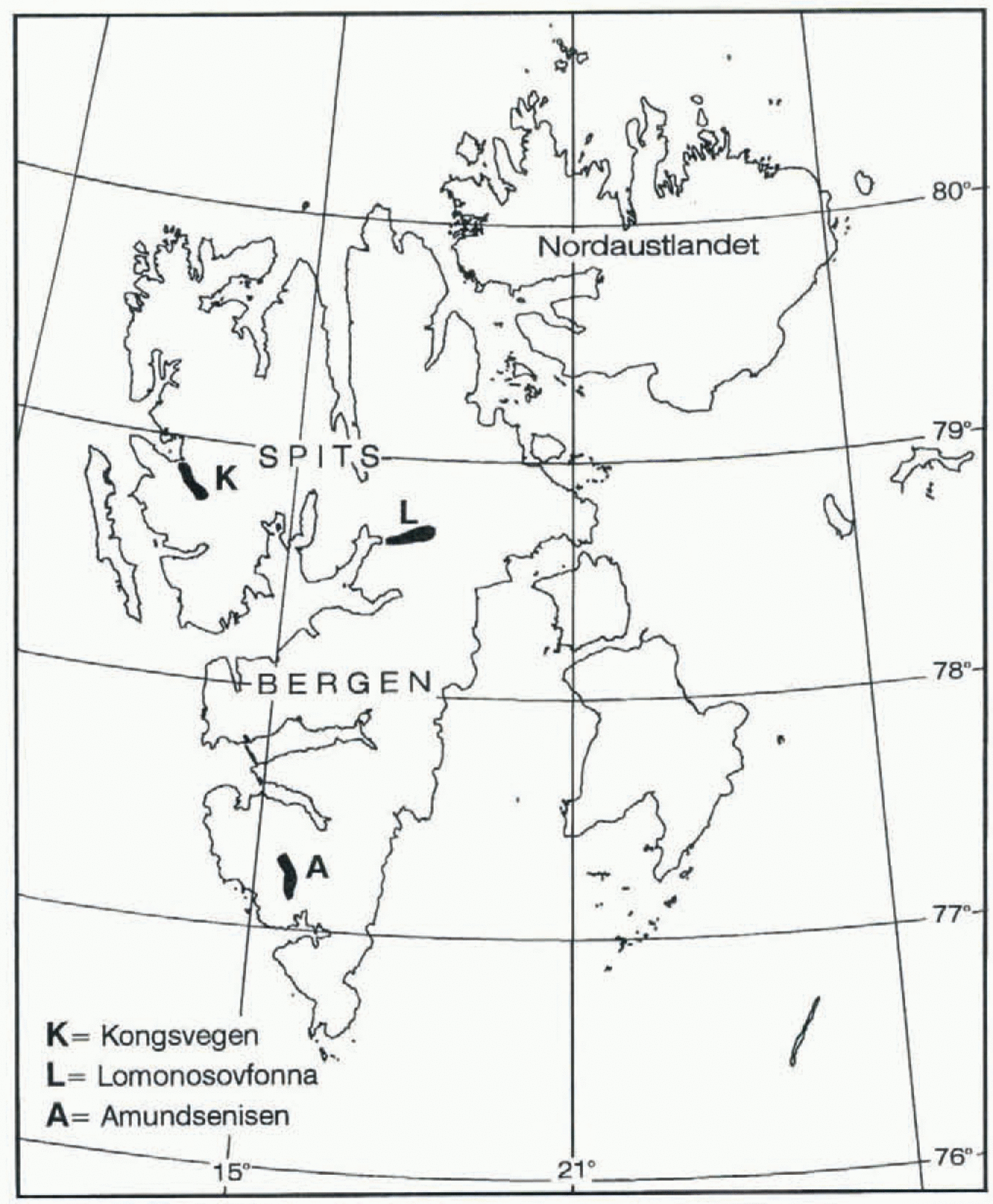
GPS survey was taken into use in Svalbard in 1991 and 1992 on a Russian–Polish–Norwegian joint project (Hagen, 1992). The aim of this project was to study the glacier dynamics, geometry changes and mass balance of three larger glaciers/ice fields in Svalbard. With background in the development of GPS techniques and the experience with the system at Norsk Polarinstitutl, Oslo, it was decided to use both static and kinematic GPS methods as part of the Norwegian contribution to the project. The idea was to see if the technique could be used on large glacier fields (A 100 km2) where traditional surveying is difficult and direct mass-balance measurements are too time-consuming and expensive. Three ice fields were selected in Spitsbergen: Amundsenisen (100 km2) in south Spitsbergen, Lomonosovfonna (240 km2) in central Spitsbergen, and Kongsvegen (105 km2) in northwest Spitsbergen (Fig. 1). The three basins are representative for large parts of the glaciated areas in Spitsbergen. They cover different altitude spans and different precipitation zones. Kinematic GPS technique was used to establish 20–25 km longitudinal altitude profiles along the central flowline on both Lomonosovfonna and Amundsenisen in 1991 and on Kongsvegen in 1992.
The use of kinematic GPS for glacier profiling was a pilot project, as both the use on a rough surface like a glacier, and difficult ionospheric conditions in Svalbard could render the project impossible. Svalbard is within a zone of high ionospheric activity, causing possible difficulties for GPS observations. The ionosphere affects the propagation of the GPS signals, and can cause considerable “noise” and cycle slips to the phase measurements, and be a limiting factor in computing the results.
The measurements were carried out in a similar way at each glacier. Close to each glacier a reference point was established on rock. The coordinates of the point were calculated
Location map of Svalbard showing where kinematic GPS surveys have heen conducted in Spitsbergen:
from GPS code positions, as the required absolute accuracy for a reference point is only better than 10 m. Three Ashtech XII, dual-frequency, GPS receivers were available. Data from the receivers were downloaded to notebook computers in the field.
The GPS measurements were performed using two methods: (1) Static GPS survey of stakes drilled into the ice was used for flow-velocity and emergence-velocity measurements.
(2) Kinematic GPS survey was used to measure stake positions and longitudinal profiles of surface elevation between the stakes.
In the following only the survey of Kongsvegen will be described.
Static measurements
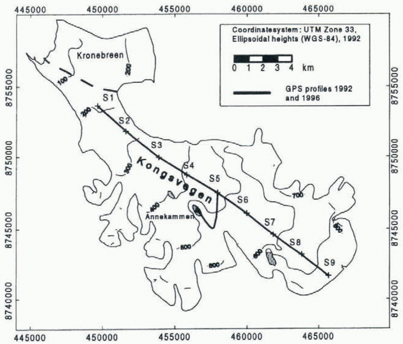
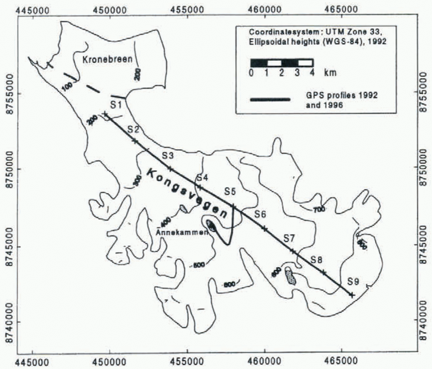
Marker stakes were placed on the glacier surface along a longitudinal profile, with 2.5 km intervals (Fig. 2). The stake positions were measured in short static sessions (1–2 h observation time), to give the best possible accuracy of coordinates at a given time. All but one of the static measurements were made relative to the selected reference point. One stake was measured only relative to a reference point 20 km away as one receiver failed. The results of flow and emergence velocity require later remeasurement. The static results should also be a control of the accuracy of the kinematic survey, and could also, if necessary, serve as known coordinates if a reinitialisation were necessary during the kinematic survey. To serve as initialisation points for a kinematic survey, the accuracy of the stake positions relative to the reference station should preferably be better than 1 cm. For kinematic initialisation, the position of stakes calculated from the static measurements would only be usable within a short time-span between static and kinematic measurements, owing to the constant glacier flow. The accuracy of the static measurements would also be on the limit for use for reinitialisation.
Kongsvegen with stake positions (S1–S9) and the location of the GPS profiles taken in 1992 and remeasured in 1996. The reference point is at Annekammen.
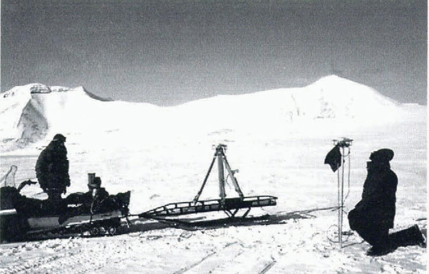
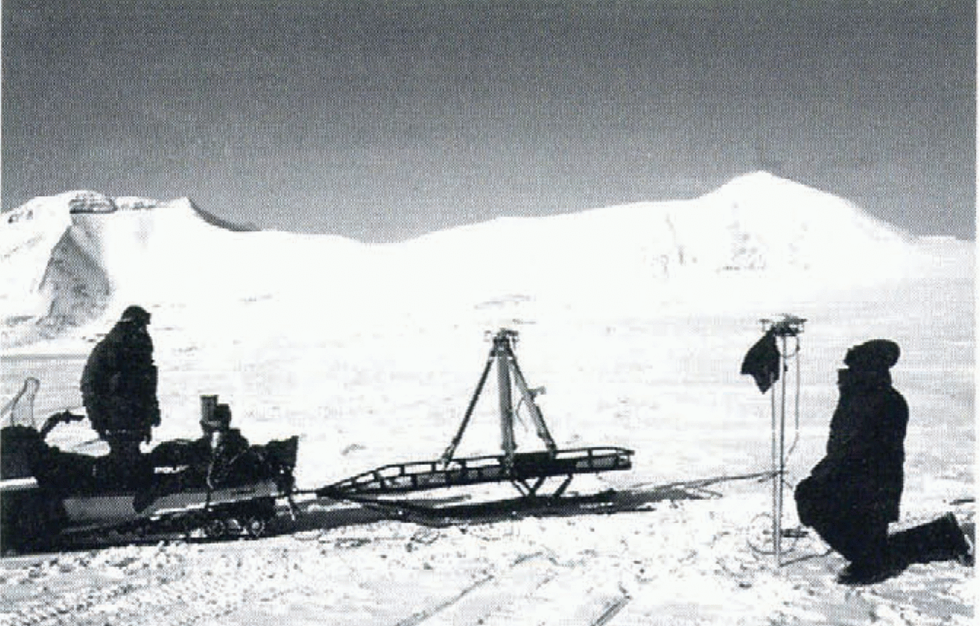
Kϊnematic GPS is carried out with one receiver transported on the sledge and one receiver permanently on a fixed point. The picture shows an antenna swap at the end of a profile where one receiver was logging continuously and worked as a second reference point.
Kinematic measurements
The kinematic measurements were performed with three receivers: one at the reference point, one at a stake in the profile where the measurements should change direction or end, and one carried on a Skidoo sledge (figs 2 and 3).
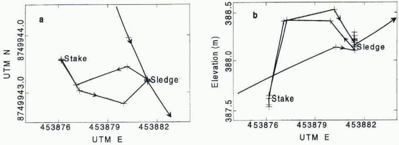
The measurements started with an antenna swap between the reference point and an established swap point nearby. After completion of the initialisation, the rover receiver was moved to a Skidoo sledge where the antenna was mounted on a tripod (Fig. 3). The sledge was towed along a profile, passing close to the established stakes. At each stake, a short stop was made, and the antenna was moved from the sledge to the stake, and approximately 1 min of data was collected at the stake (Fig. 4). The profiling continued to the stake where the third receiver was logging. At this stake, an antenna swap was completed, and the profiling was repeated backwards to the starting reference station where another antenna swap was performed. The idea of measuring the stakes was both to fix the stakes’ coordinates for control and verification of accuracy, and to enable a reinitialisation if a loss of count on satellites occurred (cycle slip). The measurements could then be continued by turning back to the last stake which was visited where observations for 1 min would give a new initialisation. The receiver at the end of the profile also enabled a new initialisation if difficulties occurred, as this receiver during the session was linked to the fixed reference station with a static vector. The “end” receiver could also be used as a reference for an independent alternative calculation of the rover positions.
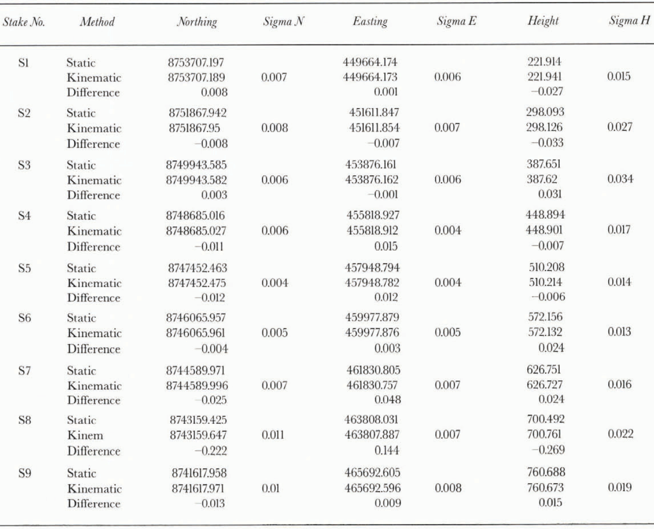
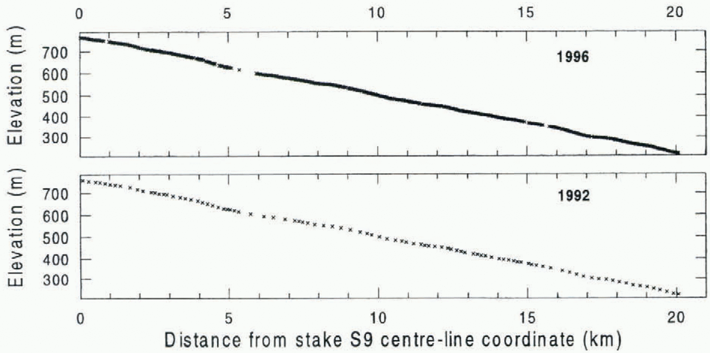
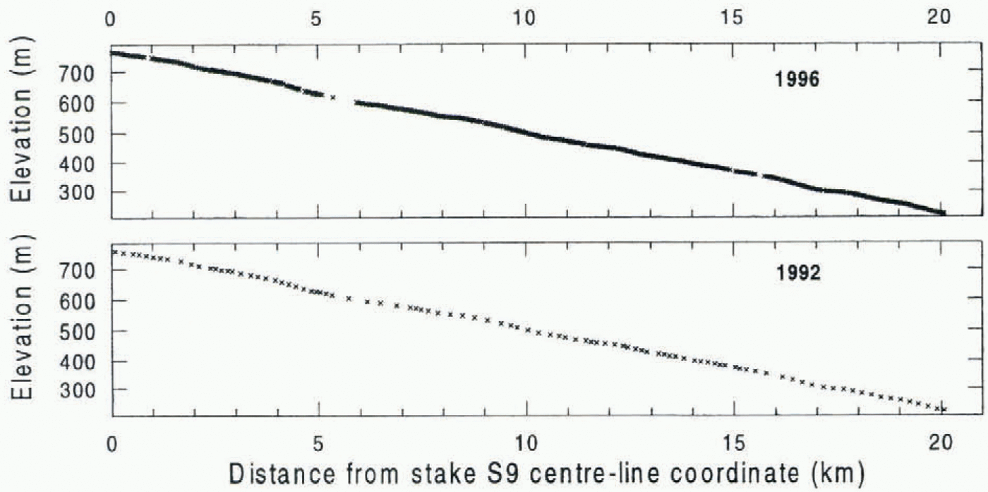
The results were calculated using Ashtech’s PNAV (Precise NAVigation) software (Ashtech Inc., 1994). This is a Kalman-filter based program for kinematic and static surveys. PNAV includes OTF solutions on full carrier dual-frequency data, and is able to repair cycle slips in single-frequency data. The calculated static and kinematic positions of the stakes are shown in tables 1 and 2. The surveyed kinematic profiles are shown in Figure 5. The coordinates were transformed to a “centre-line coordinate system” with x axis following the longitudinal profile from 1992. The elevations are WGS-84 ellipsoidal heights.
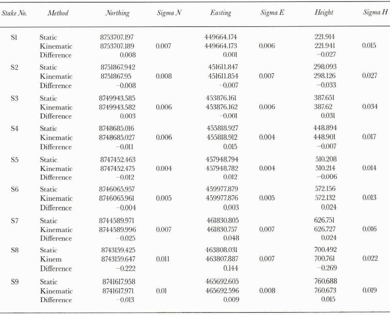
Differences between static and kinematic GPS-surveyed coordinates in 1992
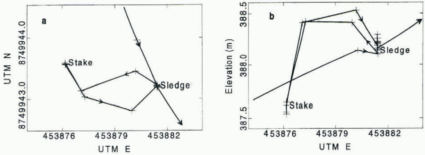
Example of how an antenna swap is logged. (a) Horizontal displacement of the antennae from the rover antennae (sledge) to the stake; and (b) vertical displacement. Note the different scales on the axis in both (a) and (b). The figure gives an impression of the accuracy of the GPS.
Measured surface elevations along Kongsvegen in spring 1992 and spring 1996 by kinematic GPS. Note the different points density of the two profiles, and the gaps in data where cycle slips occurred.
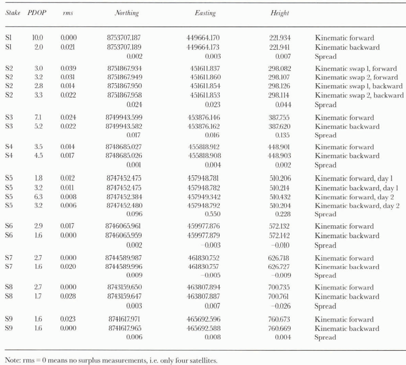
Comparisons between all kinematic stake-position measurements
In May 1996 the profile on Kongsvegen, measured in May 1992, was remeasured (Fig. 5) and gave us the possibility of seeing how well a ground-based GPS survey could detect elevation changes during a 4 year period. The equipment used in 1996 was two Ashtech Z12 GPS receivers with P-code capability. These new receivers in principle need no initialisation, as the P-code capability and the PNAV software can give an OTF ambiguity resolution where the first few measurements are used to calculate the rover receiver’s position relative to the reference. The measurements in 1996 used OTF initialisation both at the beginning and to correct for cycle slips during profiling. The profiling sessions started and ended with short (10–20 min) static sessions with the antenna on the sledge. During the 1996 profiling cycle slips caused reinitialising to be performed on the fly on three occasions. During the reinitialisations, the position solutions are not reliable until a new set of ambiguities has been solved. The reinitialisation lasts 10–20 epochs, or 30–60 s with the actual epoch interval of 3 s. This can be seen as gaps in the data in Figure 5. Static remeasurements have been carried out only at stakes S5 and S6.
Discussion
Comparison between static and kinematic measurements
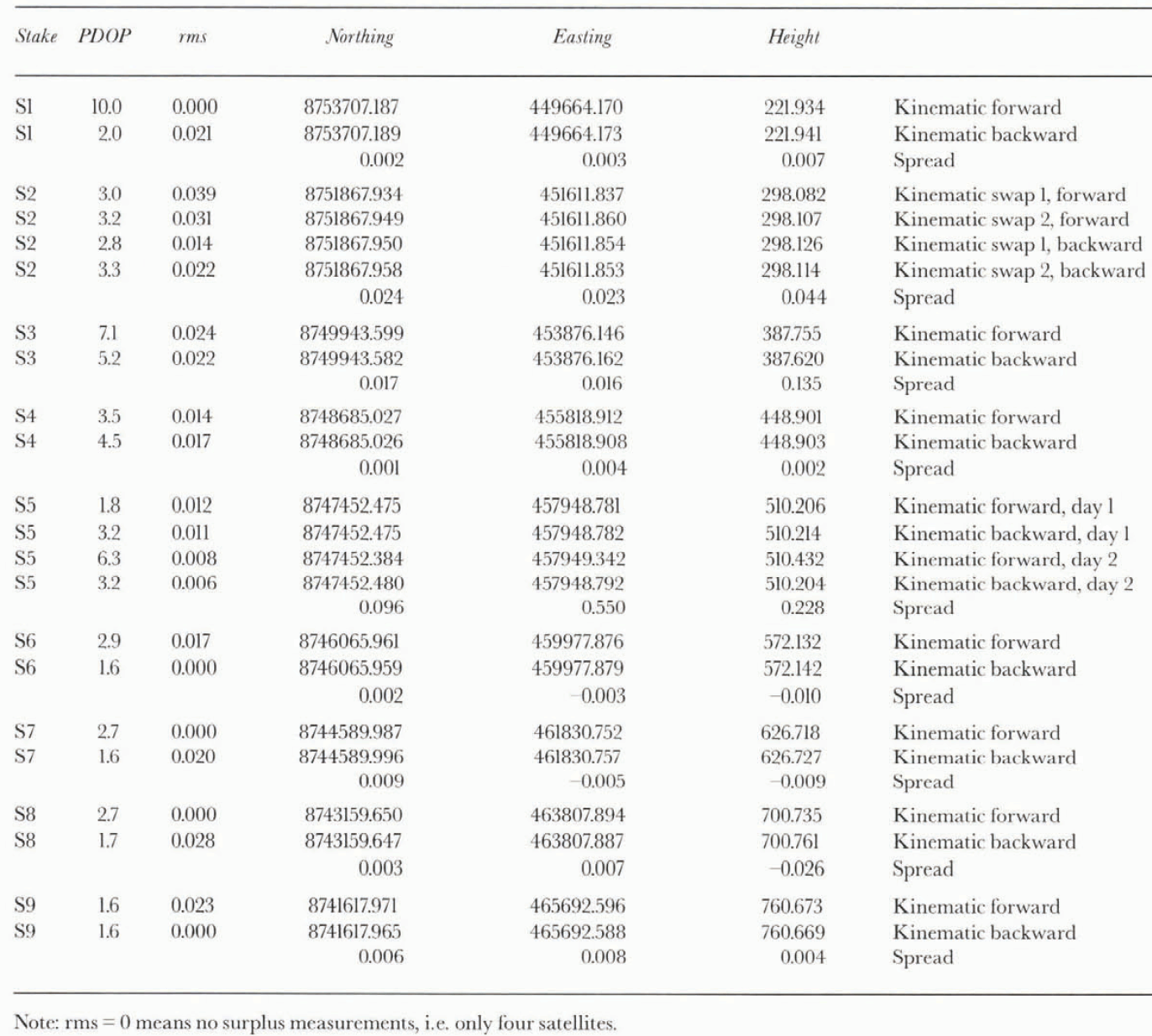
On Kongsvegen a longitudinal altitude profile about 20 km long close to the centre line from a starting-point at 750 m a.S.l. down to about 200 m a.s.I. has been calculated from kinematic GPS measurements. In addition, nine stake positions (S1–S9) along the profile have been calculated from static GPS measurements. Based on both the difference between the static and kinematic position of stakes (table 1), and the forward and backward kinematic measurements of the same (table 2), accuracies of Ã5 cm in horizontal and Ã10 cm in height seem to have been achieved for most of the stake positions. Table 1 lists the difference between static and one of the kinematic positions. The ones with lowest estimated standard errors (σ) have been selected, but as can be noted from Table 2, where all the kinematic slake measurements are listed, only two positions are more than 10 cm apart. Both the outliers were measured during periods when the geometry between the receivers and the satellites was poor (PDOP>5). The sigmas of the averaged positions were high, about 10 cm, which is more than ten times the normal sigma of less than l cm, clearly denoting that something was wrong (sigmas are not listed in Table 2).
One problem when interpreting the results is that sigmas are only calculated on static sites (at stakes). Along the track, only the rms (root mean square), number of satellites, PDOP and a quality indicator are available. The rms is, as can be seen from Table 2, not a good measure of quality. Both the bad positions of Stakes S3 and S5 are listed with low rms, giving no indication of the erroneous position. By using the other indicators, however, erroneous data can be identified.
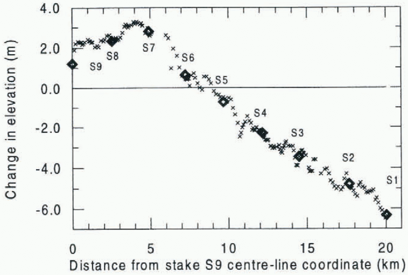
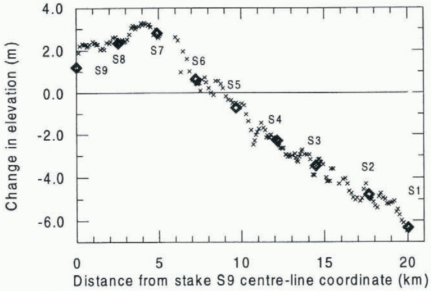
Surface elevation change along the GPS profile at Kongsvegen during the 4 year period 1991–95. The change is relative to the summer surface 1991. Thinning assured below stake S5 and thickening assured above stake S5.
Data from periods with PDOP above 5 and less than five tracked satellites should be examined especially carefully. The 1996 results have a higher level of accuracy since no periods of high PDOP were used, and the number of satellites available was higher, usually seven or more, while in 1992 periods with only four satellites were used.
Kinematic remeasurement of GPS profile on Kongsvegen
The change in surface elevation on Kongsvegen along the remeasured profile could be found by subtracting the 1996 and 1992 profiles (Fig. 6). The subtraction was not carried out directly since part of the change is due to different antenna heights and different snow thickness during the 1992 and 1996 surveys. The GPS survey was carried out in May almost at the end of the accumulation season, with maximum winter snow cover. The snow cover has been measured by snow soundings verified by stake readings and snow pits along the GPS profiles in both 1992 and 1996. The difference in snow depth from 1992 to 1996 varied from about 0.10 m in the lower part to about 1 m in the upper part. The difference in antenna height was 0.18 m. The antenna height and snow thickness were subtracted from the measured elevations before the comparison was carried out. The reference surfaces will therefore be the 1991 and 1995 summer surfaces. The uncertainty in the snow measurements was estimated to 10 cm, which gave an additional uncertainty to the height accuracy of less than 10 cm obtained from the surveying.
The GPS profiles each consist of a discrete number of x, y and z coordinates along the profile. The distance between the coordinates depends on how often the position is logged and stored in the GPS receiver, and on the velocity of the Skidoo during the survey. During the 1992 and 1996 surveys, log intervals of 10 and 3 s were used, respectively, making the 1996 profile much denser in points than the 1992 profile, as can bee seen in Figure 5. The coordinates in 1996 were not measured at exactly the same spots as the coordinates in 1992, but slightly downstream or upstream. The maximum distance of the closest pairs of coordinates from 1992 and 1996 along the remeasured profiles was about 40 m and the minimum was a few centimetres. Direct point comparison could therefore not be carried out since there is an altitude difference between the measured points due to the slope of the surface. A continous surface between the measured points for each year was therefore interpolated by use of inverse distance weighting (Davis, 1986). Since most weight was put on to the nearest point during the interpolation, more or less linear interpolation of the height between coordinates was the result. In areas where large gaps in data occurred (cycle slips in Figure 5) no comparison was carried out, since the surface was interpolated from large distance between points and thus has a lower confidence. The surface slope transverse to the longitudinal profile is much lower (about 0.1°) than along the flowline (about 1.5°). Thus no transverse compensation is needed. The maximum error found between the interpolated and measured points for a given year was about 5 cm. The change in surface elevation along the profiles during the 4 year period 1992–96 was found by subtracting the two surfaces. The altitude change at the positions measured in 1992 is shown in Figure 6. The general trend shows that an altitude decrease has occurred in the lower part of the glacier below stake S5 and an altitude increase above stake S5. At the lowest remeasured point (S1) at about 200 m a.s.l. an altitude decrease of 6.2 m has occurred. The maximum increase of 2.9 m occurred close to S7 at about 630 m a.s.l. At the highest part of the glacier, at S9, 760 m a.s.l., the increase was 1.1 m. This pattern fits very well with the accumulation and ablation measurements carried out for the mass-balance calculations. The maximum snow accumulation occurs 2–5 km downstream from the highest flat part at S9, probably due to wind redistribution of the snow.
The change of surface elevation at a given point on the glacier is given by Δh ≠ b – w where b is the net mass balance and, w is the emergence velocity (Paterson, 1994). When Δh ≠ 0 the surface geometry will change. In our kinematic profile measurements we have measured the elevation change or the net result Δh. Thus we need measurements of the emergence velocity in addition to the elevation changes to be able to use this method for mass-balance calculations along the altitude profile. Therefore, both the kinematic altitude profile and the static measurements of the stakes are needed. The emergence velocity can be measured by static measurements of the stakes. Our results show that the emergence velocity is too small to compensate for the ablation and accumulation at the surface. Thus the glacier geometry changes, building up in the accumulation area and decreasing in the ablation area. This indicates an unstable glacier that may build up towards a surge advance.
Conclusions
The main conclusion is that the GPS survey can be applied to measure geometry changes on glaciers. The results achieved from the test profiles in Svalbard are close to the theoretical accuracy, even though conditions in Svalbard can be difficult. The conclusion from the measurements in 1992 and 1996 is that the kinematic GPS survey gives the required accuracy and can thus be applied as a new method for measuring glacier surface changes and be a very useful tool in the monitoring of glacier net mass-balance changes over some years. However, careful processing is required; sampling intervals are recommended to be as short as 3 s, and measurements must be carried out in periods with more than five available satellites and good geometry between satellites and receivers, i.e. PDOP <5. When this is fulfilled the kinematic profile can be established with an accuracy better than 9 ± 5 cm in horizontal position and + 10 cm in vertical (altitude).
The results from the remeasured profile on Kongsvegen show that this glacier has a changing geometry with gradual lowering of the surface below the equilibrium line and gradual increase in the accumulation area. This indicates that this glacier is unstable and may build up to a surge advance. A correct interpretation of the results requires measurements of the emergence velocity in addition to elevation changes.
The remeasurements also showed that it is very important to follow exactly the same route on the glacier to avoid errors due to local surface undulations on the glacier. For future remeasurements of profiles it is therefore recommended that RTK be used, whereby data are transmitted by radio link from the reference station to the rover where the differential position can be computed in near real time. Thus the same track can more easily be followed on the glacier.
Acknowledgements
This paper is a contribution to the joint Russian–Polish–Norwegian project on geometry changes on Svalbard glaciers. We are grateful to A. Glazovskiy, M. Moskalevskiy and E. Zinger from the Institute of Geography, Russian Academy of Sciences, who participated in the fieldwork and organised the work on Lomonosovfonna. J. Jania, P. Glowacki and L. Kolondra, of the University of Silesia in Poland, participated from the Polish side. We also wish to express thanks to the Polish polar station in Hornsund, Svalbard, for their hospitality during the fieldwork on Amundsenisen. B. Lytskjold and B. Luktvasslimo from Norsk Polarinstitutt participated in the fieldwork and conducted an important part of the GPS measurements. G. Vatne of the Department of Geography, University of Oslo, assisted in the fieldwork. Additional support was provided by the EU Environment Programme through grant EN5V-CT93-0299.