1 Introduction
Vortex formation and shedding from a wing undergoing unsteady motions remains an issue of central importance in aerodynamics. In particular, understanding the details of the leading-edge vortex (LEV) dynamics associated with rapidly manoeuvring wings in a fluid flow has been a sturdy source of motivation for scientists interested in understanding the physics behind flapping flight and swimming in nature (Wang Reference Wang2005; Lauder Reference Lauder2015). Characterisation of the LEV dynamics, however, is difficult, not only because the physical mechanisms governing the growth and separation of an LEV are not entirely understood, but also because the LEV’s main characteristics (i.e. stability, formation time and circulation) change conspicuously as the flow conditions vary. Without a unified framework in which to characterise the LEV formation process, it is quite challenging, if not impossible, to predict and control the formation, growth and subsequent separation of an LEV for a given flow configuration.
While numerous studies have shown that the LEV dynamics is very sensitive to arbitrary variations in wing trajectories, planform shape, Reynolds number and so forth, the general consensus in the archival literature is that wing rotation plays an important role in the stabilisation of the LEV. While stationary or purely translating wings in a uniform flow are prone to stall at large angles (Bisplinghoff, Ashley & Halfman Reference Bisplinghoff, Ashley and Halfman1957; Dickinson & Gotz Reference Dickinson and Gotz1993), the existence of a stably attached LEV has been observed on rotating and pitching wings at post-stall angles (Lentink & Dickinson Reference Lentink and Dickinson2009; Hartloper & Rival Reference Hartloper and Rival2013; Wong & Rival Reference Wong and Rival2015; Onoue & Breuer Reference Onoue and Breuer2016). The stabilisation of the LEV on a rotating wing is commonly attributed to spanwise transport of vorticity arising from large rotational (centrifugal and Coriolis) accelerations – a mechanism believed to balance the flux of vorticity transported into the vortex at the leading edge so as to maintain a quasi-equilibrium state of the LEV (Lentink & Dickinson Reference Lentink and Dickinson2009; Harbin, Sheridan & Thompson Reference Harbin, Sheridan and Thompson2013). However, due to a number of competing observations, the precise correlation between rotational accelerations, wing kinematics, planform geometry and LEV stability remains obscure. For instance, it has been demonstrated by Jones, Pitt-Ford & Babinsky (Reference Jones, Pitt-Ford and Babinsky2012) that even large rotational accelerations do not necessarily lead to improved LEV stability for waving kinematics over a range of Reynolds numbers. The results of Beem, Rival & Triantafyllou (Reference Beem, Rival and Triantafyllou2012) suggest that a nominally two-dimensional spanwise flow induced by the leading-edge sweep as high as
 $45^{\circ }$
do not contribute to the LEV stability on a purely translating wing. However, when rotation was introduced to the model with a sweptback leading edge, Wong & Rival (Reference Wong and Rival2015) demonstrated that the ‘relative’ stability of the LEV (defined as the convective speed of the LEV relative to the wing) can be improved by regulating the LEV growth via the enhancement of the spanwise vorticity transport and vortex stretching, in which the latter helps to keep the vortex size under the critical length scale of one chord length, which, once breached, the vortex must inevitably separate, as suggested by Rival et al. (Reference Rival, Kriegseis, Schaub, Widmann and Tropea2014). The finding of Wong & Rival (Reference Wong and Rival2015) reinforced the importance of rotation in the stabilisation of the LEV.
More recently, Onoue & Breuer (Reference Onoue and Breuer2016) characterised the LEV dynamics on a rapidly pitching plate over a wide range of flow conditions, and demonstrated that the LEV circulation and formation time scale uniformly with the feeding shear-layer velocity at the leading edge, i.e.
 $U_{SL}=4fc\unicode[STIX]{x0394}\unicode[STIX]{x1D6FC}/2+U_{\infty }\sin (\unicode[STIX]{x1D6FC}(t))$
, where
 $f$
,
 $c$
and
 $\unicode[STIX]{x0394}\unicode[STIX]{x1D6FC}$
denote pitching frequency, plate’s chord length and maximum pitching amplitude in radians, respectively. The vortex scaling proposed in Onoue & Breuer (Reference Onoue and Breuer2016) conformed very well with the concept of optimal vortex formation number originally introduced in the seminal work of Gharib, Rambod & Shariff (Reference Gharib, Rambod and Shariff1998). This offered an appealing framework for us to think about how we can potentially control and predict the strength and formation time of the LEV. Additionally, it was shown that the stability of the LEV core is governed, at least in part, by the centrifugal fluid acceleration. Specifically, we demonstrated that the axial movement of the LEV centroid during the vortex formation process scales very well with the inverse of the Rossby number (
 $Ro=U_{SL}/R_{a}f\unicode[STIX]{x0394}\unicode[STIX]{x1D6FC}$
, where
 $R_{a}$
represents the axial distance between the LEV centroid and the location of the pivot point), which describes the ratio between the centrifugal fluid acceleration and the Coriolis acceleration. As noted in Onoue & Breuer (Reference Onoue and Breuer2016), the subtle movement of the vortex core during the formation process has a significant implication on the resulting aerodynamic torque that the surrounding fluid imparts on the wing. In particular, we have shown that the precipitous decrease in the aerodynamic torque (prior to the separation of a maximal strength LEV) is a direct result of vortex drifting, which causes the centre of pressure to move closer to the axis of rotation. From the successful scaling of the LEV formation time and circulation to the precise characterisation of the LEV movement based on our new formulation of the Rossby number, the findings of Onoue & Breuer (Reference Onoue and Breuer2016) underscore the notion that the feeding shear-layer velocity is, in fact, the main characteristic velocity governing the vortex formation process on a rapidly pitching wing.
The present study aims to generalise the expression for the LEV formation number by including dependencies on leading-edge sweep angle, pivot point location, pitch rate and oscillation amplitude. The main interest here is to assess to what extent the seemingly universal critical formation number remains unchanged from the generic value of approximately 4 when subject to these variations in the kinematics and geometries of the vortex generator. As suggested by Dabiri (Reference Dabiri2009), a rigorous extension of the Kelvin–Benjamin variational principle invoked by Gharib et al. (Reference Gharib, Rambod and Shariff1998) to explain the existence of the optimal formation number for steady axisymmetric vortex rings is currently lacking for the flow configuration of the present study. Therefore, we apply the Kelvin–Benjamin variational principle to configurations of vorticity that do not form symmetry-axis-touching vortex rings to help us elucidate the underlying flow physics governing the vortex formation process on a rapidly pitching wing in a uniform flow.
On a different level, a systematic investigation into understanding the effects of planform geometry (in particular the role of the leading-edge sweep) in relation to the resulting vortex dynamics is a necessary step towards finding a plausible explanation as to why the evolution has converged on sweptback appendages for propulsion. While previous studies on pitching wings have provided some evidence that the leading-edge curvature could help mitigate early LEV separation (Taira & Colonius Reference Taira and Colonius2009) and improve lift-to-drag ratio (Hartloper & Rival Reference Hartloper and Rival2013), the precise linkage between the leading-edge sweep and fluid dynamics remains still elusive. Of central importance is to establish an aerodynamic explanation of optimal LEV stability, formation time and circulation as a function of leading-edge sweep and wing kinematics. The present study addresses this problem and we believe that it resonates synergistically with the goal of generalising the concept of optimal vortex formation for arbitrary vortex generator geometries and flow conditions.
Furthermore, we provide quantifiable insights into the three-dimensional vorticity dynamics that accompanies the evolution of the LEV to help us better understand to what extent, if at all, the LEV associated with a nominally two-dimensional rectangular planform (e.g.
 $AR=5$
) can be justifiably modelled or approximated as quasi-two-dimensional. A number of previous investigators (e.g. Jardin, Farcy & David Reference Jardin, Farcy and David2012; Kriegseis, Kinzel & Rival Reference Kriegseis, Kinzel and Rival2013) have generalised that the central portion of the LEV (sufficiently far from the tip) can be approximated as quasi-two-dimensional – so long as the vortex reveals a certain degree of spanwise uniformity in its circulation, cross-sectional area, centroid location, etc. However, the spanwise invariance of such vortex properties – which are all planar (2D) by definition – says nothing about the intrinsic three-dimensionality of the LEV core, and therefore, it should be noted that the two-dimensional flow approximation is only appropriate if the magnitude of
 $(\unicode[STIX]{x1D74E}\boldsymbol{\cdot }\unicode[STIX]{x1D735})\boldsymbol{u}$
, i.e. the so-called ‘vortex-stretching’ term, is also demonstrably small such that the corresponding kinematics of vortex filaments that comprise an LEV do not give rise to significant three-dimensional vorticity transport phenomena. The present study attempts to make a clear distinction between nominally 2D versus 3D flows, while providing a detailed literature review on the effects of spanwise end conditions on the evolution of LEVs (e.g. Jardin et al.
Reference Jardin, Farcy and David2012; Kriegseis et al.
Reference Kriegseis, Kinzel and Rival2013; Kim et al.
Reference Kim, Strom, Mandre and Breuer2017; Visbal & Garmann Reference Visbal and Garmann2017).
In short, the objectives of the present investigation are threefold: (1) characterise the dynamics and stability of an LEV with variations in geometry and kinematics of the vortex generator, (2) quantify the relative importance of two- and three-dimensional vorticity transport mechanisms to the overall LEV circulation growth, and (3) propose and validate generalised LEV scaling parameters for swept and unswept pitching wings.
2 Experimental techniques
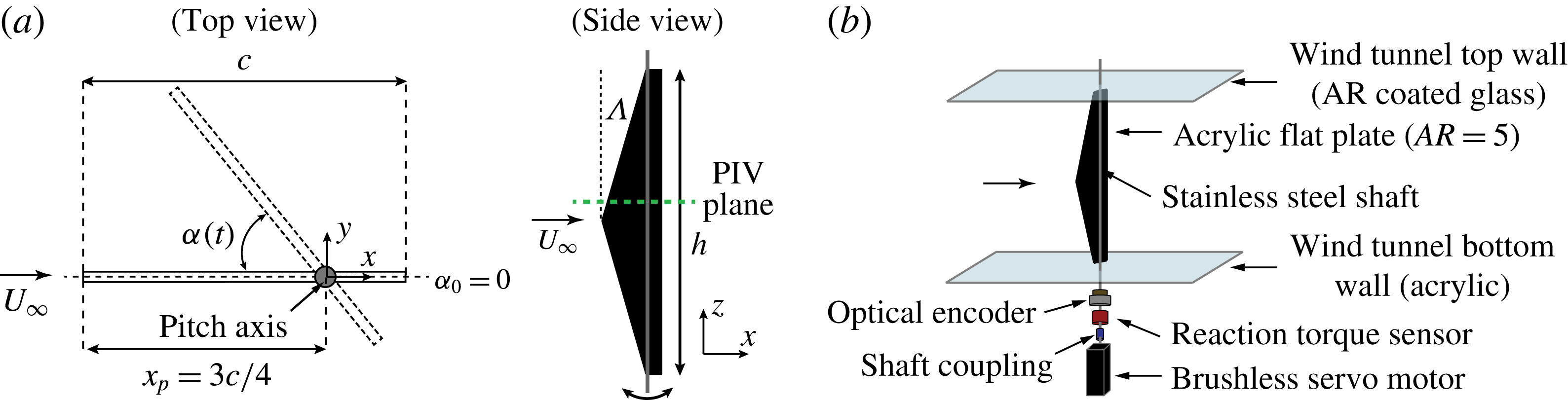
All experiments were carried out in a closed-loop, low-turbulence wind tunnel with a test section of 0.6 m in width, 0.6 m in depth, and 1.2 m in length. The turbulence level in the wind tunnel was measured to be less than 0.1 % of the free-stream velocity. Figure 1(a) illustrates a flat-plate model used in the present study, with maximum chord,
 $c=0.1$
m, span,
 $h=0.5$
m and thickness,
 $\unicode[STIX]{x1D6FF}=3$
mm, exposed to a uniform free stream of magnitude,
 $U_{\infty }$
, and density,
 $\unicode[STIX]{x1D70C}_{f}$
. The Reynolds number based on the chord length,
 $Re=U_{\infty }c/\unicode[STIX]{x1D708}$
, was fixed at
 $1.03\times 10^{5}$
, where
 $\unicode[STIX]{x1D708}$
is the kinematic viscosity of the fluid. Three different symmetric planforms tested in the present study were fabricated with leading-edge sweptback angles of
 $\unicode[STIX]{x1D6EC}=0^{\circ }$
,
 $11.3^{\circ }$
and
 $16.7^{\circ }$
, while keeping the wing span and maximum chord length fixed, as illustrated in figure 1(a). The pivot point on all three planforms was located at a distance
 $3c/4$
from the leading edge when measured on the mid-span symmetry plane. While the chord represented roughly 16 % of the test section width, the effects of blockage and sidewall boundary layers have been previously verified to be minor, such that both the steady and unsteady aerodynamic characteristics of a flat plate remained nearly independent of the chord length (at least up to
 $c=0.15$
m), as discussed in Onoue et al. (Reference Onoue, Song, Strom and Breuer2015) and Onoue & Breuer (Reference Onoue and Breuer2016).
(a) Schematic of an oscillating flat plate (top view) with a pitch axis located at
 $3c/4$
from the leading edge at the mid-span symmetry plane. The dashed horizontal line designates the equilibrium angle of attack,
 $\unicode[STIX]{x1D6FC}_{0}=0$
; (right) a symmetric swept planform supported by the shaft along its span. The spanwise location of the particle image velocimetry (PIV) measurement is designated by the dashed green line. (b) A computer-controlled servomotor rotates the shaft-plate assembly by applying a specific torque calculated via a real-time dynamical simulation to achieve the desired structural dynamics. Refer to Onoue et al. (Reference Onoue, Song, Strom and Breuer2015) for the details of the cyber-physical system control algorithm.

2.1 Cyber-physical experimental setup
Figure 1(b) shows a schematic of the cyber-physical experimental setup implemented in the present study, illustrating the flat plate supported by a virtual mass–spring–damper system in the wind tunnel test section. The cyber-physical system is one in which the structural dynamics (i.e. torsional stiffness, damping, and mass moment of inertia) are controlled electronically rather than by physical hardware. The physical components of the cyber-physical system consist of a brushless computer-controlled servomotor (SM233AE, Parker Compumotor, Rohnert Park, CA), reaction torque sensor (TFF400, Futek, Irvine, CA), and rotary optical encoder (HB6M Optical Encoder, US Digital, Vancouver, WA). The digital controller (Simulink, Mathworks, Natick MA) samples the instantaneous angular position,
 $\unicode[STIX]{x1D6FC}(t)$
, from the encoder at 4 kHz, and numerically evaluates the velocity,
 $\dot{\unicode[STIX]{x1D6FC}}(t)$
and acceleration,
 $\ddot{\unicode[STIX]{x1D6FC}}(t)$
, in real-time using the linear-phase FIR differentiators. The position, velocity, and acceleration signals are respectively multiplied by the user-specified stiffness,
 $k_{v}$
, damping,
 $b_{v}$
, and mass moment of inertia,
 $I_{v}$
, coefficients, where the subscript
 $v$
denotes a virtual quantity. These signals are combined to determine the target motor torque,
 $\unicode[STIX]{x1D70F}_{m}(t)=I_{v}\ddot{\unicode[STIX]{x1D6FC}}(t)+b_{v}\dot{\unicode[STIX]{x1D6FC}}(t)+k_{v}\unicode[STIX]{x1D6FC}(t)$
, to be applied to the servomotor. The aerodynamic torque can be evaluated from the equation:
 $\unicode[STIX]{x1D70F}_{f}(t)=I_{p}\ddot{\unicode[STIX]{x1D6FC}}(t)+b_{p}\dot{\unicode[STIX]{x1D6FC}}(t)+\unicode[STIX]{x1D70F}_{m}(t)$
, where the subscript
 $p$
designates a physical quantity. Since the cyber-physical system does not possess a physical torsional spring (
 $k_{p}=0$
), the structural stiffness is only due to the virtual stiffness applied by the digital controller. For more descriptions of the cyber-physical system’s control architecture and the testing procedures to determine the values of
 $I_{p}$
and
 $b_{p}$
, the readers are encouraged to refer to Onoue et al. (Reference Onoue, Song, Strom and Breuer2015). However, in contrast to the work of Onoue et al. (Reference Onoue, Song, Strom and Breuer2015) who explored a range of structural stiffness and damping values, the cyber-physical system in the present investigation is employed solely for the purpose of generating sinusoidal motion with a desired amplitude and frequency. This was achieved by tuning the structural parameters (
 $k_{v}$
,
 $b_{v}$
and
 $I_{v}$
) appropriately. Although the same effect can be achieved using an open-loop control system, we used the cyber-physical system for convenience.
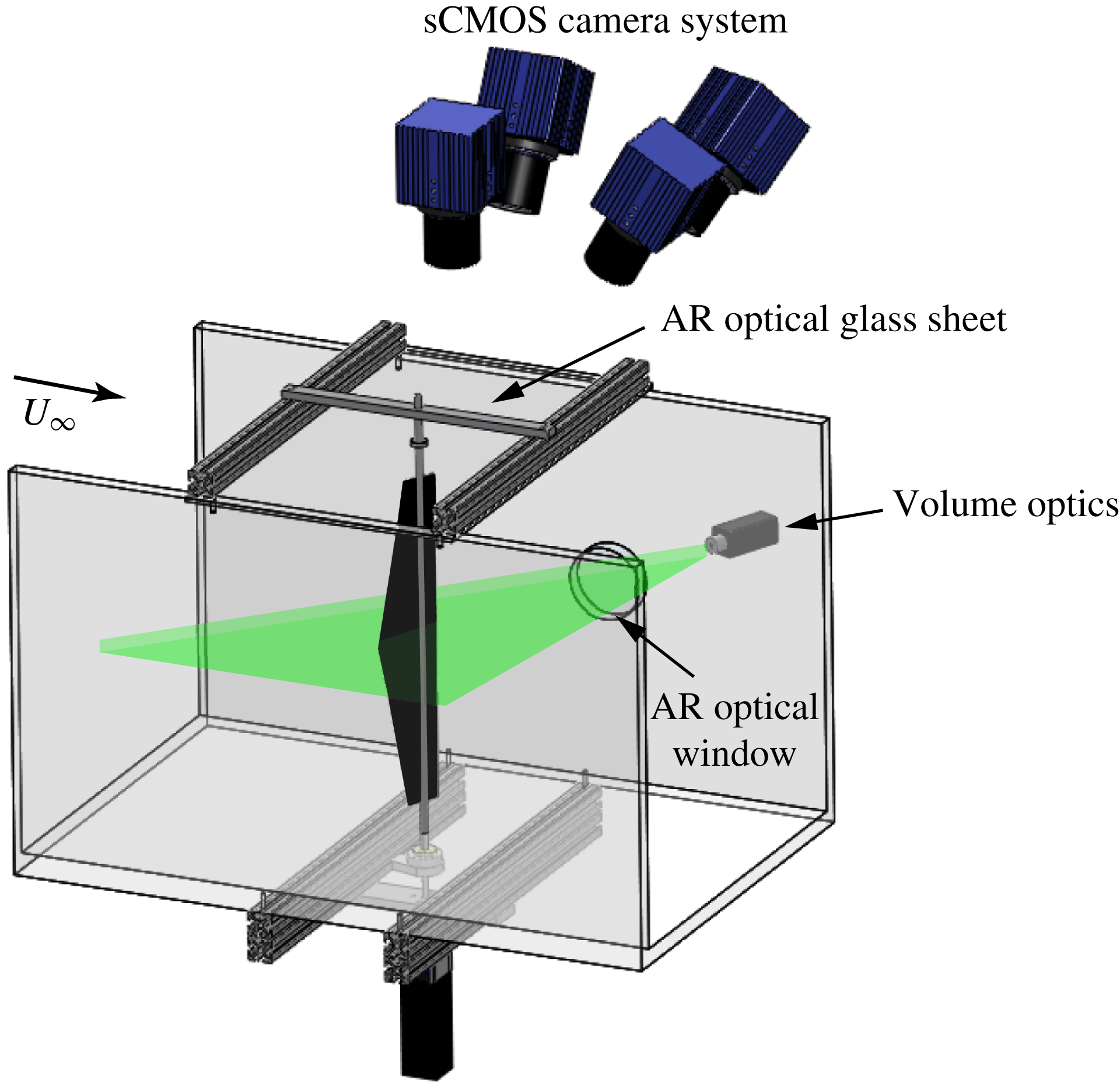
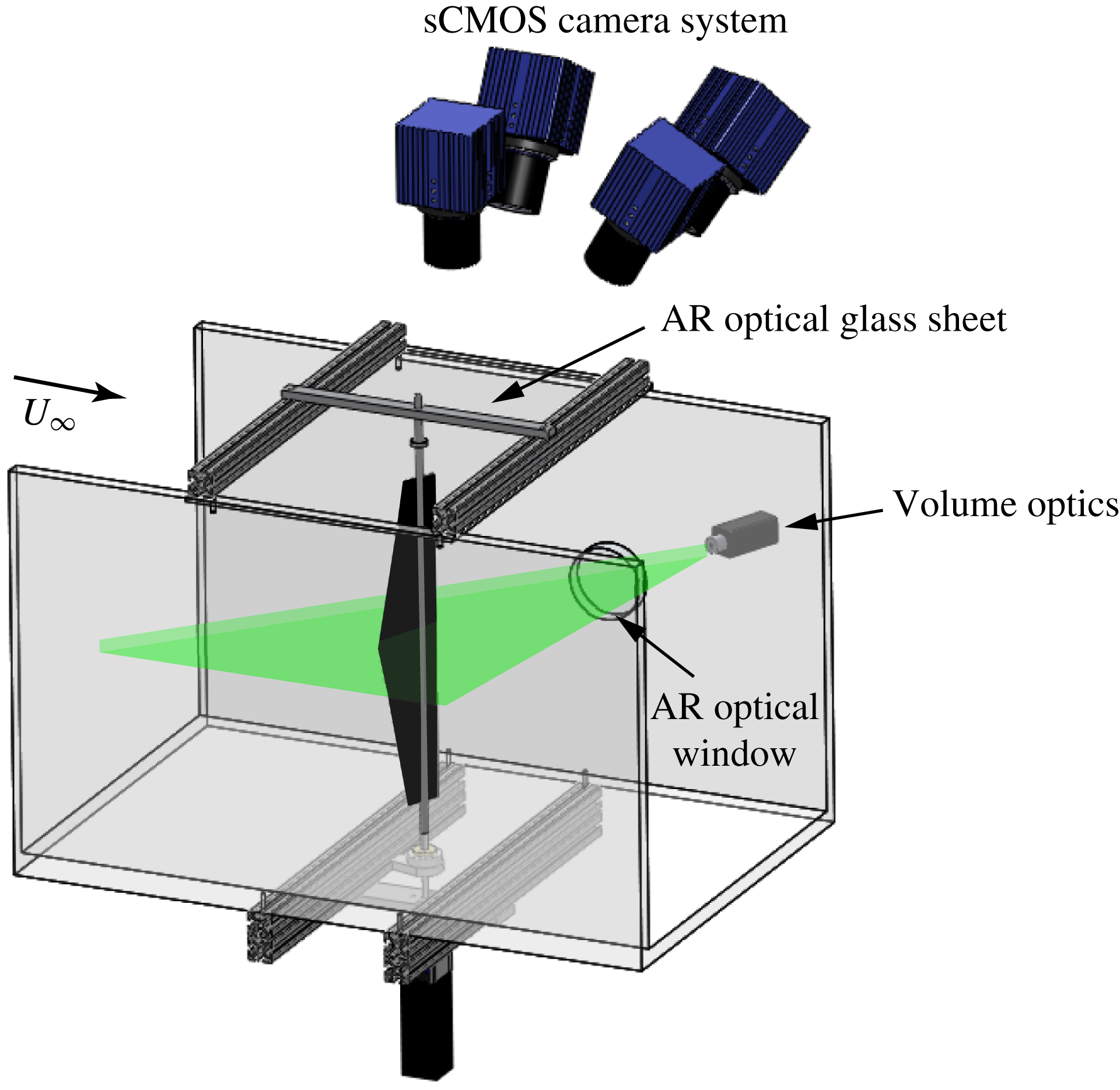
Experimental setup for tomographic PIV measurements consisting of four sCMOS cameras focused on the illumination volume from different angles.
2.2 Tomographic PIV setup and vortex identification technique
Tomographic PIV was implemented in this study to obtain a complete description of the flow field, i.e. all nine components of the velocity gradient tensor. The setup for the streamwise tomographic PIV experiment is illustrated in figure 2. All PIV measurements were acquired in the streamwise plane located at 2 cm above the mid-span symmetry plane. The wing was painted matt black to reduce reflections. A 5 mm-thick illumination volume was generated using a double-pulsed 200 mJ Nd:YAG laser (
 $\unicode[STIX]{x1D706}=532$
nm) (EverGreen, Quantel USA, MT) with LaVision sheet optics. The flow was seeded with oil droplets nominally 1
 $~\unicode[STIX]{x03BC}\text{m}$
in diameter. The particle images were acquired with four synchronised sCMOS cameras (LaVision) equipped with 50 mm lenses (Nikon) on Scheimpflug adapters (LaVision) to ensure that the image planes are aligned with the central plane of the measurement volume. Each camera has a resolution of 2560 pixels
 $\times$
2160 pixels and the frame rate for image acquisition was 15 Hz. Tomographic measurements are restricted to the region covering only the suction side of the plate and a small portion of the wake, owing to the logistical difficulty in maintaining a common field of view from all four cameras in the vicinity of a moving plate. Velocity fields were calculated using DaVis 8.1.6 software (LaVision). The particle volume reconstruction from all four camera images was performed using the fast MART algorithm. Subsequently, the three-dimensional particle intensity fields were evaluated from the reconstructed volume data to obtain the instantaneous velocity fields through a volume cross-correlation routine that utilises Gaussian weighting and 75 % overlap in multi-pass iterations with decreasing voxel size, peak search radius, and volume binning, yielding a spatial resolution of approximately 0.9 mm in
 $x$
,
 $y$
and
 $z$
directions (
 ${\approx}1\,\%$
of the maximum wing chord length). Five velocity fields were extracted from the measurement volume, each yielding a field of view measuring approximately 0.16 m by 0.2 m in the streamwise plane. Each PIV experiment constitutes 2200 velocity measurements, which were subsequently allocated into 72 uniformly spaced bins over one oscillation cycle (
 $\unicode[STIX]{x0394}\unicode[STIX]{x1D719}=5^{\circ }$
). The instantaneous phase was extracted from the angular position time trace by taking the Hilbert transform (Khalak & Williamson Reference Khalak and Williamson1999).
We employed the vortex identification technique based on the vortex swirling strength (Adrian, Christensen & Liu Reference Adrian, Christensen and Liu2000) to identify the coherent vortices within the measurement domain. The threshold was set to 10 % of the maximum swirling strength to isolate the LEVs from the background noise. This threshold was appropriate to clearly distinguish the LEV core from the feeding shear layer emanating from the leading edge. Note that the swirling strength threshold was applied only to identify the LEV boundary. The evaluation of various vortex properties (e.g. LEV circulation) and different terms in (2.2) was performed to the full velocity field without any applied threshold. The spanwise circulation of the primary vortex was calculated by integrating the simply connected vorticity patch about the vortex centroid using Stokes’ theorem. The results were insensitive to the swirling threshold values in the range of
 $0.1\pm 0.05$
. Several other vortex identification methods, including the Q criterion and
 $\unicode[STIX]{x1D6E4}_{2}$
criterion (Graftieaux, Michard & Grosjean Reference Graftieaux, Michard and Grosjean2001), were also tested, but found to yield similar results. In addition, the
 $\unicode[STIX]{x1D6E4}_{1}$
criterion was utilised to identify the position of the LEV centroid. In the present study, a threshold of
 $\unicode[STIX]{x1D6E4}_{1}\geqslant 0.9$
was selected, and the vortex centre is found where the maximum spatial value of
 $\unicode[STIX]{x1D6E4}_{1}$
is achieved.
2.3 Formulation of the LEV circulation budget analysis
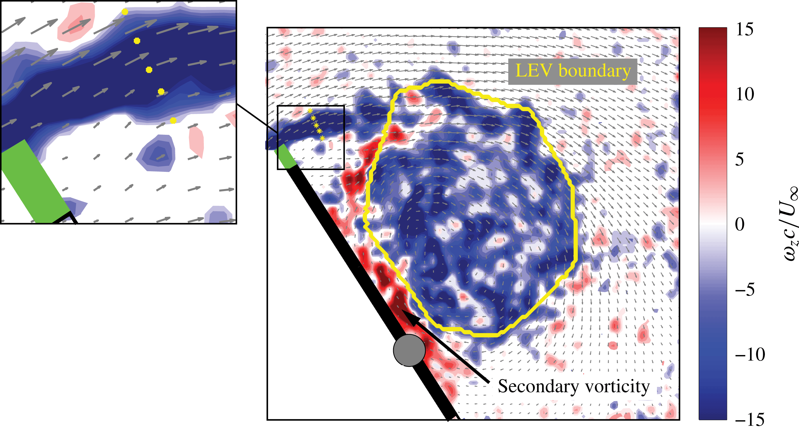
In order to examine the circulation budget of the leading-edge vortex, a series of control volume analyses are conducted over the boundary enclosing the LEV core, as depicted in figure 3. To characterise the vorticity transport inside the LEV, consider the following vorticity transport equation for an incompressible barotropic fluid with conservative body forces:
 $$\begin{eqnarray}\frac{\unicode[STIX]{x2202}\unicode[STIX]{x1D74E}}{\unicode[STIX]{x2202}t}=-(\boldsymbol{u}\boldsymbol{\cdot }\unicode[STIX]{x1D735}\boldsymbol{u})+(\unicode[STIX]{x1D74E}\boldsymbol{\cdot }\unicode[STIX]{x1D735})\boldsymbol{u}+\unicode[STIX]{x1D708}\unicode[STIX]{x1D6FB}^{2}\unicode[STIX]{x1D74E},\end{eqnarray}$$
where
 $\boldsymbol{u}=[u,v,w]$
and
 $\unicode[STIX]{x1D74E}=[\unicode[STIX]{x1D714}_{x},\unicode[STIX]{x1D714}_{y},\unicode[STIX]{x1D714}_{z}]$
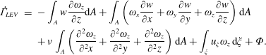
represent the three-dimensional velocity and vorticity vectors, respectively. By Stokes’s theorem, the LEV circulation is evaluated by taking the area integration of spanwise vorticity over the LEV boundary. Therefore, the expression for the rate of change of LEV circulation,
 $\dot{\unicode[STIX]{x1D6E4}}_{\mathit{LEV}}$
, is given in Cartesian form as:
 $$\begin{eqnarray}\displaystyle \dot{\unicode[STIX]{x1D6E4}}_{\mathit{LEV}} & = & \displaystyle -\int _{A}w\frac{\unicode[STIX]{x2202}\unicode[STIX]{x1D714}_{z}}{\unicode[STIX]{x2202}z}\text{d}A+\int _{A}\left(\unicode[STIX]{x1D714}_{x}\frac{\unicode[STIX]{x2202}w}{\unicode[STIX]{x2202}x}+\unicode[STIX]{x1D714}_{y}\frac{\unicode[STIX]{x2202}w}{\unicode[STIX]{x2202}y}+\unicode[STIX]{x1D714}_{z}\frac{\unicode[STIX]{x2202}w}{\unicode[STIX]{x2202}z}\right)\text{d}A\nonumber\\ \displaystyle & & \displaystyle +\,\unicode[STIX]{x1D708}\int _{A}\left(\frac{\unicode[STIX]{x2202}^{2}\unicode[STIX]{x1D714}_{z}}{\unicode[STIX]{x2202}^{2}x}+\frac{\unicode[STIX]{x2202}^{2}\unicode[STIX]{x1D714}_{z}}{\unicode[STIX]{x2202}^{2}y}+\frac{\unicode[STIX]{x2202}^{2}\unicode[STIX]{x1D714}_{z}}{\unicode[STIX]{x2202}^{2}z}\right)\text{d}A+\int _{\unicode[STIX]{x1D709}}u_{\unicode[STIX]{x1D709}}\unicode[STIX]{x1D714}_{z}\,\text{d}\unicode[STIX]{x1D709}+\unicode[STIX]{x1D6F7}.\end{eqnarray}$$
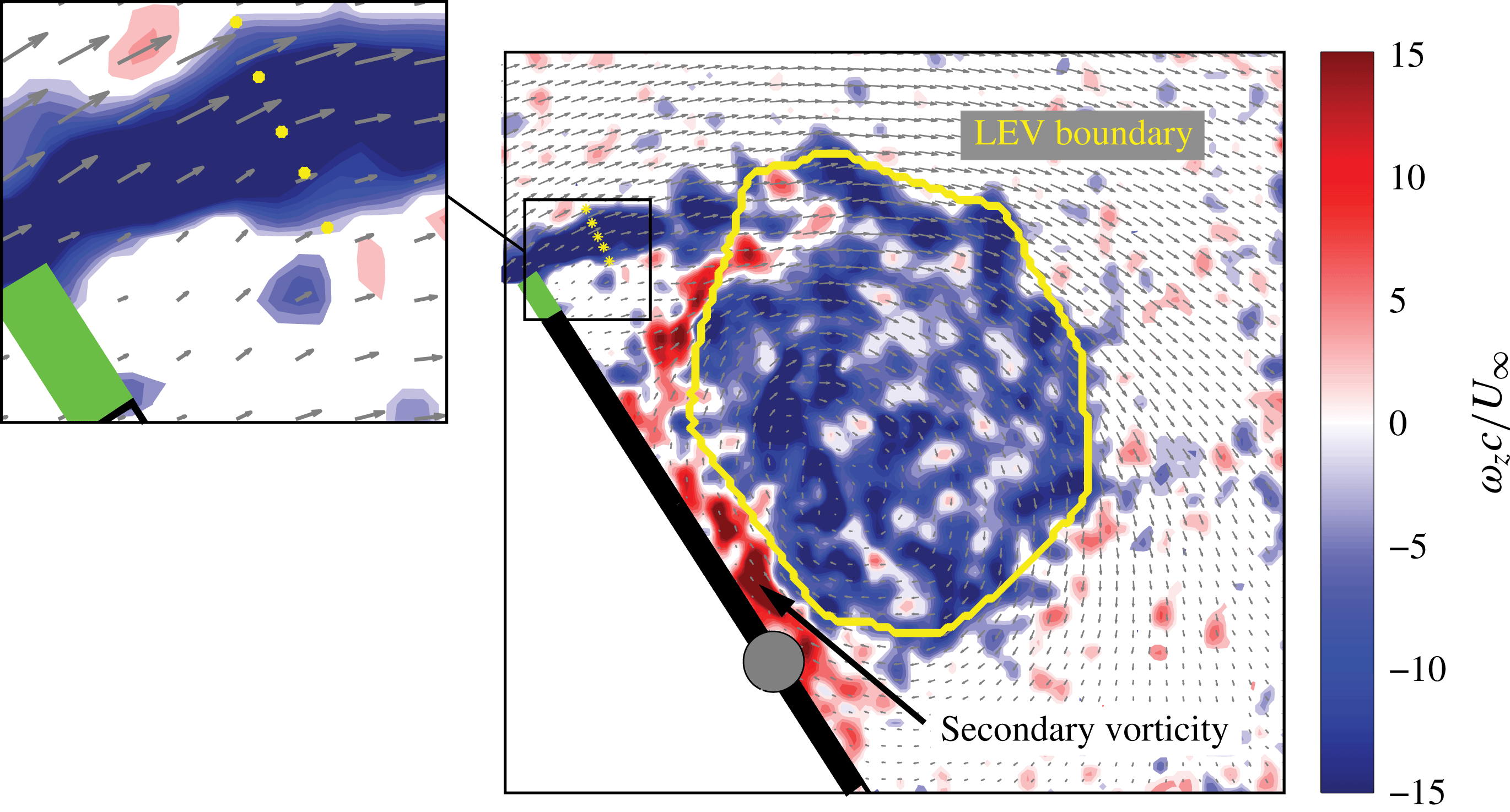
The boundary of the control volume (demarcated in yellow) encloses the outer periphery of the LEV core. Note that the boundary isolates the vortex core from the feeding shear layer. A zoomed-in view of the feeding shear layer shows samplings of the shear-layer velocity at five discrete points (yellow markers). The entrainment of the secondary vorticity from the plate surface is illustrated clearly, and the corresponding vorticity flux is captured by the last term of (2.2). Instantaneous velocity measurements are employed for the LEV circulation budget analysis.
The first term on the right-hand side of (2.2) represents the circulation flux due to spanwise convection. The second term describes vortex tilting and stretching. The physical meaning of this term can be understood by decomposing it into its symmetric (strain,
 $S_{ij}$
) and antisymmetric (rotation,
 $R_{ij}$
) components:
 $\unicode[STIX]{x1D714}_{j}S_{ij}+\unicode[STIX]{x1D714}_{j}R_{ij}$
. One can easily show that the antisymmetric component is identically zero upon expanding out the term, the equation simplifies to
 $\unicode[STIX]{x1D714}_{j}(\unicode[STIX]{x2202}u_{i}/\unicode[STIX]{x2202}x_{i})=\unicode[STIX]{x1D714}_{j}S_{ij}$
(Kinzel et al.
Reference Kinzel, Wolf, Holzner, Lüthi, Tropea and Kinzelbach2011). Given this result, one can interpret the vortex tilting/stretching term as the local amplification (or reduction) of vorticity due to the local rate of strain. Furthermore, it should be noted that vortex stretching is induced by the local convergence of mass of fluid (i.e.
 $((\unicode[STIX]{x2202}u/\unicode[STIX]{x2202}x)+(\unicode[STIX]{x2202}v/\unicode[STIX]{x2202}y))<0$
or
 $(\unicode[STIX]{x2202}w/\unicode[STIX]{x2202}z)>0$
by continuity), and that it results in commensurate amplification of the absolute vorticity to compensate for the contraction of the cross-sectional area of the vortex tube in order to preserve the vortex circulation as dictated by Helmholtz’s second theorem (e.g. Kundu & Cohen Reference Kundu and Cohen2008). Since the clockwise vorticity is taken to be negative in the present study, vortex stretching implies
 $\unicode[STIX]{x1D714}_{z}\unicode[STIX]{x2202}w/\unicode[STIX]{x2202}z<0$
. The third term approximates the circulation loss due to viscous diffusion of vorticity. The in-plane convective terms are excluded in the present formulation since the majority of fluid particles brought into the control volume through the feeding shear layer are trapped in the recirculating region bounded by the LEV boundary illustrated in figure 3. We verified that the in-plane convective terms make no significant contribution to the overall LEV circulation budget due to the fact that the magnitude of these terms is generally an order of magnitude smaller than the out-of-plane counterpart. The same observation has been reported by several researchers who evaluated the circulation budget of an LEV associated with a translating (Kim & Gharib Reference Kim and Gharib2011) and a rotating (Wojcik & Buchholz Reference Wojcik and Buchholz2014) wing. For this reason the in-plane convective terms were appropriately excluded in their formulations as well. The circulation influx due to the feeding shear layer is taken into account by the fourth term on the right, where the feeding shear-layer velocity,
 $u_{\unicode[STIX]{x1D709}}$
, is determined by sampling the velocity vectors along the line
 $\unicode[STIX]{x1D709}$
drawn approximately perpendicular to the feeding shear layer. A typical thickness of the feeding shear layer associated with the present problem is approximately 5 mm and was well-resolved by the tomographic PIV which yielded four to five discrete velocity vectors normal to the shear-layer axis,
 $\unicode[STIX]{x1D709}$
. The spatial resolution was deemed sufficient, and compared well to that of Sattari et al. (Reference Sattari, Rival, Martinuzzi and Tropea2012), who had higher spatial resolution (
 ${\approx}$
0.25 mm), but had to resolve a thinner shear layer (2 mm) that had both positive and negative vorticity, compared to the thicker layer with only single sign of vorticity in the present case. Finally, the term
 $\unicode[STIX]{x1D6F7}$
estimates the flux of secondary (positive) vorticity advected into the LEV from the surface of the plate, as depicted in figure 3. This term accounts for the circulation reduction owing to vorticity destruction, bearing a similar role as the vorticity annihilation term introduced by Wojcik & Buchholz (Reference Wojcik and Buchholz2014). We estimate the magnitude of
 $\unicode[STIX]{x1D6F7}$
by calculating the difference between the two values of
 $\dot{\unicode[STIX]{x1D6E4}}_{\mathit{LEV}}$
obtained by including and excluding the secondary vorticity inside the LEV boundary, where
 $\dot{\unicode[STIX]{x1D6E4}}_{\mathit{LEV}}$
is approximated using a fourth-order-accurate finite differencing scheme. Note that this is a different approach than the one taken by Wojcik & Buchholz (Reference Wojcik and Buchholz2014), where the annihilation term was simply equated to the residual in the vorticity balance. The annihilation term is evaluated under the assumption that any positive vorticity inherent in the vortex core originates from the surface vorticity layer. In the current geometry, the intrusion of the surface vorticity layer into the vortex core (i.e. the control volume) is quite clear (e.g. figure 3).
Eslam Panah et al. (Reference Eslam Panah, Akkala and Buchholz2015) estimated the annihilation term by integrating the pressure gradients along the wing surface, where the authors employed a rectangular control volume whose bottom boundary coincides with the surface of the wing. Because this control volume does not objectively demarcate the boundary of the LEV core, however, the present approach may pose some challenges. First, it should be noted that the pressure distribution on the wing (and thus the pressure gradient,
 $\unicode[STIX]{x2202}P/\unicode[STIX]{x2202}x$
) is influenced not only by the secondary (red) vorticity layer, but also by the presence of the LEV in close proximity, whose circulation and stability (i.e. the vortex location relative to the wing surface) are expected to have a significant impact on the integral value of
 $\unicode[STIX]{x2202}P/\unicode[STIX]{x2202}x$
. Because the circulation and stability of an LEV are presumably governed by a number of vorticity transport mechanisms (i.e. spanwise convection, shear-layer flux, etc), as clearly entailed by the circulation budget equation, one could argue that the surface pressure gradient term in (7) of Eslam Panah et al. (Reference Eslam Panah, Akkala and Buchholz2015) does not, strictly speaking, represent or quantify the rate of change of LEV circulation due, exclusively, to the influx of secondary vorticity. Secondly, it should be noted that a significant portion of the integration boundary (as depicted in figure 6 of Eslam Panah et al.
Reference Eslam Panah, Akkala and Buchholz2015) is adjacent to the primary (blue) vorticity layer, which, in principle, should not be accounted in the evaluation of the annihilation term. We believe that the approach proposed by us in this study that makes a use of the control volume bounded by the periphery of the LEV core – as in the work of Wojcik & Buchholz (Reference Wojcik and Buchholz2014), but without having to forcefully equate both sides of the circulation budget equation to derive an estimate for the annihilation term – provides a fair approximation of the annihilation term.
All the quantities on the right-hand side of (2.2) are evaluated at the central PIV plane, and the spatial derivatives and all three components of the vorticity vector are approximated using a fourth-order-accurate, five-point stencil finite differencing scheme that incorporates the velocity measurements at four neighbouring spanwise planes. The rate of change of LEV circulation on the left-hand side of (2.2) is computed by calculating the vortex circulation at discrete times, and evaluating the corresponding rate of growth using a fourth-order-accurate finite difference approximation in time.
3 Results and discussion
3.1 LEV dynamics and stability
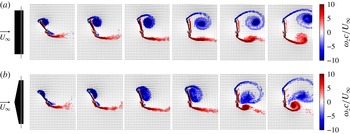
As stated earlier, one of the objectives of the present investigation is to help us better understand how the geometry of the wing planform influences the resulting vortex dynamics. Figure 4 compares the LEV dynamics associated with rectangular (a) and swept (b) planforms undergoing large-scale oscillations. The two LEVs exhibit markedly distinct characters in terms of vortex shape, size, stability and circulation. Of our particular interest is to find an explanation for the prolonged LEV attachment on the swept planform by drawing attention to the three-dimensionality of the fluid motion inside the LEV as well as the movement and energetics of the LEV core that may influence the behaviour of vortex formation, growth and subsequent separation.
Sequential snapshots of spanwise vorticity fields (measured using PIV) illustrating the formation, growth, and shedding of the LEVs on a rectangular planform (a) and a sweptback planform with a leading-edge sweep angle of
 $12^{\circ }$
(b). The Reynolds number (
 $Re=10^{5}$
) and wing kinematics are comparable in both cases, where the pitching amplitude and the reduced frequency are approximately
 $83^{\circ }$
and 0.15, respectively. Pivot axis is located at
 $3c/4$
from the leading edge.

First, we examine the stability of the LEV to better characterise the mechanism responsible for the subtle movement of the LEV core on a rapidly pitching wing. A wide range of flow conditions is considered by systematically modulating the reduced frequency (defined as
 $f^{\ast }=\unicode[STIX]{x03C0}fx_{p}\unicode[STIX]{x0394}\unicode[STIX]{x1D6FC}/U_{\infty }$
, where
 $x_{p}$
denotes the location of the pivot point from the leading edge (i.e.
 $x_{p}=3c/4$
in this study) and
 $\unicode[STIX]{x0394}\unicode[STIX]{x1D6FC}$
is the maximum pitching amplitude in radians) and leading-edge sweep angle (
 $\unicode[STIX]{x1D6EC}=0^{\circ }$
,
 $11.3^{\circ }$
,
 $16.7^{\circ }$
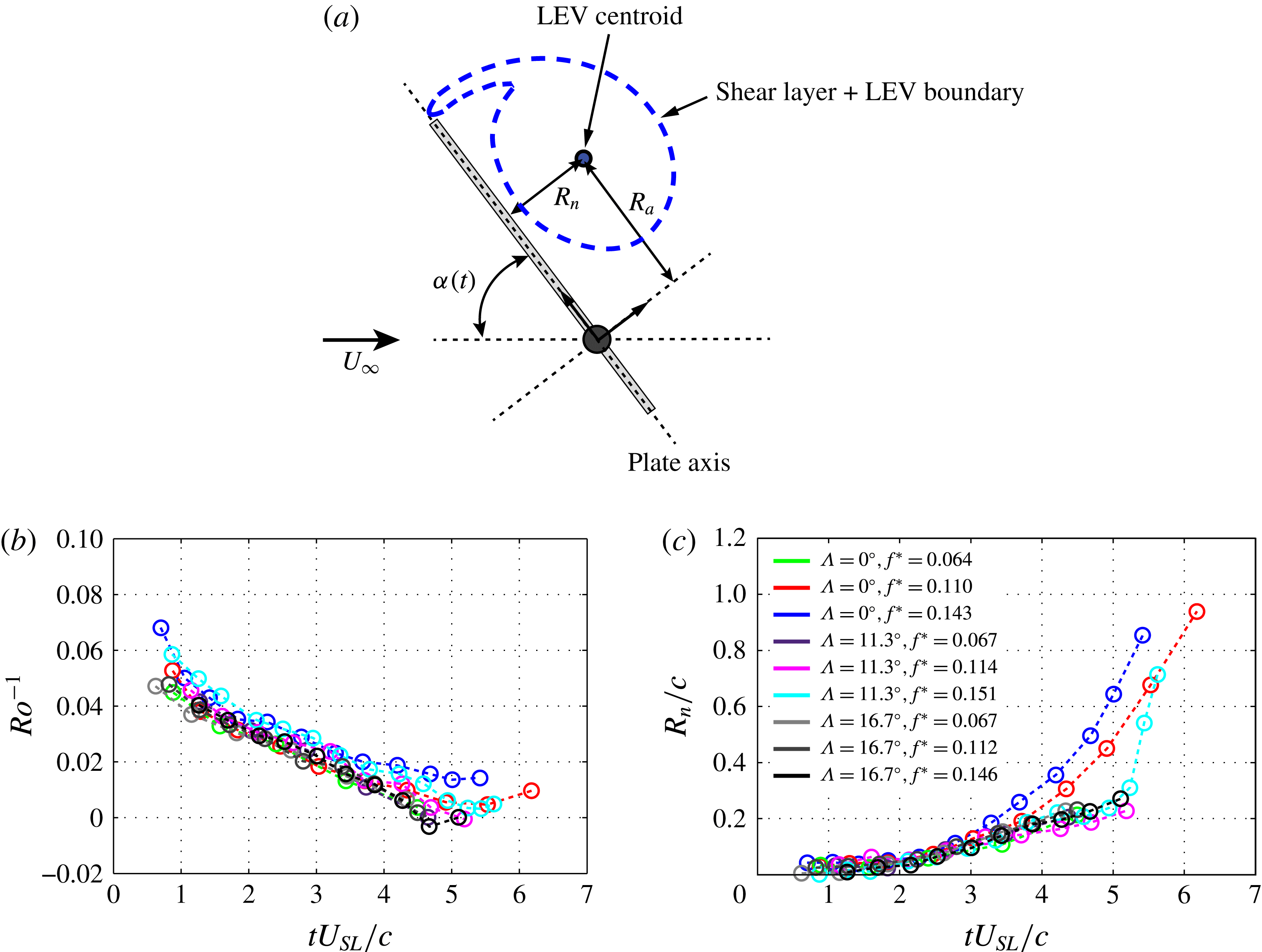
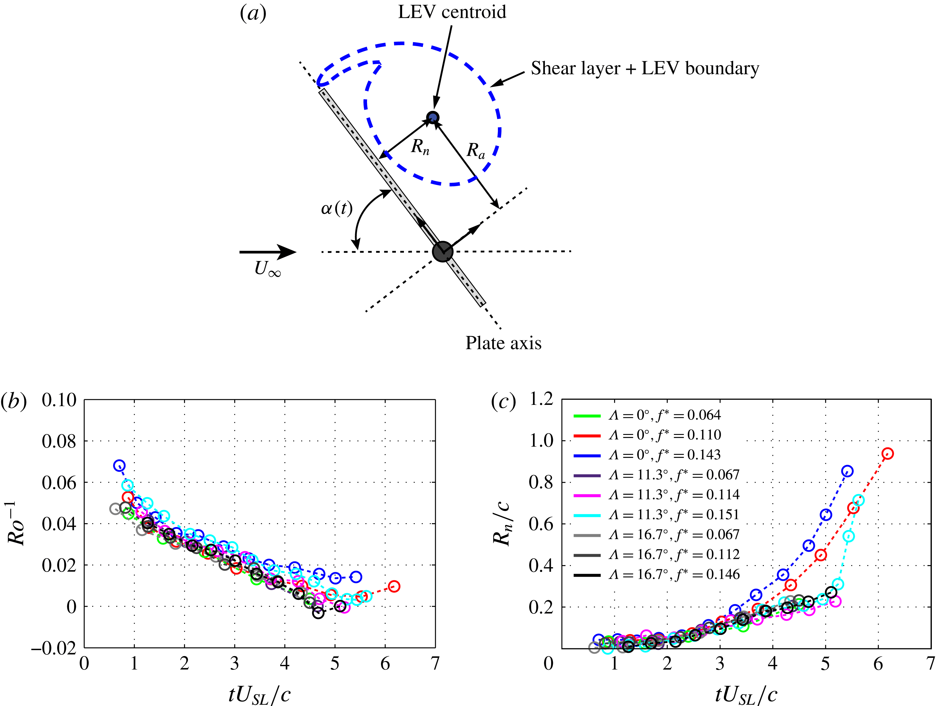
). In each case, the unsteady motion was sinusoidal with nearly constant frequency and amplitude, as discussed in Onoue et al. (Reference Onoue, Song, Strom and Breuer2015) and Onoue & Breuer (Reference Onoue and Breuer2016). The spatial location of the LEV centroid is tracked using the vortex identification technique described in § 2. As depicted in figure 5(a), the location of the vortex centroid relative to the axis of rotation is denoted as
 $R_{a}$
, and the shortest distance connecting the vortex centroid and the plate axis is designated as
 $R_{n}$
.
The Rossby number,
 $Ro$
, is used to quantify the relative importance between rotational accelerations and the axial movement of the LEV core during the vortex formation process. Following Onoue & Breuer (Reference Onoue and Breuer2016), the Rossby number is defined as
 $Ro=U_{SL}/R_{a}f\unicode[STIX]{x0394}\unicode[STIX]{x1D6FC}$
, where
 $U_{SL}$
denotes the characteristic velocity of the leading-edge feeding shear layer. In this study, the definition of
 $U_{SL}$
is generalised so as to account for the variations in pitching frequency, amplitude, pivot location and leading-edge sweep angle:
 $$\begin{eqnarray}U_{SL}=4f\unicode[STIX]{x0394}\unicode[STIX]{x1D6FC}(c_{eff}-(c-x_{p}))+U_{eff}\sin (\unicode[STIX]{x1D6FC}(t)),\end{eqnarray}$$
where
 $c_{eff}$
is the effective wing chord measured at the spanwise location corresponding to the central PIV plane, and
 $U_{eff}$
is the effective free-stream velocity defined as
 $U_{eff}=U_{\infty }\cos (\unicode[STIX]{x1D6EC})$
. Note that for a rectangular planform (
 $\unicode[STIX]{x1D6EC}=0^{\circ }$
),
 $c_{eff}=c$
and
 $U_{eff}=U_{\infty }$
. Our formulation of the feeding shear-layer velocity can be interpreted as the vector sum of the local velocity of the leading edge and the component of the free stream in the direction of the plate excursion. As discussed in Onoue & Breuer (Reference Onoue and Breuer2016), this formulation ensures that the shear-layer velocity is approximately aligned with the orientation of the shear layer at the leading edge. In figure 5(b), the inverse of the Rossby number is plotted as a function of the dimensionless time, where time is normalised by
 $U_{SL}$
and
 $c$
. All nine cases collapse very well over a range of reduced frequencies. This suggests that the proposed scaling of the vortex axial position captures the essential physics associated with the present problem. As can be inferred from the small values of
 $Ro^{-1}$
in figure 5(b), the important force that contributes to the LEV stability is the centrifugal force. This is consistent with the present observation in that the LEVs associated with high reduced frequencies (hence large centrifugal acceleration) exhibit less tendency to drift towards the pitch axis. The evolution of the normal distance,
 $R_{n}$
, as a function of the dimensionless time is shown in figure 5(c). All cases collapse onto the same curve until approximately
 $tU_{SL}/c$
 ${\approx}$
3.8, then subsequently bifurcate into two distinct branches. The curves corresponding to the rectangular planform (e.g. red and blue) start to increase precipitously upon crossing this bifurcation point as the vortex lifts off from the plate. In contrast, the curves associated with the swept planforms (e.g. cyan and magenta) extend to a later time of
 $tU_{SL}/c\approx 5.2$
, reflecting the fact that the dimensionless vortex residence time is increased by nearly 30 % relative to the rectangular planform (figure 4). At low reduced frequencies, the integrity of the LEVs begins to diminish prior to separation, owing to excessive entrainment of the secondary vorticity.
(a) Definition sketch illustrating the spatial location of the LEV centroid with respect to the pitching plate, where
 $R_{a}$
denotes the axial distance between the LEV centroid and the pivot point, and
 $R_{n}$
represents the shortest distance between the LEV centroid and the plate axis. The temporal evolution of: (b) the inverse Rossby number,
 $Ro^{-1}$
, and (c)
 $R_{n}/c$
, where time is normalised by the feeding shear-layer velocity,
 $U_{SL}$
.
It is documented in the archival literature that the separation of a leading-edge vortex from an unsteady wing is governed by the arrival of the LEV core at the trailing edge. Rival et al. (Reference Rival, Kriegseis, Schaub, Widmann and Tropea2014) demonstrated that the occurrence of LEV separation roughly coincides with the instant at which the rear stagnation point of the LEV coalesces with the trailing-edge stagnation point, which in turn promotes the development of a trailing-edge vortex and subsequent induction of a strong reverse flow between the two counter-rotating vortices (i.e. LEV and trailing-edge vortex) that ultimately tear them apart. Based on this observation, the authors suggested that the primary characteristic length scale governing the vortex separation is one wing chord. Then it naturally follows that the vortex detachment can be delayed by increasing the reduced frequency (and thus the centrifugal force), which in turn helps mitigate the axial drifting of the vortex core towards the trailing edge, as discussed earlier. However, it is important to note that the previous explanation for the LEV separation is established under the premise that the LEV core approaches sufficiently close to the trailing edge, which, in some cases, may be entirely irrelevant. For example, the data in figure 4(a) illustrate a case in which the LEV separates from the plate when the vortex core is nowhere near the trailing edge. Given this observation, another mechanism must be responsible for the separation of the LEV on a pitching (rectangular) planform operating at a high reduced frequency. A further discussion on this will be provide in § 3.4, where we will demonstrate that the vortex separation is influenced by the energetics of the vortex core.
3.2 Vorticity dynamics
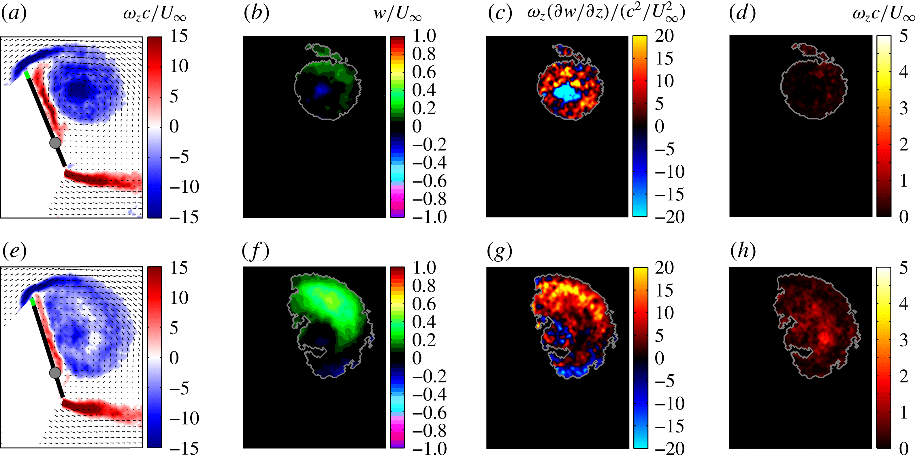
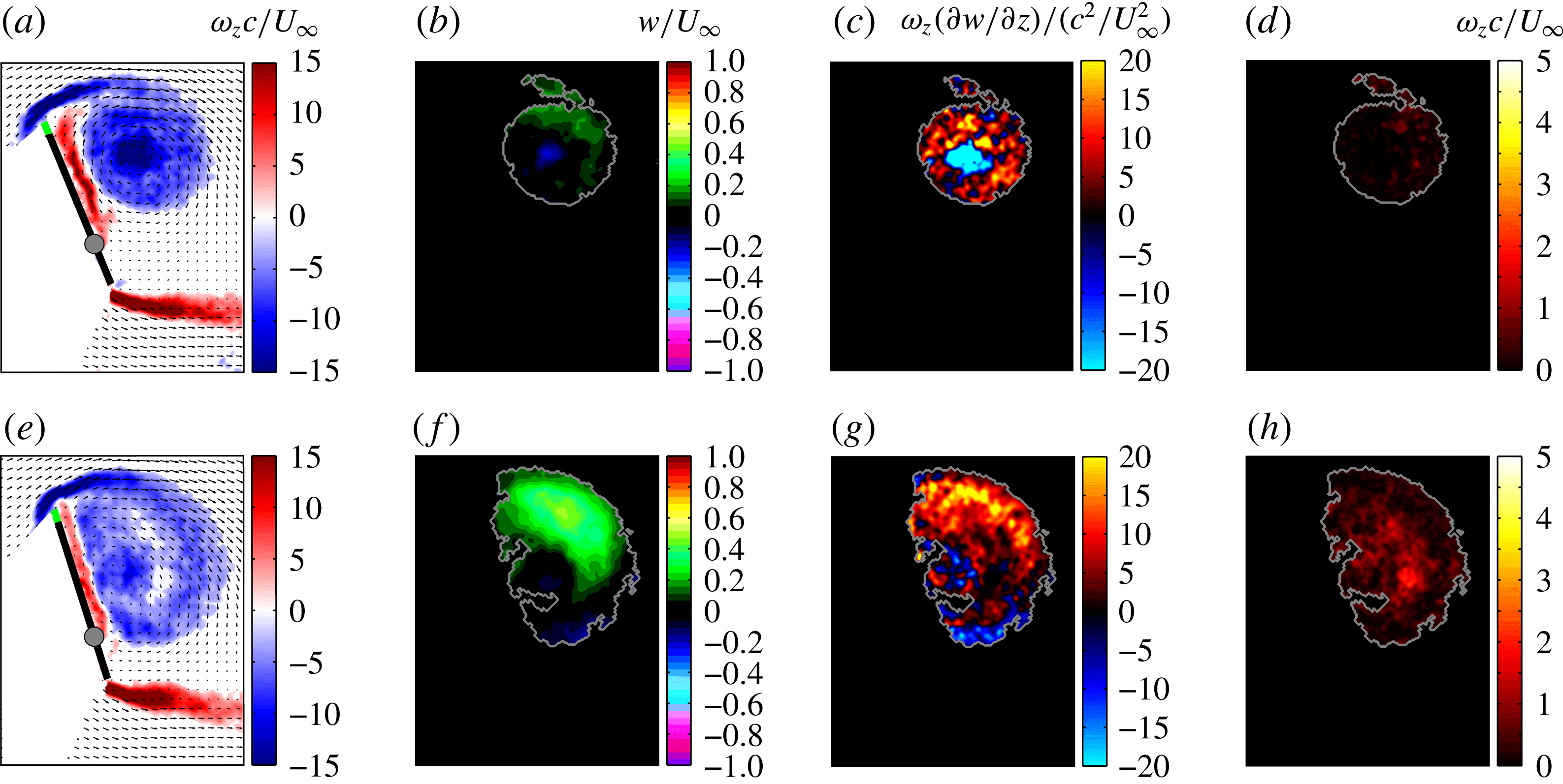
We continue the discussion by taking a closer look into the vorticity dynamics of a strong and well-defined LEV associated with the nominally two-dimensional rectangular wing. As illustrated in figure 6(c), the effect of vortex stretching is most prominent in the vicinity of the LEV centroid (i.e.
 $\unicode[STIX]{x1D714}_{z}(\unicode[STIX]{x2202}w/\unicode[STIX]{x2202}z)(c^{2}/U_{\infty }^{2})\ll 0$
), which exactly coincides with the material region marked by a high concentration of strong vorticity (figure 6
a). The current result suggests that the tightening of a vortex core with increasing reduced frequency, as has been previously observed by Granlund, Ol & Bernal (Reference Granlund, Ol and Bernal2013) and Onoue & Breuer (Reference Onoue and Breuer2016), is a manifestation of vortex stretching, which results in the amplification of the vorticity magnitude and the commensurate reduction in the cross-sectional area of the vortex filament. On the other hand, it is interesting to note that the outer region of the vortex core is predominantly subject to vortex compression. We also note that the level of vortex stretching/compression is approximately uniform within the measurement volume. While the magnitude of the spanwise flow inside the LEV is relatively minor (figure 6
b), the fact that the vortex core is subject to vortex stretching and compression (figure 6
c) clearly indicates that the interior flow is inherently three-dimensional (i.e.
 $\unicode[STIX]{x1D714}_{z}(\unicode[STIX]{x2202}w/\unicode[STIX]{x2202}z)$
is not negligible), even at the spanwise location close to the symmetry plane. The present observation is not only striking, but has a significant implication because it challenges a commonly held view – as discussed, for example, by Jardin et al. (Reference Jardin, Farcy and David2012), Granlund et al. (Reference Granlund, Ol and Bernal2013) and Kriegseis et al. (Reference Kriegseis, Kinzel and Rival2013), who examined the LEV dynamics of unsteady rectangular planforms with free-end conditions – that the three-dimensionality of the LEV is localised to the near-tip region encompassing approximately one wing chord in-board of the tip, and that the flow over the central portion of the wing is predominantly two-dimensional (across a range of reduced frequencies and aspect ratios varying from 2 to 6). Such generalisation was made based on the fact that various planar (2D) quantities (e.g. LEV circulation, vortex size and centroid location) remain relatively uniform across the central compartment of the wing. Even in our configuration, a slab of LEV close to the mid-span section was found to be topologically homogeneous three-dimensional flow, where the spanwise variations in vortex circulation, cross-sectional area and centroid location are very small, but the interior flow of the vortex core is subject to a uniform vortex stretching/compression. In the recent numerical investigation of Visbal & Garmann (Reference Visbal and Garmann2017), the authors demonstrated that the presence of a small gap (i.e. 1 %–2 % of the chord length) between the stationary wall and the pitching wing – which allows for the formation of a tip vortex – can strongly alter the global topology of an LEV. This is an important result because it questions the validity of the general assumption that nominally two-dimensional flow conditions can be realised in experiments by minimising the profile-tip spacing at the walls to
 $0.02c$
or less (see, e.g. Slaouti & Gerrard Reference Slaouti and Gerrard1981; Lisoski Reference Lisoski1993; Ringuette, Milano & Gharib Reference Ringuette, Milano and Gharib2007; Ol et al.
Reference Ol, Bernal, Kang and Shyy2009; Rival, Prangemeier & Tropea Reference Rival, Prangemeier and Tropea2009). In addition, the flow configuration considered by Kim et al. (Reference Kim, Strom, Mandre and Breuer2017) is comparable to the current wind tunnel installation, wherein the gap distance between the tip of the wing and the test section wall represented 60 % of the chord length. The authors demonstrated that the temporal evolution of the LEV circulation and other salient 2D vortex characteristics associated with an
 $AR=4.5$
hydrofoil undergoing a pitching–heaving sinusoidal manoeuvre remained largely independent of the end conditions (i.e. with and without the end plates) over the central compartment of the wing. We note that this result is very much in line with the reports of Jardin et al. (Reference Jardin, Farcy and David2012) and Kriegseis et al. (Reference Kriegseis, Kinzel and Rival2013) that involved free-tip conditions, where the blockage and wall boundary layer effects are expected to have only minor influence, if any, on the formation and subsequent growth of the tip vortices. For this reason, we believe that the flow configuration of the current study is analogous to having a free-end condition. Nevertheless, it should be reiterated that the spanwise invariance of two-dimensional vortex properties does not rule out the possibility that the interior flow of the vortex core is three-dimensional. What has been often overlooked in the past is really the detailed characterisation of the three-dimensionality of the vortex core, especially near the vortex centroid where the strongest vorticity generally occurs (figure 6
a,c). To this end, the present study provides an important evidentiary support that clearly demonstrates that a seemingly two-dimensional LEV (with a reasonable degree of spanwise uniformity in circulation, vortex size, centroid location, etc) does not necessarily entail that the interior vortical flow is nominally two-dimensional and that the three-dimensional dynamics of vortex filaments (i.e. vortex stretching/compression) can significantly alter the behaviour and characteristics of the LEV.
(a–d) Rectangular planform (
 $\unicode[STIX]{x1D6EC}=0^{\circ }$
,
 $tU_{SL}/c=4.2$
) and (e–h) swept planform (
 $\unicode[STIX]{x1D6EC}=12^{\circ }$
,
 $tU_{SL}/c=4.6$
). Contours of (a,e) normalised spanwise vorticity, (b,f) out-of-plane velocity, (c,g) vortex stretching/compression and (d,h) positive vorticity accumulation are displayed. In both cases
 $f^{\ast }\approx 0.15$
.
Turning our attention to the vorticity dynamics associated with the swept planform (figure 6
e–h), we highlight several prominent features that differ conspicuously from the rectangular case. First, we note that the magnitude of the spanwise velocity induced in the LEV is approximately two to three times higher compared to the rectangular counterpart (figure 6
f). Secondly, the LEV is subject to strong spanwise compression (or radial expansion:
 $\unicode[STIX]{x1D714}_{z}\unicode[STIX]{x2202}w/\unicode[STIX]{x2202}zc^{2}/U_{\infty }^{2}\gg 0$
) as reflected by the large cross-sectional area of the LEV core (figure 6
g). Here, no evidence of significant vortex stretching is observed in the vortex core, which may be due to strong spanwise flow (figure 6
f) and significant entrainment of the secondary vorticity emanating from the plate surface (figure 6
h), where the latter presumably gives rise to a conspicuous region of weak or no vorticity near the vortex centroid (figure 6
e). This is in contrast to the rectangular case, where the flux of surface vorticity is minimal, particularly at high reduced frequencies (figure 6
d). Our results are in line with that of Hartloper & Rival (Reference Hartloper and Rival2013), in which the authors reported that the LEVs on rectangular, lunate and truncate planforms undergoing a sinusoidal pitch-up manoeuvre are subject to vortex compression, where the truncate planform has the curvature only along the leading edge, while the lunate counterpart has the same curvature along both the leading and trailing edges. It is worthwhile mentioning that the results of Hartloper & Rival (Reference Hartloper and Rival2013) suggest that the tip effects on the lunate and truncate planforms are less pronounced than the rectangular counterpart, as indicated by lower levels of vorticity tilting and in-board directed spanwise flow, which can be attributed to smaller tip vortices associated with these planforms. In contrast to the rectangular case, where the LEV deformed into an arch-shaped vortex (found previously by e.g. Yilmaz & Rockwell Reference Yilmaz and Rockwell2012), LEVs associated with the swept planforms remained nearly parallel to the plate surface, revealing a higher level of stability and spanwise uniformity during the vortex growth phase (Hartloper & Rival Reference Hartloper and Rival2013, figures 8 and 10). We note that our current results and those of Hartloper & Rival (Reference Hartloper and Rival2013) suggest that the sweptback leading edge plays an important role in prolonging the vortex residence time. It is also interesting to note that the physical length of the deformed vortex tube associated with the rectangular planform (as illustrated in Hartloper & Rival Reference Hartloper and Rival2013, figure 8) is notably longer than those of the swept planforms. This observation may suggest that the formation of an arch-shaped vortex is driven, in part, by the process of vortex stretching; therefore, the apparent early LEV separation associated with the rectangular planform (figure 4; Hartloper & Rival Reference Hartloper and Rival2013, figure 8) may be a manifestation of vortex stretching, where the concomitant elongation of the vortex filaments inevitably induces an abrupt displacement of the central portion of the LEV from the wing surface, owing to the physical constraints on the kinematics of the vortex filaments (i.e. Helmholtz’s vortex laws) that necessitate the LEV to be pinned down to the ends of the wing by the tip vortices (Beem et al.
Reference Beem, Rival and Triantafyllou2012; Hartloper & Rival Reference Hartloper and Rival2013; Visbal & Garmann Reference Visbal and Garmann2017).
Several researchers have pointed out that the occurrence of LEV pinch-off is dictated in part by the intrusion of the ejection shear layer from the wing surface that severs the leading-edge feeding shear layer from the vortex core (see, e.g. Rival et al. Reference Rival, Kriegseis, Schaub, Widmann and Tropea2014; Akkala, Eslam Panah & Buchholz Reference Akkala, Eslam Panah and Buchholz2015). While this is a salient phenomenon commonly associated with the plunging wing experiments, we believe that the intrusion of the surface shear layer is not a prominent mechanism governing the separation of the LEV in the case of purely pitching wings. In our series of pitching experiments, including those reported in Onoue & Breuer (Reference Onoue and Breuer2016), we have not seen a case where the surface vorticity cuts off the feeding shear layer. In most cases, some of the secondary vorticity becomes entrained into the LEV core via self-induction. This discrepancy between pitching versus plunging wings may be due to differences in the effective angle of attack, where a smaller effective angle of attack generally associated with the plunging wing experiments presumably leads to a more violent interaction between the feeding and the surface shear layers. As can been seen, for example, in figure 4 of the current manuscript, the angle that the leading-edge feeding shear layer makes with the pitching plate is very large (often exceeding 90 degrees at large angles of attack), making it difficult for the surface vorticity to pierce the feeding shear layer. This being said, the causality between the intrusion of the surface vorticity and the separation of the LEV remains somewhat elusive. According to Rival et al. (Reference Rival, Kriegseis, Schaub, Widmann and Tropea2014), the intrusion occurs upon the arrival of the LEV core at the trailing-edge stagnation point, but the results of Akkala et al. (Reference Akkala, Eslam Panah and Buchholz2015), see, e.g. figures 7(e) and 12(c), suggest that this is not necessarily the case. We believe further studies are necessary to bring closure to this problem and to establish a more definitive causal relation between the intrusion of the surface vorticity layer and the severing of the feeding sheet, and hence the vortex pinch-off.
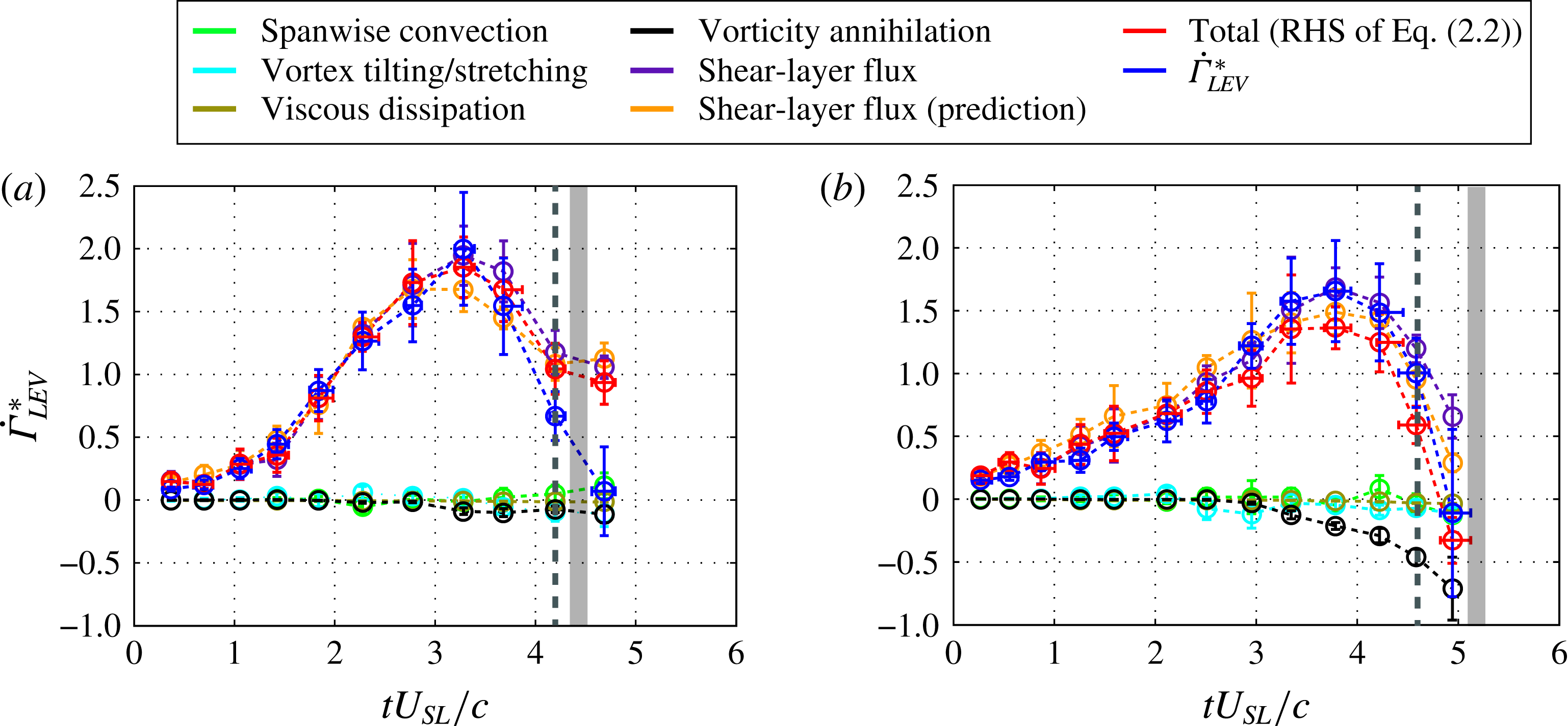
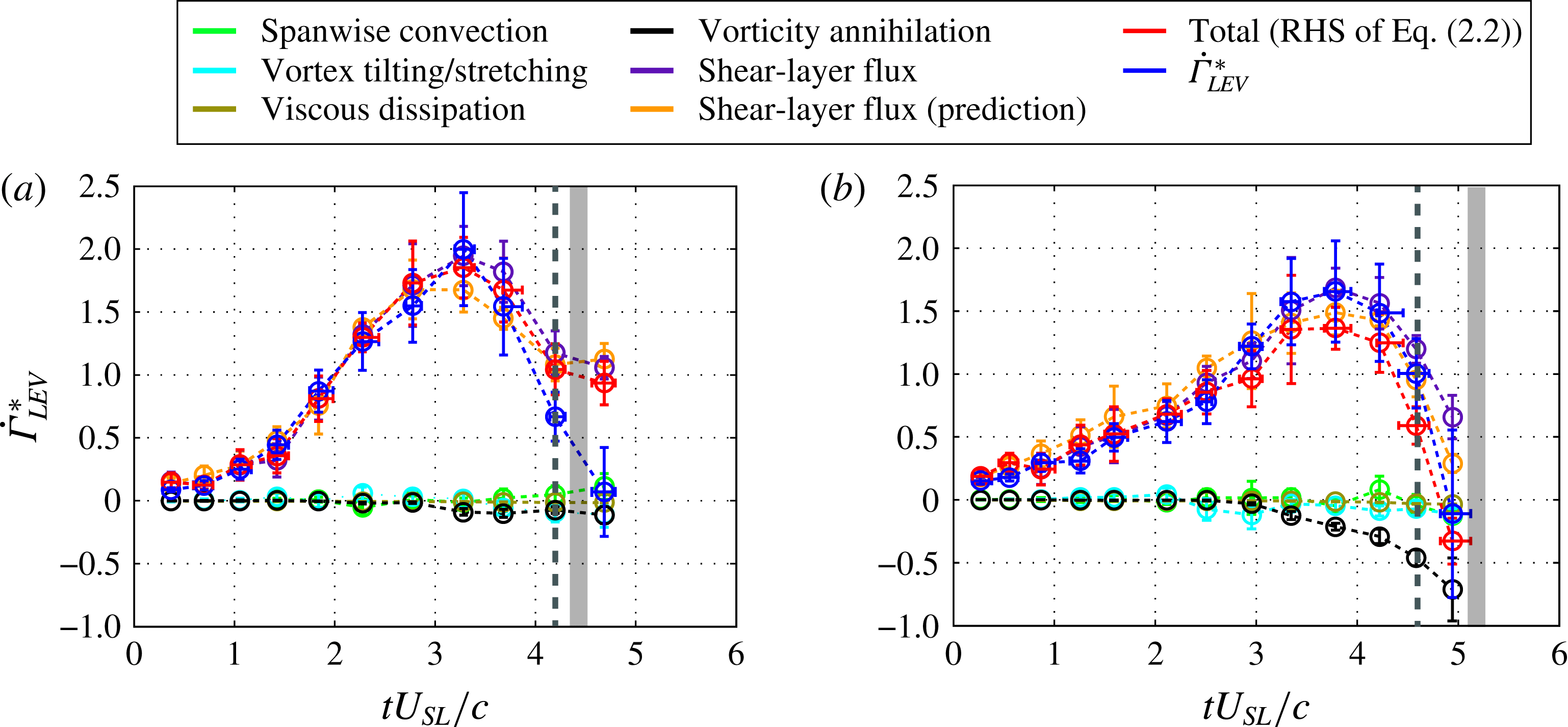
The temporal evolution of the LEV circulation budget associated with: (a) rectangular planform and (b) swept planform (
 $\unicode[STIX]{x1D6EC}=11.3^{\circ }$
) at
 $f^{\ast }\approx 0.15$
. The rate of change of LEV circulation and time are, respectively, normalised by
 $U_{\infty }^{2}$
and
 $U_{SL}/c$
. The shaded grey bar designates the approximate time of vortex separation, while the dashed grey line designates the time corresponding to figure 6. Negative values imply circulation loss.
3.3 LEV circulation budget
The formulation derived in § 2.3 is employed to analyse the relative importance of the vorticity transport mechanisms occurring inside the LEV core to the vortex development. Here, we consider two cases (
 $\unicode[STIX]{x1D6EC}=0^{\circ }$
and
 $11.3^{\circ }$
) with the same reduced frequency (
 $f^{\ast }=0.15$
). In figure 7, the dimensionless rate of change of LEV circulation is plotted as a function of dimensionless time. The uncertainty associated with each term in (2.2) is evaluated using an error propagation formula derived through a Taylor expansion. First, we note that the left-hand side of (2.2) agrees well with the right-hand side, verifying the accuracy of the present formulation. As expected, the growth of LEV circulation is primarily dictated by the flux of vorticity transported into the vortex core through the leading-edge feeding shear layer. As shown in figure 7, the shear-layer flux is slightly lower on the swept planform, which can be attributed, in part, to approximately 5 % lower mean feeding shear-layer velocity (verified experimentally); one can also verify that our model for
 $U_{SL}$
(3.1) predicts that, on average, the feeding shear-layer velocity for the swept case is 4.5 % lower than the rectangular counterpart. The validity of our formulation of
 $U_{SL}$
is verified by the fact that the magnitude of the shear-layer flux can be reasonably estimated by substituting
 $U_{SL}$
for
 $u_{\unicode[STIX]{x1D709}}$
in (2.2), as shown in figure 7. Circulation loss due to viscous dissipation was found to be negligible throughout the vortex formation phase. This is presumably because the time scale associated with LEV formation is several orders of magnitude smaller than that of vortex diffusion. In addition, the spanwise convective term had no measurable effect on the LEV circulation budget, despite the fact that the magnitude of spanwise flow induced in the vortex core can exceed 50 % of the free-stream velocity (figure 6
f). It should be noted that in order to regulate the growth of LEV circulation through spanwise convection, the out-of-plane velocity,
 $w$
, must couple to a vorticity gradient,
 $\unicode[STIX]{x2202}\unicode[STIX]{x1D714}_{z}/\unicode[STIX]{x2202}z$
, as entailed by (2.2). Provided that the present analysis is restricted to the small section of the wing, where the LEV core is largely uniform in size, shape and intensity, the magnitude of
 $\unicode[STIX]{x2202}\unicode[STIX]{x1D714}_{z}/\unicode[STIX]{x2202}z$
happens to be very small; the present assertion is also reinforced by fact that the spanwise variation in the magnitude of LEV circulation was found to be less than 0.5 % within the measurement volume. For this reason, it is concluded that the spanwise vorticity transport does not play a significant role in regulating the LEV growth, at least for the present flow configuration. However, the interior flow of this particular LEV is undeniably three-dimensional, as evident by the high level of vortex compression (figure 6
g). It should be noted that an LEV can still be approximated as two-dimensional – even in the case where the spanwise velocity through the interior of the vortex represents a high percentage of the free-stream velocity – as long as the spatial (
 $x,y,z$
) gradients of spanwise velocity are small, relative to the magnitudes of the corresponding components of the vorticity vector, such that the term
 $(\unicode[STIX]{x1D74E}\boldsymbol{\cdot }\unicode[STIX]{x1D735})\boldsymbol{u}$
on the right-hand side of (2.1) (or (2.2)) can be neglected; in essence this implies that, while the presence of spanwise flow is a necessary condition for an LEV to be three-dimensional, it is not a sufficient one. Furthermore, the integral values of the vortex tilting/stretching term remain very small throughout the vortex formation phase. This result resonates well with the fact that the circulation of a vortex line must be unaffected by vortex tilting and/or stretching in accordance with Helmholtz’s second theorem (e.g. Kundu & Cohen Reference Kundu and Cohen2008); the invariance of vortex circulation under the action of vortex tilting has been previously verified by Wojcik & Buchholz (Reference Wojcik and Buchholz2014) and Eslam Panah et al. (Reference Eslam Panah, Akkala and Buchholz2015). The effect of vorticity annihilation becomes pronounced during the later phase of the vortex development process, in particular on the swept planforms. As shown in figure 7(b), the magnitude of the annihilation term starts to increase monotonically at approximately
 $tU_{SL}/c$
 ${\approx}$
3, and nearly offsets the shear-layer flux by
 $tU_{SL}/c$
 ${\approx}$
5; this trend is generally associated with the process of vortex breakdown. A similar behaviour has been observed by Wojcik & Buchholz (Reference Wojcik and Buchholz2014) on a revolving rectangular planform at Reynolds numbers of
 $O(10^{3})$
, where the occurrence of vortex breakdown was shown to be strongly correlated with a high level of vorticity annihilation. The authors concluded that vorticity annihilation is often a dominant mechanism in regulating the LEV circulation growth, more so than the spanwise convective transport of vorticity. This is not to say, however, that the role of spanwise convection is insignificant. At some phases of the wing excursion, it was demonstrated that the spanwise convection plays an important role by nearly equalising the flux of vorticity pumped into the vortex core via the feeding shear layer. The authors also made an interesting observation by noting that the spanwise vorticity transport becomes more pronounced as the Reynolds number is increased (note that the Reynolds number here is defined based on the wing tip velocity at the mid-span). This may be explained by the fact that the concomitant increase in the centrifugal forces results in larger spanwise pressure gradients, which in turn promotes spanwise transport of vorticity inside the vortex core (see, e.g. Lentink & Dickinson Reference Lentink and Dickinson2009); note that the centrifugal force,
 $F_{c}$
, scales as
 $F_{c}\sim \unicode[STIX]{x1D6FA}^{2}r$
, where
 $\unicode[STIX]{x1D6FA}$
represents the angular velocity of the wing and
 $r$
is the rotational radius. It is important to bear in mind that, in the case of a revolving planform, the centrifugal force acts approximately parallel to the axis of the vortex tube such that it contributes to the generation of spanwise pressure gradients, but this is not the case for a pitching wing since the centrifugal force acts approximately normal to the vortex axis. Finally, we note that the plots in figure 7(a,b) are truncated at
 $tU_{SL}/c$
 ${\approx}$
4.7 and 5, respectively, because after this time some portion of the LEV core escapes the measurement domain, and grey vertical lines designate approximate vortex separation times.
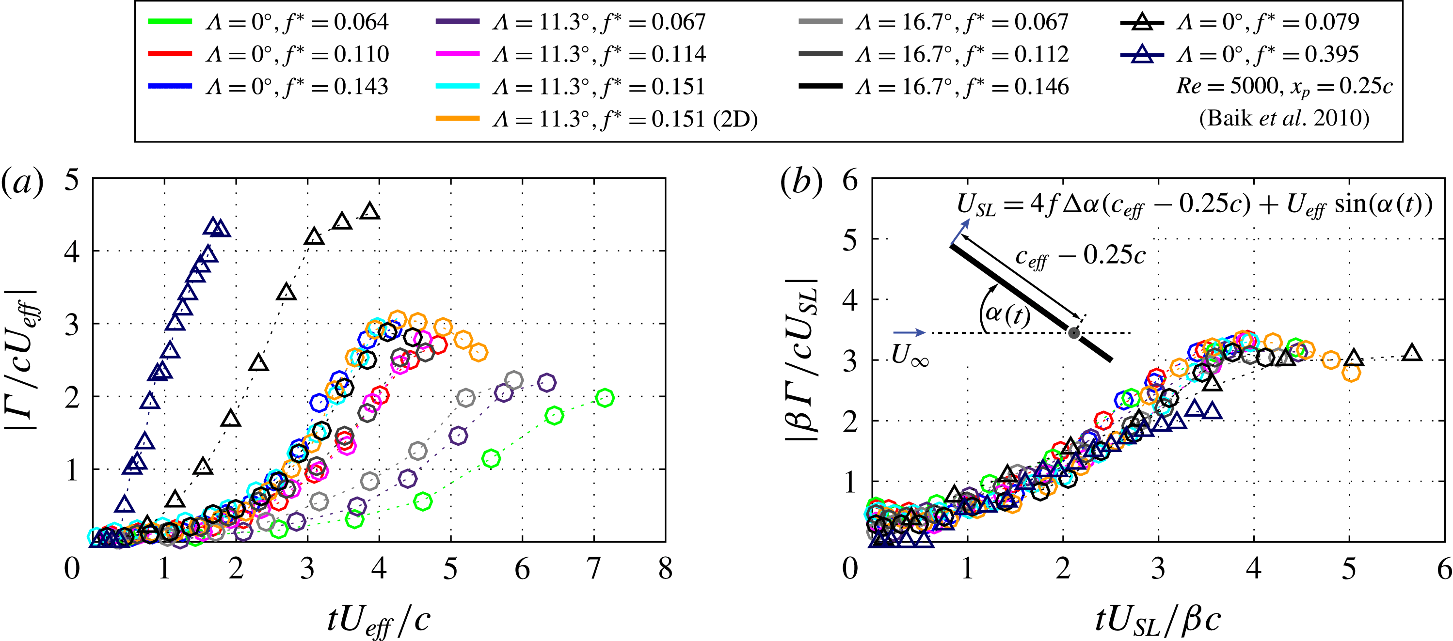
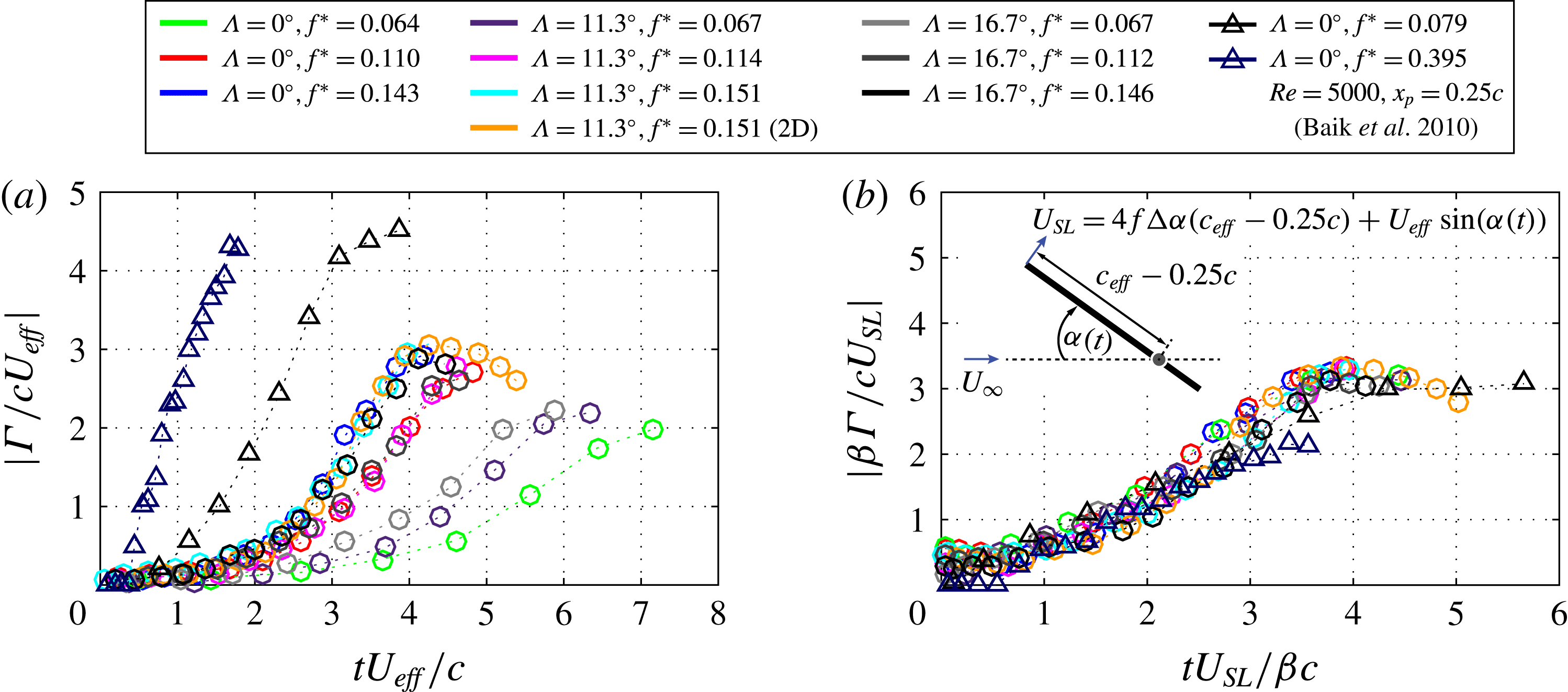
Various LEV circulation time histories normalised by: (a) the effective free-stream velocity,
 $U_{\mathit{eff}}$
, and maximum chord,
 $c$
and (b) the feeding shear-layer velocity,
 $U_{SL}$
and maximum chord,
 $c$
. The constant coefficient
 $\unicode[STIX]{x1D6FD}$
depends on the physical configuration of the vortex generator, i.e. the location of the pivot axis.
3.4 A scaling relationship for LEV formation time and circulation
In order to determine a scaling law for the LEV formation time and circulation that incorporates the effects of pitch rate and leading-edge sweep angle, we evaluate the spanwise circulation of the LEVs associated with three different planforms over a range of reduced frequencies (
 $f^{\ast }=0.064{-}0.151$
), while keeping the maximum pitching amplitude and the Reynolds number fixed at approximately
 $80^{\circ }$
and
 $1.03\times 10^{5}$
, respectively. Various LEV circulation time histories are shown in figure 8(a), where circulation and time are normalised using the effective free-stream velocity,
 $U_{\mathit{eff}}$
, and maximum chord,
 $c$
. Here
 $t=0$
corresponds to an instant when the plate crosses the equilibrium angle of attack,
 $\unicode[STIX]{x1D6FC}=0^{\circ }$
, and the circulation is evaluated at subsequent times as long as the entire vortex boundary remained within the field of view. In each case, the LEV circulation increases monotonically with time as the plate rotates to large angles of incidence. The LEV associated with the rectangular planform achieves a maximum circulation approximately when the vortex separates from the plate; Onoue & Breuer (Reference Onoue and Breuer2016) demonstrated that the circulation of the LEVs shed from the rectangular plate remains nearly constant as the vortex core propagates downstream. In contrast, the circulation curve associated with the swept planform may undergo a gradual decrease during the vortex formation process (see, e.g. figure 8:
 $\unicode[STIX]{x1D6EC}=11.3^{\circ }$
,
 $f^{\ast }=0.15$
) if the flux of secondary vorticity exceeds that of the feeding shear layer as discussed in the previous section; note that the case
 $\unicode[STIX]{x1D6EC}=11.3^{\circ }$
,
 $f^{\ast }=0.15$
is repeated using the 2D PIV setup to obtain a larger field of view so that the LEV circulation can be measured for an extended period of time. Moreover, the attainment of maximum circulation and vortex pinch-off do not necessarily coincide since the latter is dictated, in part, by the arrival time of the LEV at the trailing edge, as can be inferred from figure 4(b). A scaling based solely on
 $U_{\mathit{eff}}$
and
 $c$
is insufficient to characterise the LEV development across a myriad of flow conditions, as evident by the large scatter in the measured LEV circulation and vortex formation time.
Onoue & Breuer (Reference Onoue and Breuer2016) demonstrated the efficacy of scaling the LEV formation time and circulation by the feeding shear-layer velocity, and established a clear linkage between this scaling law and the concept of optimal vortex formation number (Gharib et al.
Reference Gharib, Rambod and Shariff1998; Dabiri Reference Dabiri2009). Here, we generalise the same scaling principle to not only accommodate the effect of pitch rate, but also the leading-edge sweep angle and the location of the pivot point. Recall that the shear-layer velocity is given by
 $U_{SL}=4f\unicode[STIX]{x0394}\unicode[STIX]{x1D6FC}(c_{eff}-0.25c)+U_{eff}\sin (\unicode[STIX]{x1D6FC}(t))$
, where
 $U_{eff}$
is defined as
 $U_{\infty }\cos (\unicode[STIX]{x1D6EC})$
. In the present study, we scale LEV circulation as:
 $\unicode[STIX]{x1D6FD}\unicode[STIX]{x1D6E4}/cU_{SL}$
, where
 $\unicode[STIX]{x1D6FD}$
is defined as
 $1+\unicode[STIX]{x0394}x_{p}/c$
, and
 $\unicode[STIX]{x0394}x_{p}$
denotes the relative distance between the pivot point and the mid-chord location (i.e.
 $\unicode[STIX]{x0394}x_{p}=x_{p}-c/2$
); for the present configuration (
 $x_{p}=3c/4$
),
 $\unicode[STIX]{x1D6FD}=1.25$
. It should be noted that this formulation is analogous to the dimensionless vortex formation number
 $\hat{T}$
defined by Dabiri (Reference Dabiri2009), and the constant
 $\unicode[STIX]{x1D6FD}$
serves a similar role as the constant factor
 $C$
that appears in the definition of
 $\hat{T}$
, which depends on the physical configuration of the vortex generator. The dimensionless time is scaled by
 $1/\unicode[STIX]{x1D6FD}$
to account for the fact that the onset of LEV formation is either advanced or delayed as the pivot point is taken forward or aft of the mid-chord point, respectively (Granlund et al.
Reference Granlund, Ol and Bernal2013); the sensitivity of vortex formation time and circulation to the location of pivot point can be ascribed to the changes in vorticity distribution on the pressure side of the wing during the initial phase of the pitch-up manoeuvre (Yu & Bernal Reference Yu and Bernal2013; Granlund et al.
Reference Granlund, Ol and Bernal2013). Even though the flow under consideration is intrinsically three-dimensional, as discussed earlier in § 3.1, the present scaling law is expected to remain valid because the growth of the LEV circulation is entirely independent of three-dimensional vorticity dynamics (i.e. vortex stretching, compression and tilting), as illustrated in figure 7. In addition, when the LEV becomes a free vortex at the point of separation, we know for a fact that the LEV must link up to the tip and trailing-edge vortices to form a closed loop and that the circulation of the resulting vortex loop must be spatially uniform along its contour so as to satisfy Helmholtz’s vortex laws. Therefore, we anticipate the critical formation number to converge to the same universal value at the time of vortex pinch-off, regardless of the spanwise location at which the LEV circulation is evaluated. Figure 8(b) evinces an excellent collapse of various circulation time traces. It is evident that in all cases, the value of max(
 $\unicode[STIX]{x1D6FD}\unicode[STIX]{x1D6E4}/cU_{SL}$
) and the corresponding dimensionless time occur within a narrow band of 3.5 to 4, conforming remarkably well with the concept of optimal vortex formation time. Moreover, it was shown in Onoue & Breuer (Reference Onoue and Breuer2016) that, for a rectangular plate configured to pitch about the mid-chord location (
 $\unicode[STIX]{x1D6FD}=1$
), the limiting dimensionless vortex formation time uniformly converges to approximately 3.5–4 over a range of reduced frequencies (0.038–0.11) and pitching amplitudes (
 $42^{\circ }$
–
 $100^{\circ }$
) at different Reynolds numbers. In addition, the data taken from Baik et al. (Reference Baik, Aono, Rausch, Bernal, Shyy and Ol2010) are plotted in figure 8 for comparison; in this study, the authors reported on the temporal evolution of the LEV circulation associated with a nominally 2D flat plate undergoing a linear pitch-up manoeuvre in water from
 $\unicode[STIX]{x1D6FC}=0^{\circ }$
to
 $90^{\circ }$
about the quarter-chord point (i.e.
 $x_{p}=c/4$
,
 $\unicode[STIX]{x1D6FD}=0.75$
) with two different values of reduced frequencies (i.e.
 $f^{\ast }\approx 0.08$
and 0.4) at a Reynolds number of 5000; the higher-frequency case represents a very aggressive pitch-up motion, where the wing’s rotational time scale,
 $1/2\unicode[STIX]{x03C0}f$
, is comparable to one-half the fluid convective time scale,
 $c/2U_{\infty }$
(i.e.
 $\unicode[STIX]{x03C0}fc/U_{\infty }=1$
). From figure 8(b), it is evident that the corresponding circulation curves collapse well with all the other cases, and that the saturation of the scaled vortex circulation occurs at the dimensionless formation time of approximately 3.5–4. This result is rather significant because not only does it demonstrate that the current scaling law remains valid at a considerably lower Reynolds number than what has been considered in the present study and Onoue & Breuer (Reference Onoue and Breuer2016), but also suggests that this scaling can be applied to a non-sinusoidal motion over an extended range of reduced frequency and that our
 $\unicode[STIX]{x1D6FD}$
parameter appropriately captures the effects of pivot point location on the evolution of LEV circulation and formation time. While the current results suggest a certain level of universality, the extent to which our scaling law remains valid should still be verified further, in particular, with respect to larger variations in leading-edge sweep angle and pivot point location.
As discussed in Gharib et al. (Reference Gharib, Rambod and Shariff1998), the existence of the universal formation number (in the context of axisymmetric vortex ring formation) is a direct manifestation of the Kelvin–Benjamin variational principle, which, in effect, predicts that the separation of the leading vortex ring occurs when the energy of the source flow delivered by the vortex generator becomes lower than the energy of the resulting vortex ring. More recently, O’Farrell & Dabiri (Reference O’Farrell and Dabiri2014) demonstrated that the limiting size and circulation of a non-circular ring vortex are spatially uniform along its contour at the time of vortex pinch-off, and that the optimal formation numbers associated with a class of non-axisymmetric vortex rings (i.e. those generated by elliptical and oval nozzles of various aspect ratios) lie within a narrow range of 3 to 4. This is an important result because it suggests that the concept of optimal formation number can indeed be extended to more complex vortical flows that involve deformed, non-circular vortex rings. Here we exploit the Kelvin–Benjamin variational principle to elucidate the linkage between the kinetic energy content of the feeding shear layer and the growth of the leading-edge vortex on a rapidly pitching plate in a uniform flow. To this end, the dimensionless vortex energy,
 $E^{\ast }$
, is defined as:
 $E^{\ast }=E/\sqrt{I\unicode[STIX]{x1D6E4}^{3}}$
(Gharib et al.
Reference Gharib, Rambod and Shariff1998), where
 $E$
,
 $I$
, and
 $\unicode[STIX]{x1D6E4}$
, respectively, denote vortex kinetic energy, impulse, and circulation. These values are directly evaluated from the velocity fields using the following integral relations:
 $E=\unicode[STIX]{x1D70C}_{f}h\int \unicode[STIX]{x1D713}\unicode[STIX]{x1D714}_{z}\,\text{d}A$
, where
 $\unicode[STIX]{x1D713}$
is the stream function (Pozrikidis Reference Pozrikidis2011),
 $I=\unicode[STIX]{x1D70C}_{f}\int \boldsymbol{x}\times \unicode[STIX]{x1D74E}\,\text{d}A$
(Batchelor Reference Batchelor2000),
 $\unicode[STIX]{x1D6E4}=\int \unicode[STIX]{x1D714}_{z}\,\text{d}A$
, and the integration is taken over the LEV boundary. Note that the fluid density,
 $\unicode[STIX]{x1D70C}_{f}$
, is taken to be unity for convenience and the expression of
 $E$
is multiplied by the wing span,
 $h$
, to keep the dimensions consistent. It should be noted that the formulation of the normalised energy,
 $E^{\ast }$
, in terms of its impulse and circulation is consistent with the requirement of the Kelvin–Benjamin variational principle in that an alternative arrangement of the vortex ring vorticity should preserve the total impulse. Furthermore, by assuming all the fluids contained in the feeding shear layer are absorbed by the LEV, one can deduce that the LEV energy approximately equals the instantaneous energy of the feeding vortex sheet at a given dimensionless vortex formation time,
 $\unicode[STIX]{x1D6FD}\unicode[STIX]{x1D6E4}/cU_{SL}$
; recall that this parameter is equivalent to the dimensionless vortex formation time
 $\hat{T}$
defined by Dabiri (Reference Dabiri2009). The validity of this assumption is supported by the fact that the growth of the LEV is primarily dictated by the strength of the feeding shear layer, as verified in § 2.3. We note that this is the same assumption as the one made in Gharib et al. (Reference Gharib, Rambod and Shariff1998) to establish the existence of the optimal formation number for steady axis-touching vortex rings based on the Kelvin–Benjamin variational principle.
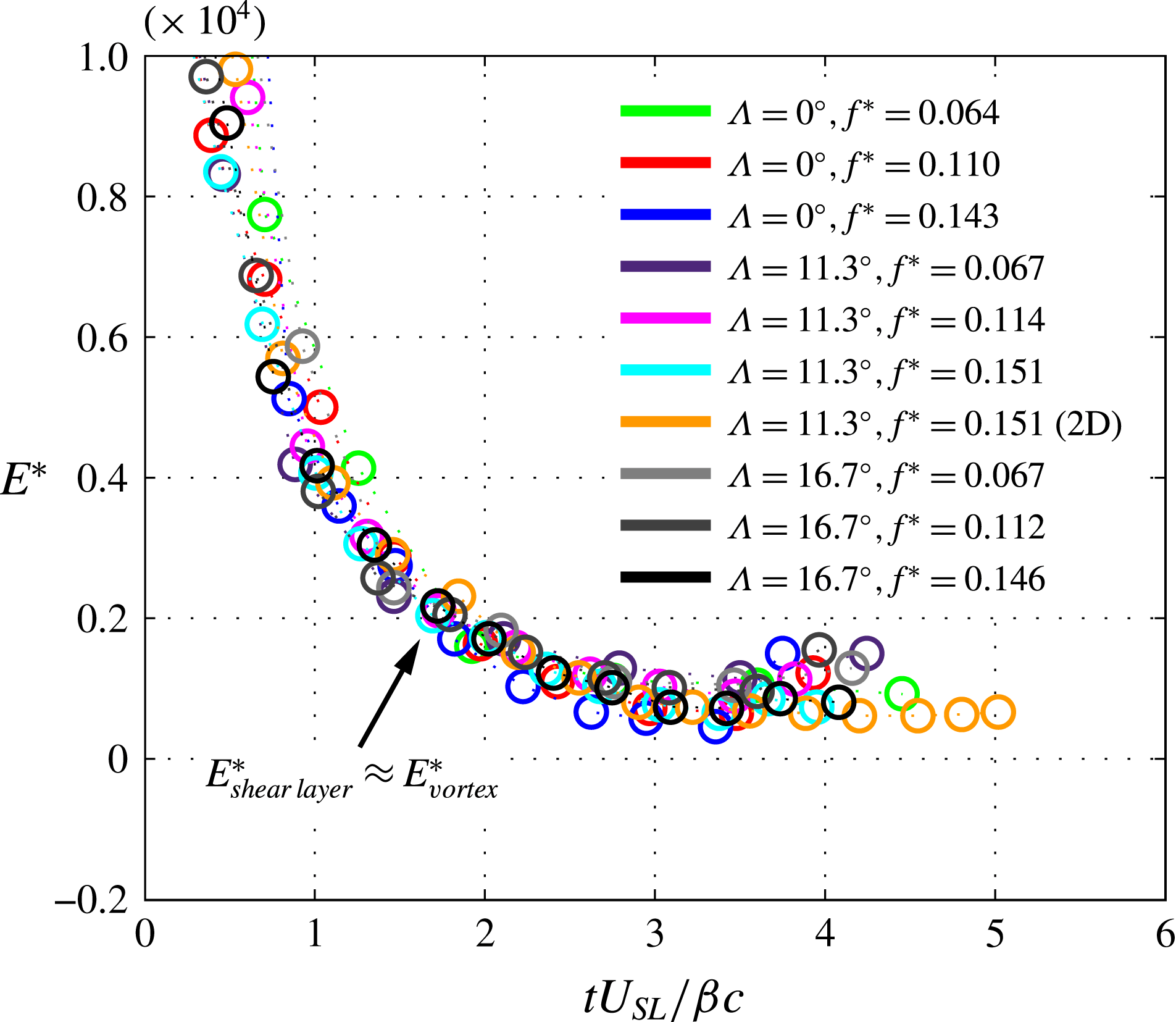
The evolution of the dimensionless vortex energy as a function of the dimensionless formation time. Based on the Kelvin–Benjamin variational principle, vortex kinetic energy is normalised by the vortex impulse and circulation. The energy of the feeding shear layer is assumed to be in balance with the energy of the resulting LEV core at any given time, i.e.
 $E_{\mathit{shear\,layer}}^{\ast }\approx E_{\mathit{vortex}}^{\ast }$
.
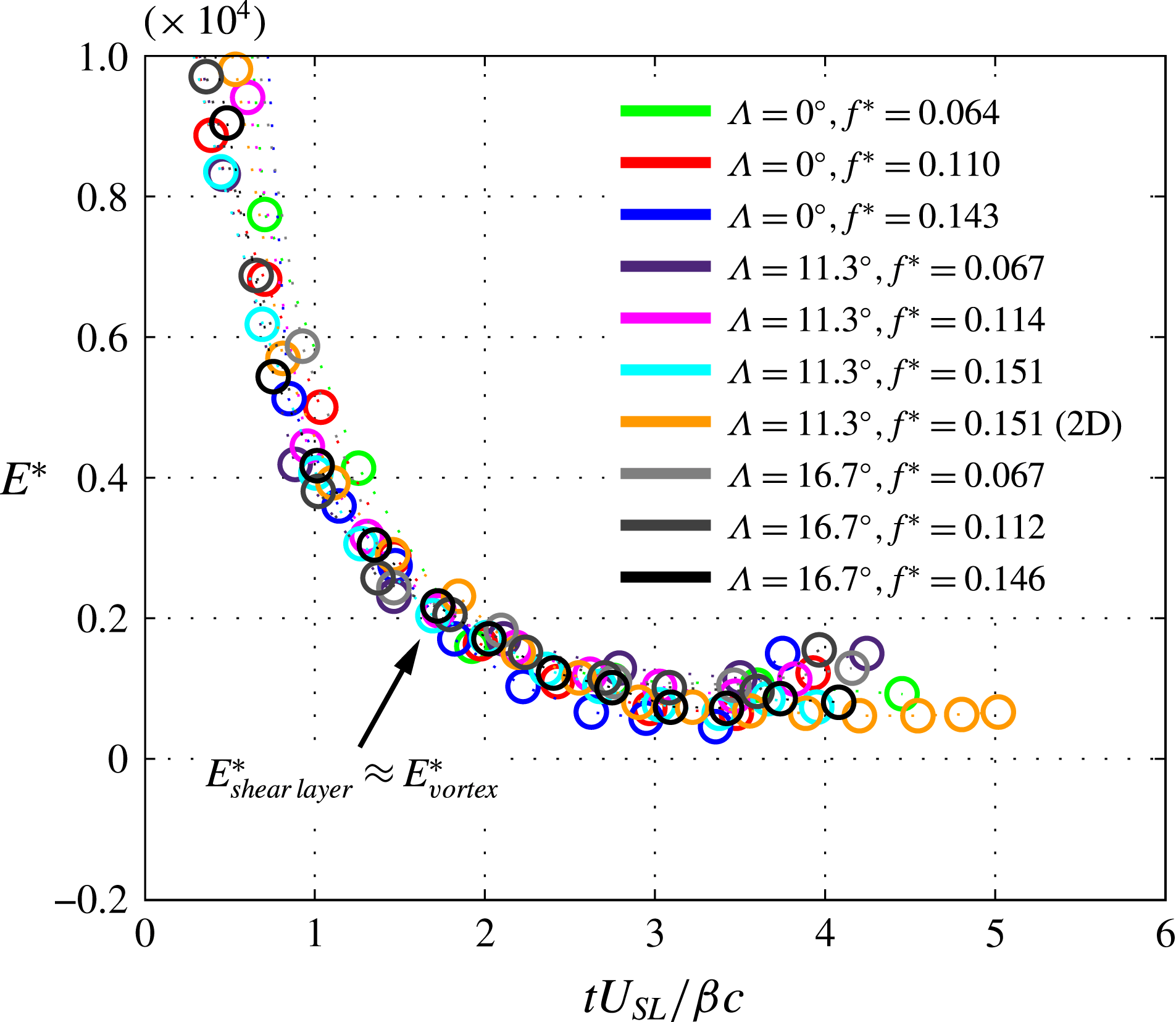
In figure 9, the dimensionless vortex energy
 $E^{\ast }$
is plotted as a function of the formation time,
 $tU_{SL}/\unicode[STIX]{x1D6FD}c$
, where it is evident that the dimensionless energy curves decrease precipitously until the limiting vortex formation time is reached at approximately 3.5–4; in the vortex ring experiment of Gharib et al. (Reference Gharib, Rambod and Shariff1998), the authors have also shown that the dimensionless energy of the vortex ring decreases monotonically with the formation number or the stroke ratio. Since the LEV cannot grow indefinitely, the dimensionless vortex energy is expected to deteriorate with increasing dimensionless vortex formation time. All the energy curves collapse very well when plotted against the dimensionless vortex formation time; an equally good collapse can be obtained by plotting
 $E^{\ast }$
as a function of
 $\unicode[STIX]{x1D6FD}\unicode[STIX]{x1D6E4}/cU_{SL}$
. This result is important as it validates the current scaling of the vortex kinetic energy with respect to its impulse and circulation. The critical dimensionless vortex energy,
 $E_{crit}^{\ast }$
, is found to reside within a moderately narrow range of 460–1100 corresponding to the limiting dimensionless vortex formation time of approximately 3.5–4 (figure 9).
To summarise,
 $E_{crit}^{\ast }$
represents the dimensionless vortex energy corresponding to the attainment of maximum vortex circulation at non-dimensional formation times between 3.5 and 4. When the value of
 $E^{\ast }$
falls below
 $E_{crit}^{\ast }$
, the kinetic energy provided by the feeding shear layer becomes too small relative to the impulse and circulation to sustain the steady growth of the LEV, and subsequently the vortex pinches off. From this argument, it follows that the vortex separation can be delayed by regulating the vortex energy and/or increasing the energy of the feeding shear layer. The same conclusion can be drawn by inspecting the dimensionless vortex formation number,
 $\unicode[STIX]{x1D6FD}\unicode[STIX]{x1D6E4}/cU_{SL}$
, where it is clear that the advancement of the formation time can be moderated by increasing the magnitude of the feeding shear-layer velocity (hence the kinetic energy of the feeding vortex sheet) and/or decreasing the circulation (i.e. energy) of the LEV. One way to reduce the vortex circulation is through the process of vorticity annihilation, as discussed earlier in § 3.3. While the influx of surface vorticity is difficult to control, it can effectively reduce the vortex circulation after the limiting formation time is reached. This is illustrated particularly well in the case
 $\unicode[STIX]{x1D6EC}=11.3^{\circ }$
,
 $f^{\ast }=0.15$
(figure 8
b), where one can see that the dimensionless circulation curve undergoes a gradual decrease after the attainment of maximum circulation at
 $tU_{SL}/\unicode[STIX]{x1D6FD}c$
 ${\approx}$
4, and beyond this time, the corresponding dimensionless energy curve remains nearly constant and even increases slightly (figure 9). Because the Kelvin–Benjamin variational principle, in effect, dictates that the vortex separation occurs at the crossover point (i.e.
 $E^{\ast }<E_{crit}^{\ast }$
) at which the energy of the shear layer feeding the vortex becomes lower than that of the resulting vortex core, it is hypothesised that the prolonged vortex attachment in the case of
 $\unicode[STIX]{x1D6EC}=11.3^{\circ }$
,
 $f^{\ast }=0.15$
(also see figure 4) can be attributed to the fact that the dimensionless vortex energy remains at a level higher than or equal to the critical vortex energy after the attainment of the critical formation time at approximately 4.
4 Concluding remarks
We characterised the LEV dynamics on a rapidly pitching plate in a uniform free stream by implementing the cyber-physical experimental setup and synchronised tomographic PIV. Through systematically modulating the reduced frequency and the angle of leading-edge sweep, we examined the behaviour of LEV formation, growth and subsequent shedding over a range of flow conditions. By quantifying the three-dimensionality of the LEV, it became apparent that the vortex core associated with the nominally two-dimensional
 $AR=5$
wing is intrinsically three-dimensional, wherein the central region of the vortex core is subject to a high level of uniform vortex stretching, even at the spanwise section near the symmetry plane. Although previous researchers have generalised that the in-board portion of the LEV (near the mid-span region) is largely two-dimensional, the findings of the current study suggest that such an assumption is an overgeneralisation. Specifically, we emphasise that the spanwise invariance of 2D vortex properties (e.g. circulation) does not ensure a nominally two-dimensional flow. While it is difficult to generalise the effects of spanwise end conditions on the resulting dynamic-stall behaviour, it would be interesting and also important to revisit some of the ‘nominally two-dimensional’ flow configurations considered by the previous investigators (e.g. Jardin et al.
Reference Jardin, Farcy and David2012; Granlund et al.
Reference Granlund, Ol and Bernal2013; Kriegseis et al.
Reference Kriegseis, Kinzel and Rival2013) to quantify the level of three-dimensionality associated with the resulting LEVs.
In the present study, we generalised the definition of the feeding shear-layer velocity,
 $U_{SL}$
, to accommodate the effects of pitching frequency, pivot location, and leading-edge sweep angle. The utility of this parameter in scaling vortex movement, formation time and circulation has been discussed. Most importantly, we demonstrated that the LEV formation time and circulation appear to follow a unified scaling principle based on the concept of optimal vortex formation number. By exploiting the generalised definitions of the dimensionless vortex circulation and formation time parameters introduced in Onoue & Breuer (Reference Onoue and Breuer2016), we demonstrated that various circulation time histories (measured across a broad range of flow conditions) can be brought into respective coincidence, where the maximum non-dimensional vortex circulation and corresponding time were shown to occur within a narrow range of 3.5 to 4. This result resonates remarkably well with the concept of formation number originally established in the work of Gharib et al. (Reference Gharib, Rambod and Shariff1998), and further supports the postulation of Dabiri (Reference Dabiri2009), who suggested a certain level of universality among all vortical flows through the concept of formation number. Despite the strong three-dimensionality of the LEVs involved in the present investigation, our vortex scaling remains entirely valid owing to the fact that the vortex circulation growth remains independent of three-dimensional vortex dynamics (i.e. vortex stretching, compression and tilting) – an assertion that is confirmed in § 3.3.
We applied the Kelvin–Benjamin variational principle to explain the existence of seemingly universal dimensionless formation number. Following Gharib et al. (Reference Gharib, Rambod and Shariff1998), the kinetic energy of the vortex core is scaled by its impulse and circulation. All the dimensionless energy curves collapsed very well when plotted against the dimensionless formation time. The significance of this result is that we have demonstrated that the Kelvin–Benjamin variational principle (originally used to address the formation of a vortex ring) can be applied in the context of the present problem. We demonstrated that the dimensionless energy of the stably attached LEV (figure 4 b) can be sustained at a value greater than or equal to the critical dimensionless vortex energy through the process of vorticity annihilation.
Through systematic assessments of vortex stability, three-dimensional vorticity dynamics and vortex energy, we conclude that the stability of the LEV can be improved by (i) mitigating the axial drifting of the vortex core (as discussed in § 3.1) and (ii) moderating the LEV circulation (or energy) through the process of vorticity annihilation, where the latter is strongly influenced by the shape of the leading-edge sweep, which may explain the ubiquity of sweptback appendages in nature. The present conclusion builds on the results of a number of previous studies (e.g. Gharib et al. Reference Gharib, Rambod and Shariff1998; Dabiri Reference Dabiri2009; Rival et al. Reference Rival, Kriegseis, Schaub, Widmann and Tropea2014; Wojcik & Buchholz Reference Wojcik and Buchholz2014), and in particular, this paper substantiates and extends the key findings of Gharib et al. (Reference Gharib, Rambod and Shariff1998) and Dabiri (Reference Dabiri2009) to arrive at a generalised expression for the LEV formation number, which provides a useful framework to understand the linkage between the LEV stability and the energetics of the vortex core. From the perspective of biological locomotion, the maintenance of a stably attached LEV is important to leverage the dynamic-stall phenomenon to its fullest advantage so as to maximise the performance gains in lift and aerodynamic torque. It should be also mentioned that an increase in the reduced frequency can contribute to a significant augmentation in the aerodynamic torque by keeping the vortex core (and hence the centre of pressure) near the leading edge, as discussed in Onoue & Breuer (Reference Onoue and Breuer2016).
To further validate the scaling laws introduced in this paper, one must explore a wider range of Reynolds number, reduced frequency and leading-edge sweep angle; the objective is to assess to what extent the present vortex scaling remains robust to these variations. In addition, more precise characterisation of the vortex formation process as a function of the pivot point location is required. Specifically, it would be valuable to obtain a link between the pivot point location, the leading-edge vorticity flux and the incipient of the vortex formation process. A systematic investigation on this problem will lead to a more rigorous formulation of the
 $\unicode[STIX]{x1D6FD}$
parameter that appears in the formulations of the dimensionless vortex circulation and formation time.
Acknowledgements
This research is funded by the U.S. Air Force Office of Scientific Research (AFOSR) grant no. FA9550-12-1-0099, monitored by Dr D. Smith. The authors would like to thank the referees for their insightful comments and suggestions that have strengthened this manuscript.