Introduction
Rapid advances in electron energy-loss spectroscopy (EELS) and energy-filtered imaging (details described in the STEM-EELS versus energy-filtered transmission electron microscope [EFTEM] section) over the past decade enable the determination of compositional information from inorganic materials at atomic resolution and analytical sensitivity.Reference Colliex, Brun, Gloter, Imhoff, Kociak, March, Mory, Stéphan, Tencé and Walls1–Reference Muller3 These developments include efficient detectors, stable spectrometers, aberration correctors, as well as efficient algorithms for acquiring and processing the resulting spectra and images. Many of the same advances have also greatly enhanced our ability to perform EELS on biological systems, which present some different challenges to the researcher. First, organic compounds in biological materials have a strong tendency to suffer ionization damage under electron irradiation, which alters the structure and composition.Reference Isaacson and Hyatt4 Second, the nature of biological specimens makes it necessary to detect weak features in the energy-loss spectrum, either because of the low concentration of an element of interest,Reference Shuman and Somlyo5 or because of subtle variations in the spectrum due to changes in molecular composition.Reference Isaacson and Johnson6
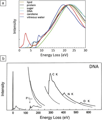
Information about the composition of biological specimens can be found throughout the electron energy-loss spectrum. The low-loss spectrum (0–20 eV) contains fine structures arising from excitations of molecular energy levels, which can be used to estimate the relative amounts of water, proteins, nucleic acids, sugars, and other components in frozen hydrated preparations (Figure 1a).Reference Sun, Shi, Hunt and Leapman7 Due to beam damage, this type of chemical information can only be determined on scales of around 50 nm or greater. At smaller scales, it is not possible to collect a sufficient EELS signal without first degrading the chemical composition of the specimen due to the effects of electron irradiation. The low-loss spectrum also provides a simple way of determining the specimen mass per unit area by measuring the fraction of transmitted electrons that are not inelastically scattered.Reference Leapman, Fiori and Swyt8 It is then possible to combine this measurement with EELS to determine the mass of a specific element per unit area and thereby calculate the elemental concentration, which in the case of cellular structures is often expressed in units of moles per liter of water or moles per kilogram total mass.
Typical electron energy-loss spectra from biological compounds. (a) Low-loss spectra up to an energy loss of 30 eV from major cellular components after processing to remove plural inelastic scattering (from Reference Reference Sun, Shi, Hunt and Leapman7). (b) Electron energy-loss spectra up to energy loss of 650 eV from DNA deposited on a thin carbon film, showing core edges of phosphorus, carbon, nitrogen, and oxygen.

Signals from core edges provide quantitative information about a range of endogenous elements within biological structures. For example, phosphorus (L2,3 edge at 132 eV) reveals phosphate groups in nucleic acids or attached to phosphorylated proteins (Figure 1b).Reference Ottensmeyer9–Reference Colliex and Mory13 Sulfur (L2,3 edge at 165 eV) indicates the presence of proteins that are rich in cysteine or methionine residues, or sulfate groups attached to carbohydrates.Reference Leapman, Jarnik and Steven14 The ratios of the major constituents of organic molecules (C, N, and O) can be quantified by analyzing their K edges at 285 eV, 532 eV, and 400 eV, respectively, which provides additional compositional information.Reference Leapman and Ornberg15 Certain metal atoms occurring in biological specimens are detectable by sharp resonances (white lines) at their EELS core edges (e.g., the calcium L2,3 edge at 348 eV),Reference Shuman and Somlyo5, Reference Leapman, Hunt, Buchanan and Andrews16 and the iron L2,3 edge at 707 eV.Reference Leapman17 Calcium is a particularly important element that is involved in the regulation of numerous cellular processes and is referred to as a “second messenger” because chemical or electrical signals from the environment outside the cell are transmitted into calcium signals within the cell’s cytoplasm. The concentration of calcium in cellular compartments is typically a few millimoles per kg dry weight, corresponding to just tens of atomic parts per million. Shuman and Somlyo’s pioneering work in the 1980s to develop a prototype EELS parallel detectorReference Shuman18 for measurement of trace levels of calcium eventually led to commercial EELS systems with subsequent benefit to the wider scientific community, including materials scientists.Reference Krivanek, Ahn and Keeney19
EELS can also be applied to detect exogenous elements such as cadmium and selenium in quantum dots, which have been developed as subcellular optical imaging probes,Reference van Schooneveld, Gloter, Stephan, Zagonel, Koole, Meijerink, Mulder and de Groot20 or metals such as gadolinium used for medical imaging.Reference Sousa, Aronova, Wu, Sarin, Griffiths and Leapman21 There is growing interest in developing the fields of nanomedicine and theranostics, including bio-nanomaterials that combine therapeutic and diagnostic imaging capabilities, such as hybrid nanoparticles containing inorganic and organic components. EELS and energy filtering are proving to be valuable techniques for analyzing such materials.
As in the case of the valence electron energy-loss spectrum, fine structures at the K edges of carbon, nitrogen, and oxygen also provide chemical fingerprints of biological molecules such as bases in nucleic acids and amino acids in proteins.Reference Isaacson and Johnson6 In practice, it has been difficult to exploit this information due to radiation damage. EELS can be valuable for understanding radiation damage phenomena in biological/organic materials—knowledge that is potentially relevant to fundamental limits of cryo-electron microscopy for structural biology. For example, it has been possible to characterize the composition of bubbles released on irradiation of frozen-hydrated biological samples in the electron microscope and to discover that these bubbles are composed of molecular hydrogen gas, which is evident by the appearance of the hydrogen K edge at 13 eV.Reference Leapman and Sun22 Other studies have elucidated the fate of oxygen on irradiation of frozen hydrated organic specimens.Reference Aronova, Sousa and Leapman23
The purpose of this review is to describe EELS and energy-filtering techniques for analyzing biological materials and to illustrate these capabilities by means of some applications. We also discuss the issue of detection limits and indicate some possible future directions for research.
STEM-EELS versus EFTEM
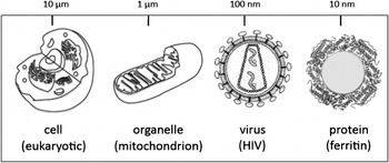
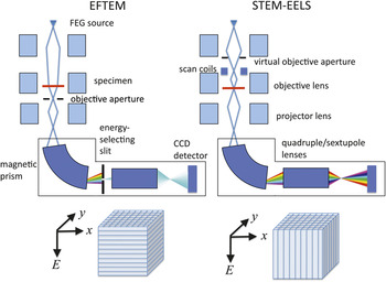
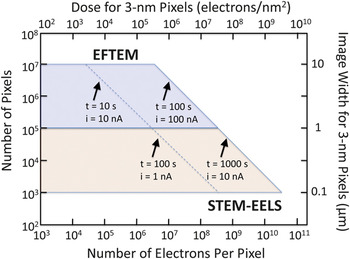
The complexity of biological systems manifests itself by many different types of organelles or supramolecular assemblies existing within a cell, such that particular structures of interest are often sparsely distributed. In general, it is necessary to analyze relatively wide areas, covering, for example, entire sections through cells of dimensions 5 or 10 μm (Figure 2). Moreover, there tends to be a natural variability in composition of an organelle of a given type due also to the complexity of the physiological processes that occur within cells. This necessitates analysis of many structures to obtain statistically significant quantitative data about their elemental or chemical composition and to determine how that composition changes when physiological conditions are altered. In the energy filtered transmission electron microscopy (EFTEM) mode of acquiring EELS data, a slit is inserted into the energy dispersion plane of the spectrometer so that images are acquired one energy loss at a time.Reference Ottensmeyer9, Reference Krivanek, Gubbens, Dellby and Meyer24 EFTEM acquisition satisfies the requirement of allowing large regions to be analyzed. However, there is a trade-off due to the restricted spectral information that is available. For certain applications, it is essential to employ the high efficiency of the STEM-EELS imaging mode, whereby a focused probe is scanned across the specimen, and multichannel spectra are collected at each pixel in a hyperspectral image.Reference Jeanguillaume and Colliex25, Reference Hunt and Williams26 The focusing of a nanoampere current into a nanometer diameter probe, which is typical in STEM analysis, requires a high-brightness field-emission source. Use of the STEM-EELS mode is essential when radiation damage is the limiting factor, as for imaging chemical compositions. such as water and protein content.Reference Sun, Shi, Hunt and Leapman7 Similarly, when the total number of incident electrons per unit area is the limiting factor (e.g., for detecting trace concentrations of calcium), the STEM-EELS acquisition mode is also essential.Reference Shuman and Somlyo5, Reference Leapman, Hunt, Buchanan and Andrews16Figure 3 compares the microscope configurations for the EFTEM and STEM-EELS modes and shows how the three-dimensional spectrum-image data are accumulated. There is clearly a limit to the maximum area that can be analyzed by scanning the probe and reading out the signal at each pixel. Typically, a STEM-EELS image contains of the order of 100 × 100 pixels, which corresponds to an acquisition time of around 1000 s for a read-out time of 100 ms per spectrum. Before selecting the optimal acquisition mode for a particular application, it is useful to consider the total number of pixels and the number of incident electrons per pixel that are accessible for the EFTEM and STEM-EELS imaging techniques. Such a plot is presented in Figure 4, which shows the complementarity of the two techniques: EFTEM typically provides image sizes of between 105 and 107 pixels, depending on the binning factor (i.e., the number of adjoining pixels that are pooled together) to acquire an image with the CCD camera; and STEM-EELS provides image sizes of between 103 and 105 pixels. For a 3-nm pixel size, this corresponds to image widths between 1 to 10 μm for EFTEM and between 0.1 and 1 μm for STEM-EELS.
Different lengths on a logarithmic scale for electron energy-loss spectroscopy analysis of biological structures in the range from tens of micrometers to nanometers, which includes cells, organelles, viruses, and large protein assemblies.

A comparison of techniques for compositional imaging in a transmission electron microscope capable of operating in the energy-filtered transmission electron microscope (EFTEM) mode and in the scanning transmission electron microscope (STEM) mode together with an electron energy-loss spectrometer (EELS) and a field-emission gun (FEG). The instrument shown is equipped with a post-column imaging filter, although an in-column filter can also be used. To perform EFTEM, images covering a window of energy losses defined by the energy-selecting slit are collected in parallel on a CCD (charge-coupled device) camera. In STEM-EELS, the energy-selecting slit is removed, and a spectrum is collected in parallel at each pixel successively in a raster-scanned image. The three-dimensional (x, y, E) data sets are built up as shown.

Comparison of compositional imaging using energy-filtered transmission electron microscope (EFTEM) and scanning transmission electron microscope-electron energy-loss spectra (STEM-EELS) imaging modes, showing the availability of total numbers of pixels and numbers of incident electrons per pixel. Examples of total acquisition times and beam or probe currents are indicated by diagonal lines. The total image width for 3-nm pixels is shown on the right vertical axis, and the total electron dose for 3-nm pixels is shown on the top horizontal axis. Note that for a given dose, the signal is always higher in STEM-EELS because the spectral information in EFTEM must be collected serially.

Application of EFTEM to map elements in cells
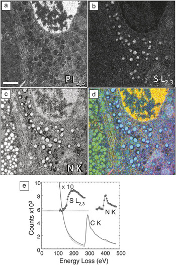
In principle, the most accurate method for obtaining quantitative elemental maps from large areas of sectioned cells is to acquire a series of EFTEM images successively over a range of energy losses spanning several core edges. In this EFTEM spectrum-imaging mode, the signal is limited by the width of the energy-selecting slit, which is usually set to the required energy increment in the spectrum image. Such an approach is illustrated by mapping the composition of secretory cells in pancreatic islets of Langerhans, which are aggregates of endocrine cells that secrete hormones to control blood glucose levels. Figure 5 shows phosphorus L2,3, sulfur L2,3, and nitrogen K maps from a region of a mouse islet that includes parts of an insulin-secreting beta cell and a glucagon secreting alpha cell.Reference Goping, Pollard, Srivastava and Leapman27 High levels of phosphorus (Figure 5a) are evident in the beta cell nucleus located at the top of the image, as expected from the high DNA content in the chromatin of nuclei. The granules in this insulin-secreting beta cell (right side of image) exhibit a high sulfur concentration (Figure 5b) consistent with the insulin polypeptide, which contains six cysteine amino acids. In contrast, no significant sulfur is evident in the granules of a glucagon-secreting alpha cell on the left side of the image, which is consistent with the much lower sulfur content of glucagon. Nitrogen, which serves as a general marker for protein, nucleic acid, and other biomolecules, is observed at a high concentration in both the alpha and beta granules, as well as in the nucleus (Figure 5c). An overlay of the phosphorus, sulfur, and nitrogen (Figure 5d) shows the relationship among the different cellular components.Reference Goping, Pollard, Srivastava and Leapman27 The availability of extractable EELS data from EFTEM spectrum images makes it possible to extrapolate the background reliably under the weak sulfur edge, as shown in Figure 5e, and thus allows us to quantify the composition of individual secretory granules. An average ratio of sulfur to nitrogen in the beta cell granules of 0.093 ± 0.015 (± SD) was obtained, which is consistent with a nominal value of 0.097 based on the known chemical formula. It should be appreciated, however, that EFTEM collection of spectrum-image data is inherently inefficient because most of the inelastically scattered electrons are discarded by the energy-selecting slit. In general, it is preferable to limit the number of EFTEM images acquired from beam sensitive materials.
Energy-filtered transmission electron microscope spectrum imaging of unstained epon (i.e., plastic-embedded) section of pancreatic islet of Langerhans obtained with 5 eV energy loss increments over a 400 eV energy range.Reference Goping, Pollard, Srivastava and Leapman27 (a) Phosphorus L2,3 edge image showing high P concentration in chromatin of a cell nucleus. (b) Sulfur L2,3 edge image showing high concentration of S in secretory granules of an insulin-producing beta cell, but low concentration of S in secretory granules of a neighboring glucagon-producing alpha cell. (c) Nitrogen K edge image showing a strong N signal in granules of both cell types, as well as in the beta cell nucleus. (d) Overlay of the elemental maps with P (red), S (blue), and N (green); scale bar = 1 μm. (e) Extracted EELS spectrum from beta cell secretory granule illustrating how quantitative analysis can be performed to determine the atomic ratio of sulfur to nitrogen of 0.108:1. The dotted line corresponds to zero counts for the background-subtracted sulfur and nitrogen edges, which are displayed with a 10-fold increase in vertical scale.

Application of STEM-EELS to map chemical composition
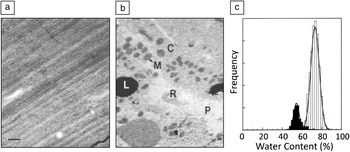
The radiation sensitivity of biological compounds and the subtle differences in an EELS fine structure associated with compositional variations imply that mapping the distributions of biological compounds in cells requires highly efficient and precise collection of spectral data at each pixel in an image. The strongest EELS signal originates in the valence electron excitation spectrum (Figure 1a), which has to be acquired in parallel with a STEM-EELS approach. Figure 6 illustrates the use of valence EELS imaging to map the distributions of water and protein in a frozen hydrated cryosection of rat liver.Reference Sun, Shi, Hunt and Leapman7 The low-dose annular dark-field STEM image in Figure 6a shows only compression artifacts caused by the cutting process. After acquiring a 128 × 128 pixel STEM-EELS spectrum image, then deriving single scattering distributions and fitting reference spectra at each pixel using a least squares algorithm, it was possible to obtain the distribution of water and protein shown in Figure 6b. Features of the hepatocyte ultrastructure now become visible, including mitochondria (M), cytoplasm (C), and lipid droplets (L), as well as a blood vessels containing plasma (P) and red blood cells (R). Quantitative water measurements of these compartments were obtained by normalizing the single scattering reference spectra to the respective total inelastic scattering cross-sections for water and protein. This results in a water content of 75 ± 3% for the cytoplasm and 57 ± 2% for the mitochondria. The total dose for the measurements was <2 × 10³ electrons/nm2, and the pixel size was 80 nm. Low energy-loss STEM-EELS has been applied successfully to map distributions of water across various cell layers in skin tissues.Reference Yakovlev, Misra, Shi, Firlar and Libera28, Reference Sousa, Aitouchen and Libera29
Water mapping of a frozen hydrated cryosection of rat hepatocytes obtained using a dedicated VG Microscope HB501 STEM equipped with a Gatan Model 666 EELS.Reference Sun, Shi, Hunt and Leapman7 (a) Low dose-dark-field scanning transmission electron microscope image showing no contrast apart from compression lines due to sectioning. (b) Water map generated by multiple least squares fitting of water and protein reference spectra (see Figure 1a) revealing mitochondria (M) and cytoplasm (C), as well as a blood vessel containing plasma (P) and a red blood cell (R). In both (a) and (b), the scale bar = 1 μm. (c) Analysis of regions of cytoplasm (light bars) and mitochondria (dark bars) showing water content of 75% and 57%, respectively.

Application of STEM-EELS for high-sensitivity elemental mapping
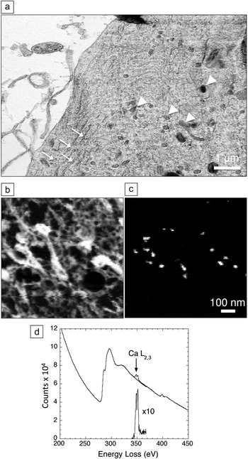
Mapping of elements that occur at low concentration, such as calcium, often requires delivery of more than 109 electrons into each pixel and, as evident from Figure 4, STEM-EELS has an important advantage for such applications.Reference Shuman and Somlyo5, Reference Leapman, Hunt, Buchanan and Andrews16 In addition, parallel collection of the spectrum in STEM-EELS enables precise modeling of the background, which is essential for reliable extraction of weak signals. An example of the application of STEM-EELS to measure subcellular calcium is a study of the role that different organelles play in buffering calcium in neurons that have undergone stimulation by depolarization of their plasma membranes.Reference Hongpaisan, Pivovarova, Colgrove, Leapman, Friel and Andrews30 A dehydrated cryosectioned frog sympathetic neuron in Figure 7a reveals good preservation of structure, including mitochondria and endoplasmic reticulum. Spectrum images were collected with a beam voltage of 100 kV, an incident probe current of 1 nA, and an acquisition time of 0.4 s per pixel, from a micrometer-sized region of the neuron.Reference Hongpaisan, Pivovarova, Colgrove, Leapman, Friel and Andrews30 This resulted in the carbon K-edge and calcium L2,3 images, as shown in Figure 7b–c, respectively. Focal concentrations of calcium are found to be associated with the mitochondria, implying a role for these organelles in buffering calcium under the specific physiological conditions of these isolated and cultured sympathetic neurons. The EELS data extracted from one such focal spot in Figure 7d show how the background was fitted using an inverse power law and extrapolated into a 10 eV post-edge energy window that included the Ca L2,3 white line resonance. The average mitochondrial calcium concentration was quantified and showed a gradient with a decreasing concentration toward the center of the cell.Reference Hongpaisan, Pivovarova, Colgrove, Leapman, Friel and Andrews30 EFTEM can also be used to map the distribution of calcium in dehydrated cryosectioned cells if care is taken to correct for plural inelastic scattering, which affects the shape of the background intensity underlying the calcium L2,3 edge.Reference Aronova, Kim, Pivovarova, Andrews and Leapman31 This is accomplished by recording the unfiltered image I tot and zero-loss image I 0 and then calculating the relative thickness, t/Λ = ln(I tot/I 0) at each pixel, where Λ is the inelastic mean free path. The shape of the core-edge background can be modeled as a function of relative thickness to provide a correction to the simple two-window calcium map, which is based on a constant ratio between the pre-edge background and the background at the Ca L2,3 edge. The limited number of incident electrons per pixel in EFTEM relative to that in STEM-EELS makes it necessary to average the Ca L2,3 signal over many pixels to detect low concentrations in EFTEM.
Scanning transmission electron microscope-electron energy-loss spectroscopy (STEM-EELS) mapping of calcium in cultured frog sympathetic neuron.Reference Hongpaisan, Pivovarova, Colgrove, Leapman, Friel and Andrews30 (a) Low-dose dark-field STEM image (contrast inverted) showing preservation of membranes, endoplasmic reticulum (arrows), and mitochondria (arrowheads) in a freeze-dried cryosection. (b) Carbon K edge image from several mitochondria. (c) Calcium L2,3 edge image extracted from spectrum-image data; image widths in (b) and (c) are the same. (d) EELS from calcium inclusion in mitochondrion showing extrapolation and subtraction of the background under the edge.

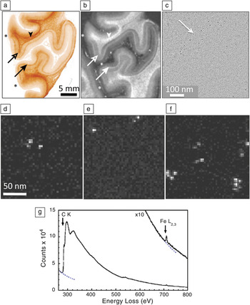
Another example in which STEM EELS has proven useful is for studying the distribution of superparamagnetic iron in the human brain to determine whether this element contributes toward contrast in magnetic resonance imaging (MRI).Reference Fukunaga, Lia, van Gelderen, de Zwarta, Shmuelia, Yaoa, Lee, Maric, Aronova, Zhang, Leapman, Schenck, Merkle and Duyn32Figure 8a shows a paraffin section of post-mortem human visual cortex stained for iron with Perls stain, and Figure 8b shows the R2* MRI relaxation image contrast corresponding to the inverse of the decay time of the nuclear magnetic resonance signal caused by spin-spin interactions; both images show a strong band of contrast that is associated with a brain structure known as the line of Gennari, which is an anatomical feature in the visual cortex. Regions of unstained visual cortex that included the line of Gennari were embedded in plastic and sectioned to a thickness of 100 nm. Phase-contrast TEM images (Figure 8c) show clusters of particles with an approximate diameter of 5 nm. STEM-EELS spectrum images (Figure 8d‒f) collected from randomly selected areas revealed that these particles contained iron, as confirmed by spectra extracted from the particles (Figure 8g).Reference Fukunaga, Lia, van Gelderen, de Zwarta, Shmuelia, Yaoa, Lee, Maric, Aronova, Zhang, Leapman, Schenck, Merkle and Duyn32 A quantitative analysis of the spectrum images showed that these particles contained 1740 ± 580 Fe atoms, which is consistent with the amount of iron expected in the molecular cores of the iron storage protein, ferritin. By counting the number of iron cores in each analyzed region, it was found that there were 50 ± 4 μg and 16 ± 7 μg of iron per gram of tissue, respectively, in the line of Gennari and superficial regions of the visual cortex. These values are consistent with the observed contrast in the MRI images.Reference Fukunaga, Lia, van Gelderen, de Zwarta, Shmuelia, Yaoa, Lee, Maric, Aronova, Zhang, Leapman, Schenck, Merkle and Duyn32
Application of scanning transmission electron microscope-electron energy-loss spectroscopy (STEM-EELS) to explain contrast observed in brain magnetic resonance images (MRI) in terms of iron concentrations.Reference Fukunaga, Lia, van Gelderen, de Zwarta, Shmuelia, Yaoa, Lee, Maric, Aronova, Zhang, Leapman, Schenck, Merkle and Duyn32 (a) Optical micrograph of post-mortem human visual cortex treated with Perl stain for iron, showing elevated iron in the region of the line of Gennari (arrows). (b) Corresponding R2* MRI, also showing contrast in the line of Gennari (arrows). Image widths in (a) and (b) are the same, and asterisks indicate boundaries of region of visual cortex. (c) Phase-contrast transmission electron microscopy of unstained section in the region of the line of Gennari showing electron-dense particles. (d‒f) STEM-EELS iron maps obtained from randomly selected areas of an unstained specimen in the vicinity of the line of Gennari, showing particles with high Fe content. (g) Typical EELS extracted from one of the Fe-containing particles is dominated by the carbon (C K edge) originating from the embedding medium and the protein, but it also reveals a strong Fe L2,3 edge; quantitative analysis showed that the particles contained on average 1740 ± 580 Fe atoms, consistent with the iron cores of ferritin molecules; dotted lines indicate extrapolated background intensity.

Application to nanomedicine
Recently, EELS has proven useful for analyzing synthetic bionanoparticles in the size range from about 1 to 100 nm, which are designed for medical diagnostic or therapeutic applications (i.e., in the field of nanomedicine). The technique can also be applied to analyze bionanoparticles that are created by incorporating multiple functional groups to provide both diagnostic and therapeutic functions together (i.e., “theranostic” nanoparticles). EFTEM and STEM-EELS can be used both to localize bionanoparticles within cells and tissues, as well as to characterize the composition and substructure of the nanoparticles themselves. Since the localization of nanoparticles can often be achieved with standard TEM or STEM imaging techniques based on elastically scattered electrons, we focus here on the spectroscopic characterization of the nanoparticles themselves. The biological functions of such nanoparticles tend to depend strongly on their dimensions and, in the case of multiphase particles, on their architecture. A large fraction of a nanoparticle’s atoms can be situated at the surface and therefore be chemically reactive, and quantum size effects can determine a nanoparticle’s physical properties, such as optical properties in the case of quantum dots. Until now, only a few types of nanoparticles have been medically approved for routine use in humans or in clinical trials (e.g., liposomes containing the anticancer drug doxorubicin and functionalized iron oxide particles for use in MRI imaging). However, there is also strong interest in other types of nanoparticles, which are not yet approved for medical use, including functionalized single-walled carbon nanotubes, quantum dots, hybrid organic/inorganic nanoparticles, and dendrimers. Since the function of bionanoparticles depends critically on their dimensions (i.e., surface to volume ratio), it is important to assess their degree of monodispersity (i.e., the spread in the distributions of their size, shape, and chemical composition). In the electron microscope, analysis of annular dark-field STEM images can provide the distribution of particle masses, whereas EFTEM or STEM-EELS provides the distribution of elemental or chemical composition.
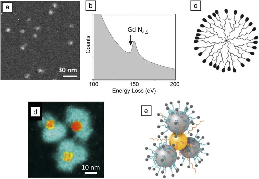
An example of a nanoparticle that has been used for MRI in animals is the polyamidoamine (PAMAM) dendrimer, which is conjugated to gadolinium diethylene triamine pentaacetic acid (Gd-DTPA), with the Gd atoms providing magnetic contrast. Dendrimers are branched macromolecules constructed around a central core unit by a series of repetitive steps, each of which results in a new generation of nanoparticle with a larger molecular diameter and a surface that contains typically twice the number of reactive sites as the previous generation. Figure 9a shows a gadolinium map from a G7 (seventh generation) PAMAM/Gd-DTPA, obtained by recording EFTEM images above and below the N4,5-edge (Figure 9b).Reference Sousa, Aronova, Wu, Sarin, Griffiths and Leapman21 Quantitative analysis gives an estimate of the number of Gd atoms per particle and reveals that the dendrimer particles (illustrated in Figure 9c) contain a mean of 266 ± 50 Gd atoms, where the uncertainty is attributed mainly to counting statistics in the EFTEM images. STEM data indicate that the total particle mass is 330 ± 40 kilodaltons, and approximately 300 of the 512 terminal groups are conjugated to DTPA (data not shown), implying that almost 90% of the DTPA molecules are bound to gadolinium. These measured distributions of mass and composition indicate a relatively high degree of monodispersity. The size of the dendrimer nanoparticles is just sufficient to pass through the pores of leaky blood vessels that occur in tumors, and these PAMAM/Gd-DTPA nanoparticles have therefore been used to obtain MRI images of brain tumors in mice injected intravenously with the reagent.Reference Sousa, Aronova, Wu, Sarin, Griffiths and Leapman21
Application of energy-filtered transmission electron microscope (EFTEM) and electron energy-loss spectra to the analysis of bionanoparticles. (a) EFTEM gadolinium N4,5 edge map of a generation-7 polyamidoamine (PAMAM) dendrimer conjugated with Gd3+ diethylene-triamine-pentaacetic-acid (DTPA); analysis of the Gd content reveals the degree of monodispersity and the number of gadolinium atoms (266 ± 4 sem) per nanoparticle.Reference Sousa, Aronova, Wu, Sarin, Griffiths and Leapman21 (b) Gd N4,5 edge obtained from a reference standard. (c) Schematic diagram of a dendrimer structure; peripheral densities represent conjugated DTPA molecules. (d) EFTEM iron L2,3 edge map of hybrid Au-Fe3O4 nanoparticles used to detect the presence of matrix metalloproteinase in cancer cells.Reference Xie, Zhang, Aronova, Zhu, Lin, Quan, Liu, Zhang, Choi, Kim, Sun, Lee, Sun, Leapman and Chen33 Cleavage of a substrate molecule bound to the iron oxide results in the release of a fluorescent dye; image reveals peripheral iron oxide particles surrounding central gold cores, which quench the fluorescent dye molecules until they are released following substrate cleavage. (e) Schematic diagram hybrid nanoparticle showing conjugation of enzyme substrate and dye to the Fe3O4 particles (large gray spheres) and thiol-modified polyethylene glycol attached to the gold (gold sphere); small peripheral spheres attached to the iron particles represent fluorescent dye molecules.
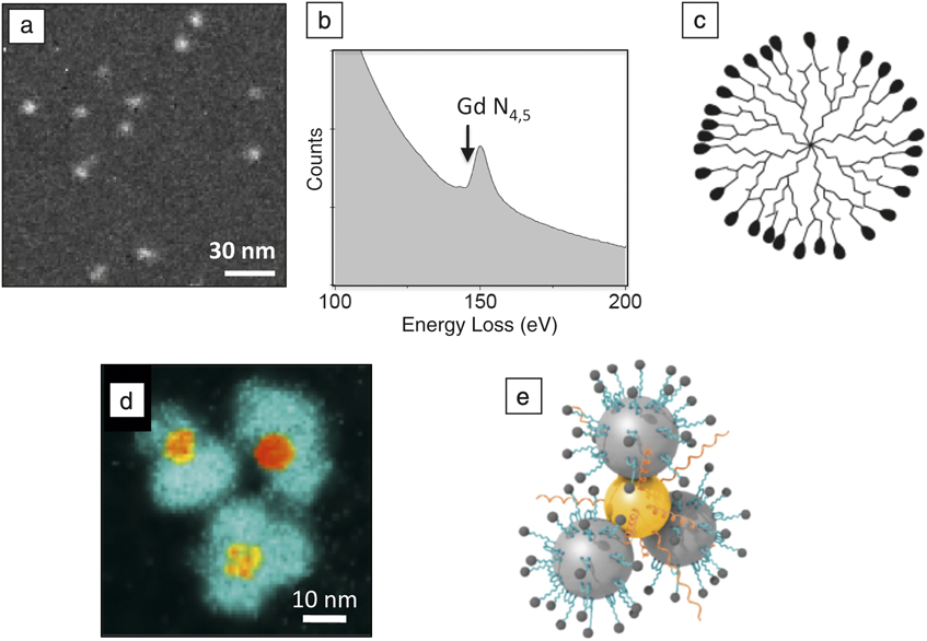
An example of a more complex hybrid nanoparticle (Figure 9d‒e) is a “flower-like” gold/iron oxide optical nanosensor that has been designed to detect a specific enzyme, matrix metalloproteinase (MMP), expressed by certain tumors. This nanoparticle has a central Au core attached to Fe3O4 particles in a flower petal arrangement. Organic molecules consisting of a polypeptide substrate for the MMP enzyme, coupled to a fluorescent dye Cy5.5, are anchored to the Fe3O4 by means of a linker.Reference Xie, Zhang, Aronova, Zhu, Lin, Quan, Liu, Zhang, Choi, Kim, Sun, Lee, Sun, Leapman and Chen33 In the absence of the enzyme, the fluorescent dye is quenched by the Au core of the nanoparticle, but when MMP is present, this enzyme cleaves off the dye molecule, which then fluoresces. Iron L2,3 EFTEM maps from the Au/Fe3O4 optical nanosensor particles (Figure 9d) show a flower-like morphology with iron-containing petals surrounding gold cores that are visible by their high electron density in zero-loss TEM images. The architecture of the nanoparticle is confirmed from the EFTEM analysis and, together with the particle’s 3D shape obtained from electron tomography (data not shown), leads to a model for the particle structure in Figure 9e. These Au/Fe3O4 optical nanosensors have been used successfully to image head and neck cancers in mice.Reference Xie, Zhang, Aronova, Zhu, Lin, Quan, Liu, Zhang, Choi, Kim, Sun, Lee, Sun, Leapman and Chen33
Another functionalized hybrid bionanoparticle that has been analyzed in even greater detail by STEM-EELS at the sub-nanometer scale is a 30-nm diameter silica nanoparticle containing a 7-nm diameter CdSe quantum dot at its core.Reference van Schooneveld, Gloter, Stephan, Zagonel, Koole, Meijerink, Mulder and de Groot20 These authors are not only able to characterize the inorganic components but also are able to obtain information about the chemical bonding of the nanoparticle’s organic surface coating consisting of lipid, hydocarbon, and Gd-DTPA, which has the potential to provide dual optical and MRI imaging modalities.
Imaging elemental distributions in 3D
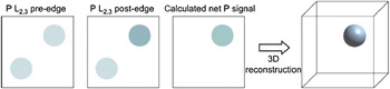
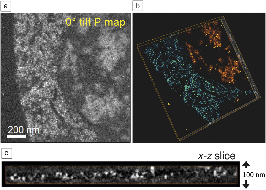
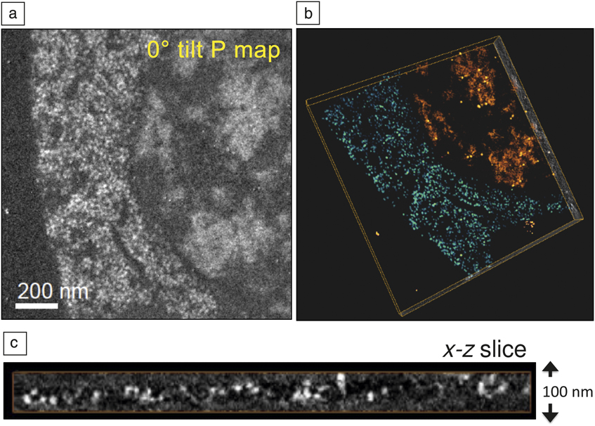
Three-dimensional elemental maps can be obtained by collecting tomographic tilt series below and above a core edge.Reference Midgley and Weyland34–Reference Boudier, Lechaire, Frébourg, Messaoudi, Mory, Colliex, Gaill and Marco36 In beam sensitive materials, it is possible to utilize the principle of dose fractionation such that individual images in the tilt series can give rise to a 3D reconstruction with much improved statistics. Such an approach is used routinely in cryo-electron tomography,Reference Koster, Grimm, Typke, Hegerl, Stoschek, Walz and Baumeister37 and it can be applied to 3D elemental maps too.Reference Aronova, Kim, Harmon, Sousa, Zhang and Leapman38 It is crucial to align the images in the tilt series; this is achieved by depositing gold nanoparticles on the top and bottom surfaces of unstained plastic sections.Reference Kremer, Mastronarde and McIntosh39 We have applied this technique of quantitative electron spectroscopic tomography (QuEST) to map the 3D distributions of phosphorus in cell nuclei.Reference Aronova, Kim, Harmon, Sousa, Zhang and Leapman38 Phosphorus is a major constituent of nucleic acid (DNA and RNA) since phosphate groups link together the sugars that are bound to the bases on each strand of the helix. The 3D arrangement of phosphorus and nitrogen has the potential to provide information about the packing of DNA and protein assemblies; phosphorus is indicative of nucleic acid, whereas nitrogen is indicative of protein as well as nucleic acid. Of course, the meaningful spatial resolution is limited by radiation damage and specimen preparation. In the QuEST technique, one pre-edge and one post-edge P L2,3 images are acquired along with a t/Λ map obtained from an unfiltered and zero-loss image, which allows a correction for plural inelastic scattering to be made.Reference Aronova, Kim, Zhang and Leapman40Figure 10 indicates the procedure for deriving the phosphorus maps for each angle in the tilt series, and then for obtaining the 3D phosphorus distribution by tomography reconstruction. Figure 11 shows the application of QuEST to map the distribution of nucleic acid in a cell from a 100-nm section of the organism Caenorhabditis elegans. Reference Aronova, Sousa, Zhang and Leapman41 Because of the need to quantify the elemental distributions, we have used a simultaneous iterative reconstruction technique (SIRT) algorithm,Reference Midgley and Weyland34 rather than the more standard Fourier back-projection algorithm.Reference Koster, Grimm, Typke, Hegerl, Stoschek, Walz and Baumeister37Figure 11a‒b shows, respectively, the projected phosphorus map at a tilt angle of 0° and a volume reconstruction of regions of cytoplasm (blue/green) and nucleus (orange/red). An x-z slice through the cytoplasm reveals RNA-containing ribosomes dispersed throughout the thickness of the section (Figure 11c); each ribosome is found to contain approximately 7000 P atoms, which is consistent with the known value. Quantitative analysis of phosphate in the cell nucleus has the potential to yield information about the packing density of DNA.
Simplified diagram showing determination of a 2D phosphorus map by subtracting a suitably scaled energy-filtered transmission electron microscope pre-edge image from a post-edge image, and then the determination of a 3D phosphorus map from a tomographic reconstruction of a 2D phosphorus tilt series.Reference Aronova, Kim, Harmon, Sousa, Zhang and Leapman38 Two features are shown in the pre-edge and post-edge images, but only the one at the top right contains phosphorus.

Determination of 3D distributions of phosphorus using quantitative electron spectroscopic tomography (QuEST).Reference Aronova, Sousa, Zhang and Leapman41 (a) Phosphorus map at zero tilt angle from unstained, embedded, and sectioned cell of Caenorhabditis elegans. (b) Volume rendered tomogram obtained using the simultaneous iterative reconstruction technique showing two regions of high phosphorus content: cytoplasm containing ribosomes (blue/green) and nucleus (orange/red) containing areas of densely packed chromatin; full width of box is 1.5 μm. (c) x-z slice extracted from the reconstructed volume shows the roundness and clarity of ribosomes in 3D.
Detection limits
When the probe size is reduced to a 1-nm diameter, STEM-EELS can provide near single atom detection of biologically important elements such as calcium and iron.Reference Leapman17, Reference Mory and Colliex42 By considering the inelastic cross-sections for core-edge excitation as well as the cross-sections for the EELS background corresponding to the high energy tails of valence electron excitations and lower energy core-edges, an approximate expression for the minimum detectable number of atoms pX of element X can be written as:Reference Leapman and Ahn43
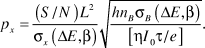
Here, L is the probe size; h is a constant in the range of 3–10 that depends on the shape of the background underlying the core edge; η is the detective quantum efficiency of the detector; I 0 is the incident probe current; τ is the integration time; e is the electron charge; (S/N) is a specified signal-to-noise ratio; σX(ΔE,β) is the inelastic cross-section for the core excitation of element X for collection of semi-angle β and integrated over energy window ΔE; σB(ΔE,β) is the inelastic cross-section for the background in the same spectral energy window originating from matrix atoms B; and nB is the number of matrix atoms per unit area.
By using Equation 1, we estimate that it should be possible to detect single atoms of iron and calcium bound to macromolecular assemblies supported on a 3 nm carbon film, with a S/N = 3 for Fe and a S/N = 7 for calcium, for a 1-nm diameter probe, a beam energy of 100 keV, and a total incident charge of 0.4 nC.Reference Leapman17 These predictions have been confirmed by experiment, but such measurements require an extremely high electron dose of >109 electrons per nm2. At these doses, knock-on damage can result in severe mass loss from thin specimens, as has been demonstrated in the analysis of graphene and single-walled carbon nanotubes.Reference Krivanek, Chisholm, Nicolosi, Pennycook, Corbin, Dellby, Murfitt, Own, Szilagyi, Oxley, Pantelides and Pennycook44 Knock-on damage will also be relevant for nanoscale analysis of isolated macromolecules supported on thin carbon substrates. For this type of specimen, operation at 60-keV beam energy could be advantageous.Reference Egerton, Wang and Crozier45
Future directions and conclusions
Advances in electron energy-loss spectroscopy (EELS) instrumentation and processing methods now enable a range of compositional information to be obtained from biological materials. The latest generation of intermediate voltage transmission electron microscopes with beam energies of 200 or 300 keV provides the complementary approaches of energy-filtered transmission electron microscope (EFTEM) and scanning transmission electron microscope (STEM)-EELS in a single instrument. The technique of choice depends on the application and the type of information that is needed (e.g., field of view, concentration range, chemical, elemental and three-dimensional composition, and susceptibility of the specimen to radiation damage). Recently, the sensitivity of energy-dispersive x-ray spectroscopy (EDXS) has increased by a factor of about ten with the advent of silicon drift detectors,Reference Somlyo, Broderick, Shuman, Buhle and Somlyo46 which have collection solid angles approaching 1 steradian and maximum count rates of greater than 5 × 10⁵ s‒1, so that simultaneous STEM-EELS and STEM-EDXS is now feasible, with each technique being more sensitive for a specific range of elements. For example, STEM-EDXS can be used to map the distributions of Na, K, and Mg in cryosectioned cells, whereas it is difficult to analyze these elements by STEM-EELS because of their unfavorable edge shapes.Reference Schlossmacher, Klenov, Freitag and Harrach47 In the future, correlative imaging techniques are also likely to increase in importance as attempts are made to identify specific bound elements and biological molecules in cellular structures. In that regard, the use of a dual-function probe such as fluoro-nanogold allows the detection of specific proteins of interest in the fluorescence optical microscope, after which the same proteins can be localized in the electron microscope using electron-dense gold labels.Reference Powell and Hainfeld48, Reference Robinson and Takizawa49 Fluoro-nanogold labeling can also be combined with EFTEM mapping to correlate the distribution of specific classes of biomolecules with an intrinsic marker such as phosphorus to image the distribution of nucleic acid. Both EFTEM and STEM-EELS are also finding applications in nanomedicine and theranostics, in which hybrid inorganic/organic nanoparticles can be characterized to determine their structures and degrees of monodispersity. For some applications, STEM-EELS provides single atom sensitivity for detecting bound elements attached to macromolecular assemblies. It is not yet clear to what extent radiation damage will limit such applications, but it might be necessary to reduce knock-on damage by lowering the beam voltage.
Acknowledgments
This work was supported by the Intramural Research Programs of the National Institute of Biomedical Imaging and Bioengineering, National Institutes of Health. The authors thank Dr. Alioscka Sousa (NIBIB, NIH) and Dr. S. Brian Andrews (NINDS, NIH) for valuable discussions and Dr. Guofeng Zhang for his help with specimen preparation.