
Introduction
Thermal barrier coating (TBC) is a protection system that increases the efficiency of gas turbine engines and extends the life of metal parts [Reference Clarke, Oechsner and Padture1, Reference Darolia2]. TBCs consist of different layers, such as a bond coat (BC). The BC is usually a nickel-based alloy used as Al reservoir to form thermally grown oxides (α-Al2O3, TGO), and the top coat (TC) is 7YSZ, which is usually 7–8 wt% Y2O3-doped ZrO2 [Reference Clarke, Oechsner and Padture1, Reference Darolia2, Reference Stiger, Yanar, Topping, Pettit and Meier3, Reference Peters, Leyens, Schulz and Kaysser4, Reference Levi5]. MCrAlY is used more and more in moist air or high water vapor industrial gas. Interaction with MCrAlY-coated turbine blades leads to the formation of a spinel environment on the overlay [Reference Sullivan and Mumm6]. Therefore, the investigation of oxidation behavior of MCrAlY-coated turbine blades in high-temperature water environment is of great significance [Reference Yan, Guo and Gong7].
Protection from oxidation and hot corrosion of alloys is based on a dense, continuous, slowly growing layer of relatively chemical inertia and adherent oxide scales [Reference Hou8, Reference Pint, Treska and Hobbs9]. The thermal growth oxide (TGO) layer in TBC usually exists as alumina (α-Al2O3) on aircraft and industrial gas turbine engines at high temperatures [Reference Padture10, Reference Veal, Paulikas and Hou11]. It has been proved that water vapor is one of the important factors that affect the growth of alumina layer. Huang et al. [Reference Huang, Bergholz, Mauer, Vassen, Naumenko and Quadakkers12] found that in Ar + H2 + H2O environment, the oxidation rate of the coating would be lower than that in Ar + O2. In addition, atmospheres had an important effect on the phase transition from θ-to α-Al2O3: accelerated phase transition by a rapid diffusion process of oxygen. The oxidation process of NiAl alloys in different atmospheres (15% H2O + Ar, 20% O2 + Ar, and 15% H2O + 17% O2 + Ar) at 1100 °C was investigated [Reference Xiong, Li and Li13]. Davis et al. [Reference Davis and Tomozawa14] found that water diffusion affects the network structure of silica, and Peng Song et al. [Reference Song, He, Xiong, Ma, Song, Lü and Lu15] found that the oxide generated by NiCoCrAl alloy after water vapor oxidation had good adhesion. Oxygen active elements are separated from the grain boundaries of metal oxide and alumina in TGO due to the outward diffusion of oxygen potential gradient, which hinders the movement of cations and inhibits the outward diffusion of Al3+ ions. It is pointed out that the diffusion of oxygen caused by charge compensation reaction leads to the diffusion of Al3+ [Reference Heuer, Nakagawa, Azar, Hovis, Smialek, Gleeson, Hine, Guhl, Lee, Tangney, Foulkes and Finnis16, Reference Heuer, Hovis, Smialek and Gleeson17]. Therefore, the alumina layer is mainly increased by the inward migration of oxygen anions. Many experimental results show that exposure to high-temperature water vapor accelerates the diffusion of oxygen in polycrystalline alumina [Reference Heuer18, Reference Preis and Sitte19]. To study the oxidation resistance of MCrAlY alloys in different atmospheres, several systems were used, including air and air containing water vapor.
Many different compositions of MCrAlY coatings are available on the market, and Y is a well-known RE dopant and can improve the adhesion of alumina scale, but in addition to Y, different dopants can also be added [Reference Hussain, Qureshi, Shahid, Chughtai and Khalid20]. The “dynamic separation theory” (Al and Hf plasma diffuse outward and O diffuses inward, forming a TGO layer between the YSZ layer and the alloy layer, which will prevent oxygen from entering and reduce oxidation rate. The whole process is a dynamic process) explains the “RE effect” (John Stringer (1934–2014) created the “reactive elements” (RE) effect to replace the “rare earth” effect to better capture the beneficial effects of oxygen active additives (such as Y, La, Ce, and Hf) on high-temperature oxidation). RE effect is mainly summarized through the influence of the adhesion, growth, and microstructure of oxide skin. Whittle and Stringer have listed more Re effects (mainly chromium-forming alloys) [Reference Whittle and Stringer21]:
(i) Improved selective oxidation and faster scale nucleation
(ii) Reduction in scale growth rate
(iii) Change in the scale growth mechanism from metal to predominant oxygen diffusion
(iv) Suppression of void formation at the scale/alloy interface, and
(v) Improved scale adherence
In some papers, the effectiveness of reactive elements (RE) in reducing the growth rate of alumina can be explained by the binding strength of metal oxygen (M-O) [Reference Pint22]. It was reported that the combination of Y and Hf can improve the performance of the coating, and further adding Hf to the MCrAlY coating (containing two or more other RE dopants) can improve the oxidation behavior [Reference Gupta, Duvall and Gell23]. Zang et al. [Reference Zang, Song, Feng, Xiong, Chen, Liu and Lu29] found that the nickel-based superalloy DZ125 hot-dipped with Al coatings doped by Si had an effect on the oxidation life. In addition, Taihong Huang et al. [Reference Huang, Naumenko, Song, Lu and Quadakkers30] found that doping Ti would have an impact on the growth mechanism of alumina. To improve the oxidation properties of NiAl coatings (without TBC), BCs or superalloys containing Hf, Zr, or Y usually provide the long lifetime and the optimum content of rare earth elements (Hf, Zr, or Y) is also determined [Reference Pint22, Reference Pint, Wright, Lee, Zhang, Prüβner and Alexander24, Reference Li, Guo, Wang, Zhang, Gong and Xu25, Reference Pint, Haynes and Zhang26, Reference Guo, Li, Zheng, Gong and Xu27, Reference Yan, Guo and Gong28]. The interface adhesion, stability, and mechanical strength of the α-Al2O3/β-NiAl interface were compared by different RE doping levels, and Hf could improve the adhesion between TGO and the adhesive coating (Ni45.2, 20Cr, 12Al, 22Co, 0.2Y, 0.6Hf wt%) because of the strong bonding between Hf and the adjacent oxygen atoms in alumina [Reference Munawar, Schulz and Shahid31]. Shang et al. [Reference Shang, Wang, Gleeson and Liu32] proposed that Hf is the best active element to prevent Al2O3 scale growth, because Hf–O has the highest binding energy. However, it is not clear whether HfO2 formation is different at high-temperature oxidation in different atmospheres, or whether the location of HfO2 affects the anti-oxidation activity. Therefore, this paper studied the effects of air and air containing water vapor on the oxidation resistance of MCrAlY-doped Hf, and the effect of HfO2 location on the TGO stress. The effects of atmosphere and the location of HfO2 are verified by an experiment on oxidation in air containing water vapor for 24 h.
Results
Oxidation kinetics
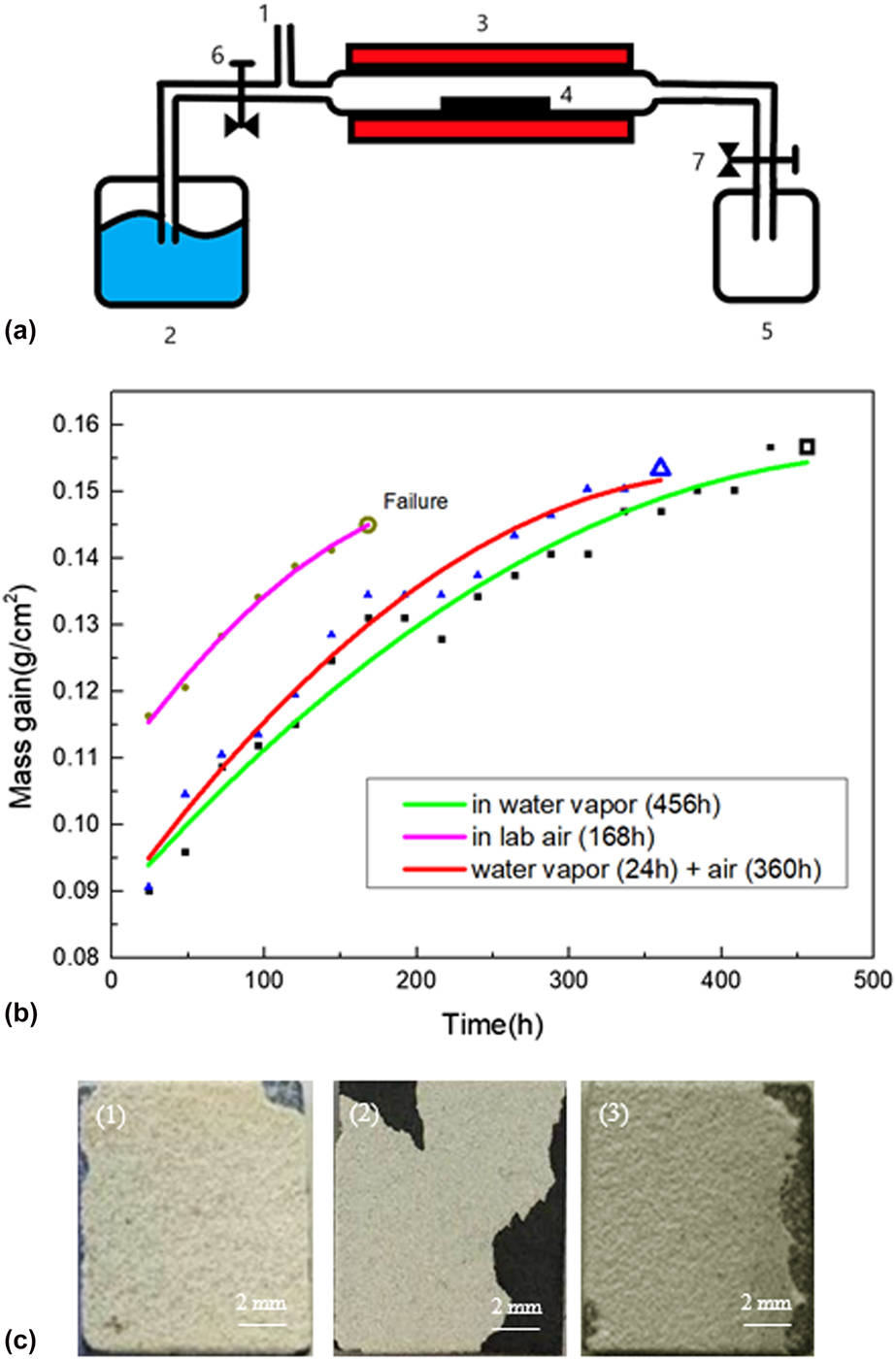
Figure 1(b) shows the cyclic oxidation kinetics of NiCoCrAlYHf samples at 1050 °C in air and air containing water vapor until failure. Figure 1(c) shows a macroscopic image of the failure after thermal cycling in different atmospheres. The cyclic oxidation curves of NiCoCrAlYHf alloys indicate that the mass gain of air containing water vapor is faster than air. The samples show a much lower oxidation lifetime in air than in air containing water vapor. In particular, in the simples first pretreated in air containing water vapor for 24 h and then oxidized in air at 1050 °C, the oxidation rate decreased significantly and the lifetime of the pretreated coating can be doubled compared to the coating in laboratory air only.
(a) Schematic illustration of oxidation in air and in air containing water vapor atmosphere installation. 1. Laboratory air, 2. thermocouple, 3. muffle furnace, 4. samples, 5. gas outlet, and 6, 7. valves; (b) mass gain curves of NiCoCrAlYHf specimen cyclic oxidation at 1050 °C; (c) macroscopic image of failure after thermal cycling in different atmospheres. (1) Air + water vapor, (2) air, (3) 24 h, water vapor + air.

The oxidation kinetics were fitted to obtain a fitting curve between time and mass gain [in Fig. 2(b)]. The fitting formulas are as follows:
 $$\eqalign{y = 0.10789 + 3.29003 \times {10^{ - 4}}x - 6.44885 \cr\times {10^{ - 7}}{x^2}\;\left( {{\rm{in}}\;{\rm{lab}}\;{\rm{air}}} \right)\quad ,$$
 $$\eqalign{y = 0.08759 + 3.17906 \times {10^{ - 4}}x - 3.88168 \cr\times {10^{ - 7}}{x^2}\;\left( {{\rm{in}}\;{\rm{water}}\;{\rm{vapor}}} \right)\quad ,$$
 $$\eqalign{y = 0.08787 + 2.593443 \times {10^{ - 4}}x - 2.48947 \cr\times {10^{ - 7}}{x^2}\;\left[ {{\rm{water}}\;{\rm{vapor}}\;\left( {24\;{\rm{h}}} \right) + {\rm{air}}} \right]\quad .$$
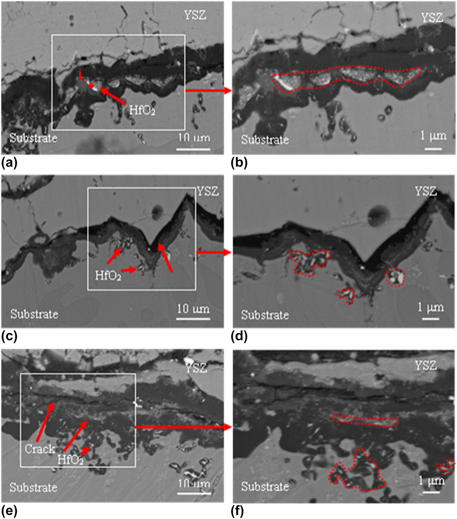
Cross-sectional BSE micrographs of NiCoCrAlHf alloys oxidized at 1050 °C in different atmospheres. (a, b) Water vapor, (c, d) air, and (e, f) 24 h, water vapor + air.

It is concluded that alumina has the lowest mass gain rate in the air containing water vapor, and oxidation in air after pretreatment for 24 h in air containing water vapor has similar quality growth trends to oxidation in air containing water vapor from the oxidation kinetic curve of the specimens.
Characteristics of cross sections
Figure 2 shows the cross section formed by the oxidation failure of the sample in air and air containing water vapor environment at 1050 °C. As shown in Fig. 2, a layer of alumina is formed between YSZ and the substrate after oxidation at 1050 °C and shows large amounts of HfO2 particles. It can be clearly observed that an HfO2-rich layer is formed in the alumina layer after oxidation in air containing water vapor and the alumina layer is dense [Figs. 2(a) and 2(b)]. The chemical composition of point 1 of the part in Fig. 2(a) is given in Table I. It proves that the white part is HfO2. Figure 2(c) shows that irregular and continuous cracks appear in TGO, and the HfO2-rich layer appears at the oxide/alloy interface. Meanwhile, the large interface fluctuation of the oxide layer was observed [Fig. 2(d)]. It can be clearly seen in Figs. 2(e) and 2(f) that the HfO2-rich layer is present at the alumina layer/ substrate interface and the TGO, and the alumina layer is thick and flat with fewer holes and long cracks.
Chemical composition of point 1 in the figures (at.% or ppma).

Discussion
Effect of partial element distribution on the defects within the oxide layer in different atmospheres
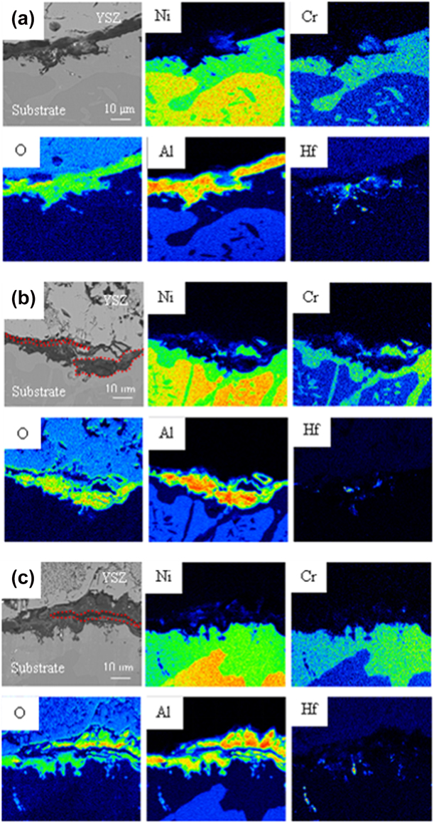
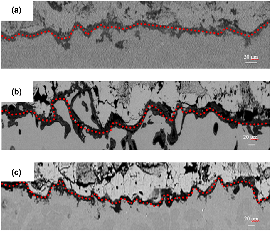
According to the cross sections of the samples in air and air with steam (Fig. 2), and combined with the results of EPMA analysis of the cross section (Fig. 3), the formation mechanism of defects is proposed and the corresponding conclusions are given. HfO2 pegs lead to the formation of holes within the oxide scale. The volume of the crystal will change during the growth of HfO2, and it can cause high stress at the interface of oxide/alloy/ceramic [Reference Li, Song, Khan, Feng, Chen, Zang, Xiong, Lü and Lu36]. HfO2 pegs form below the oxide scale in air, and alumina exhibits serious in-growth, promoting nonuniform stress distribution. Meanwhile, it can be seen from Fig. 3(b) that severe ingrowth occurs. The Al2O3 scale has showed a large fluctuation [Fig. 4(b)]. The fluctuation of oxide scale generates considerable internal stress within the layer. Therefore, the crack propagation is the result of stress development, and the existence of stress also affects the stripping of alumina layer and YSZ layer. We have discussed in detail the generation and development of cracks. HfO2 pegs are distributed within the oxide layer after oxidation in air containing water vapor, which can help to reduce the number of holes and cracks in TGO. Due to the low internal stress and slow growth, the alumina layer is relatively flat in Fig. 4(a). In air, the nonuniform distribution leads to an increase in holes and cracks and less ability to prevent oxygen diffusion inward than in air containing water vapor. As a result of cyclic oxidation in air, the alumina layer undulates more than in air containing water vapor. The internal stress is concentrated in the TGO, so that the stress increases at the TGO/alloy interface and accelerates the TBCs failure. At the same time, the HfO2 distribution in TGO is observed more frequently and clearly after pretreatment oxidation in air containing water vapor and then subsequent oxidation in air. Figure 4(c) shows that the fluctuation of the alumina layer is higher than in the air but lower than in air containing water vapor. At same time, the holes and cracks in the alumina scale are less than that in Fig. 3(c). From Fig. 3(e), we know that there is a layer which mainly contains hafnium oxides at the alumina layer/substrate interface as well as in the alumina layer. Due to the presence of hafnium oxides in the alumina layer, the growth stress in the alumina scale was reduced and the lifetime was increased compared with that in the air environment. To further analyze the role of HfO2 distribution in oxide layer, the holes and cracks with each element distribution after oxidation are shown in Fig. 3. The presence of water atmosphere can inhibit the formation of oxide holes and cracks and mitigate the internal stress. To some extent, the distribution of HfO2 in the oxide layer is a key factor.
EPMA analysis of partial element distribution after oxidation at 1050 °C in different atmospheres. (a) Air + water vapor, (b) air, and (c) 24 h, water vapor + air.

Cross-sectional SEM images. (a) Air + water vapor, (b) air, and (c) 24 h, water vapor + air.

Effects of pretreatment in air containing water vapor after 24 h on the oxide layer
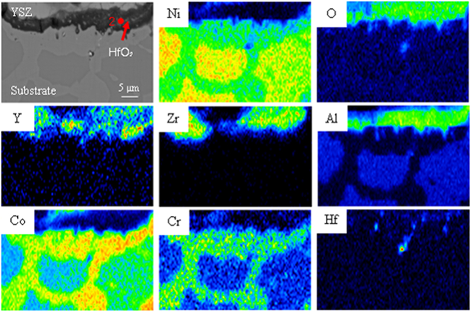
To examine the influence of water vapor on the oxidation performance, scanning electron microscopy (SEM) analysis was carried out on samples pre-oxidized for 24 h. After pretreatment for 24 h in air plus water atmosphere, it was found that small HfO2 particles were observed in the alumina layer (Fig. 5). The chemical composition of point 2 of the part in Fig. 5 is given in Table II. Propagation of holes and cracks is the result of stress development, and oxidation lifetime would increase. In this way, continuous oxidation in air would reduce the inhomogeneous stress distribution caused by HfO2, mitigate the growth of TBC internal stress, and reduce the growth rate of holes and cracks, which lead to the extension of oxidation lifetime. To observe the distribution of elements in detail and further analyze the effect of HfO2 distribution in the oxide layer. The corresponding element diagram is provided in Fig. 5. It is further proved that the presence of water atmosphere and the distribution of HfO2 can inhibit the formation of holes and cracks in the oxide layer and increase the service life of the coating.
EPMA analysis of element distribution after oxidation at 1050 °C in water vapor for 24 h.

Chemical composition of point 1 in the figures (at.% or ppma).

Oxidation resistance and failure mechanism of the coating
In this experiment, cyclic oxidation in different atmospheres resulted in different locations of HfO2 and the rate of hole and crack formation in the alumina layer. Because of different atmospheres, the internal stress was different in the TGO layer which can primarily affect the sample lifetime.
The effect of air and air containing water vapor on the oxidation process of NiCoCrAlYHf alloy was discussed. There is a gradient in the oxygen partial pressure from the YSZ/oxide interface to the oxidation/metal interface. According to Young et al. [Reference Young, Naumenko, Wessel, Singheiser and Quadakkers33], the oxygen flux across JO can be written as follows:
 $${D_{{\rm{eff}}}} = {{RT} \over {{\mu _{\rm{O}}}C}}{J_0}\partial x\quad ,$$
 $${\mu _{\rm{O}}} - \mu _{\rm{O}}^{\rm{0}} = RT\ln {\rm{p}}{{\rm{O}}_2}\quad ,$$
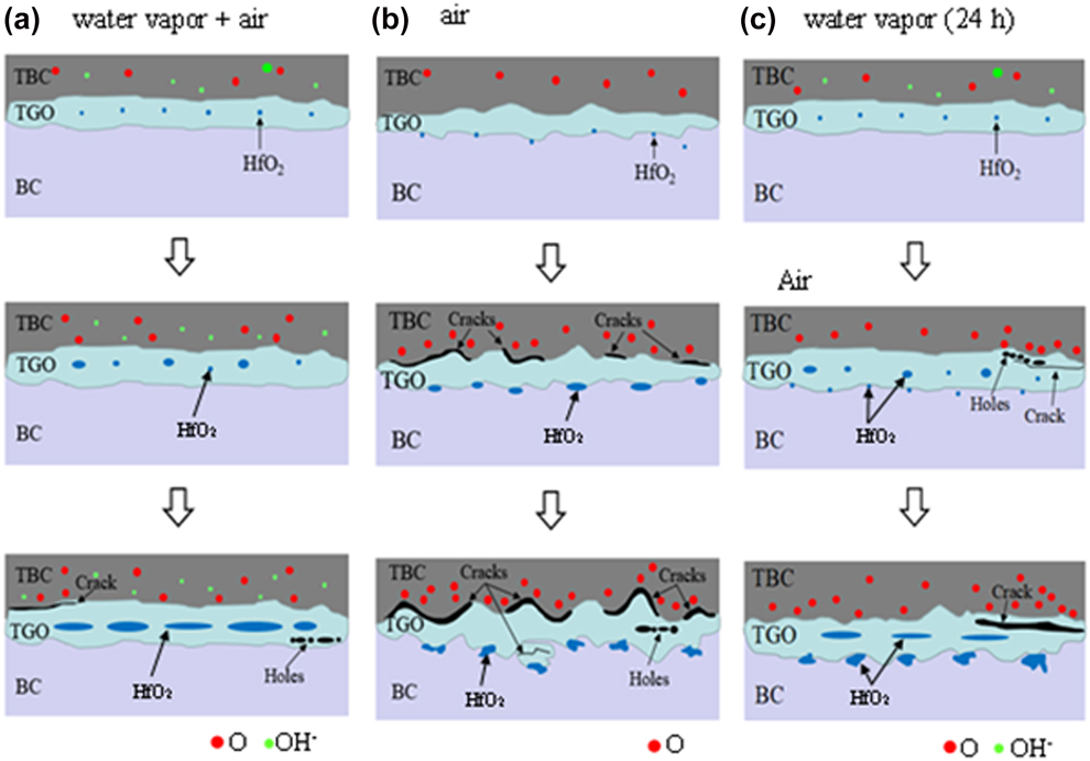
where μO is the oxygen chemical potential normally and does not change,  $\mu _{\rm{O}}^0$ is the chemical potential of pure oxygen, C is the concentration of the diffusing species, R is the gas constant, T is the oxidation temperature in Kelvin, x is the distance from the scale/gas interface, and pO2 is the oxygen partial pressure. Wang et al. [Reference Wang, Peng, Tan and Wang35] suggested that RE in aluminum-forming metals formed at the equilibrium partial oxygen pressure at the alumina/metal interface or below equilibrium oxygen pressure can be oxidized internally to form RExOy, and granular HfO2 can be produced in TGO. Oxygen concentration decreases with increasing depth. The HfO2 particles are generated by the oxidation of outwardly diffused Hf and inwardly diffused O. In air, less oxygen diffuses to the interface, so HfO2 particles can only grow at the interface. Water atmosphere promotes the internal diffusion of oxygen, so that more oxygen is diffused to the interface. Hf diffused externally can completely react with O, and Al and O continue to react to form alumina below the HfO2-rich layer, so that the HfO2 layer is formed in the TGO layer. In air containing water vapor, the oxygen partial pressure at the oxide/alloy interface is high, resulting in Hf segregation. Hf rapidly oxidizes at the interface and forms a layer mainly containing HfO2, which then accumulates gradually at the grain boundary of the alumina layer. However, HfO2 is not uniformly enriched at the oxide/alloy interface which is oxidized in air. HfO2 at the grain boundary produces grain boundary segregation, but its holes and cracks form slowly due to its intermediate position in the aluminum oxide layer. HfO2 below the grain boundary results in nonuniform stress and rapid formation of holes and cracks. The formation process of HfO2 for NiCoCrAlYHf alloys is shown in Fig. 6.
Schematic diagram of the formation process of the transition layer in NiCoCrAlHf alloy and YSZ with time. (a) Air + water vapor, (b) air, and (c) 24 h, water vapor + air.

The growth of the oxide layer was simulated according to the oxidation failure process (Fig. 6). It clearly shows oxygen and OH- diffusing inward in air containing water vapor [Fig. 6(a)], but the Al and Hf cations in the alloy diffuse outward and form an oxide layer at the alloy/YSZ interface as well as a small number of HfO2 at the oxide/alloy interface. Because the diffusion rate of Hf at the oxide/alloy interface is lower than that of Al and oxygen is slowly diffused inward, the growth rate of HfO2 below alloy/TGO interface is lower than that of external oxidation of Hf. As the oxidation progresses, the dissociation pressure of Al2O3 [pO2 (Al2O3)] is higher than the partial pressure of HfO2 [pO2 (Hf/HfO2)]. The gradual growth of HfO2 particles is attributed to the solubility of Hf (NHf) at a certain concentration and the precipitation of HfO2 increase in the oxide/alloy interface [Reference Li, Song, Khan, Feng, Chen, Zang, Xiong, Lü and Lu36]. Meanwhile, the aluminum oxide layer thickens. An internal oxide can be formed in the oxide/alloy interface to move the intermittent HfO2 upward, and then HfO2 is enriched in the alumina layer to form a layered structure. Figure 6(b) shows a schematic of the formation process of TGO and HfO2 enrichment in air. Compared with the alumina of NiCoCrAlYHf alloy in the atmosphere, the oxygen concentration at the oxide/alloy interface is low, the nonuniform distribution of HfO2 formed by Hf at the oxide/alloy hinders the diffusion of oxygen, and the low partial pressure of oxygen also causes Al to diffuse outward and combine with oxygen to form Al2O3. As the oxidation proceeds, the alumina layer becomes thicker and HfO2 moves to the oxide/alloy interface. At the same time, the distribution of HfO2 is not uniform, resulting in a nonuniform distribution of internal stress and increased holes and cracks. After pre-oxidation in air containing water vapor [Fig. 6(c)], the HfO2-rich layer is first formed in the alumina layer [Fig. 6(a)]. As the oxidation in air continues, the HfO2 at the interface between the alumina and the matrix is gradually enriched and the distribution of HfO2 is not uniform, resulting in an increase in holes and cracks and an increase in stress. However, compared with air, the distribution process in TGO of HfO2 in air containing water vapor results in a slower rate of stress growth and a correspondingly longer oxidation life. Water vapor provides rapid diffusion of oxygen and accelerates phase transition. It can be regarded as a dopant [Reference Al-Abadleh and Grasslan34]. Therefore, the HfO2-rich layer in TGO is not found in air. It can be concluded that water vapor is one of the key factors for the formation position of HfO2 and the oxidation life of coatings.
Evans et al. [Reference Evans, He and Hutchinson37] determined the mechanism by which anions and cations control TGO growth and proposed the small strain assumption. For cation control, growth is governed by the outward diffusion of cations (such as Al, Hf, etc.). The stresses in BC and TBC remain unchanged, and the radial stress in the TGO is determined by (r < R):
 $$\sigma _{\theta \theta }^i - {\sigma _{\theta \theta }} = {{9E} \over {4\left( {1 - v} \right)}}\left( {1 - {r \over R}} \right)\quad ,$$
where E is the Young’s modulus, v is the Poisson’s ratio, and R is the radius of the imperfection. The growth of Al2O3 scale is controlled by cations, in which the growth of TGO occurs at the TGO/TBC interface, and BC is consumed at the internal TGO interface. The stress within TGO depends on the initial circumferential stress component,  $\sigma _{\theta \theta }^i$, and should
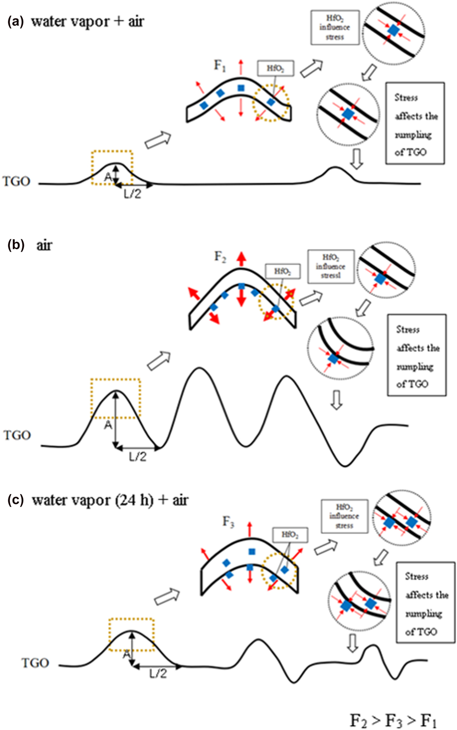
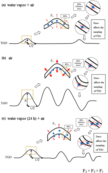
 $\sigma _{\theta \theta }^i \cong 0$, this stress will be compressive. The stress produced by the growth of TGO is definite, but in the growth of TGO stress, the initial circumferential stress is uncertain and can be prescribed arbitrarily. Applying a small hypothetical strain, there is no circumferential stress at the initial stage of oxidation. This force is 0, and the force controlled by cations is compressive stress. The stress caused by the position of HfO2 particles is shown in Fig. 7. HfO2 have led to a compressive stress in the Al2O3 layer, which partially offsets the stress caused by the fluctuation in the oxide layer, causing it to undulate more slowly. Part of HfO2 mainly distributed under the Al2O3 layer causes the low tensile stress to increase, which accelerates the fluctuation of the Al2O3 layer. This indicates that the HfO2 layer within TGO makes the distribution of internal stress uniform. The growth of internal stress evidently becomes slower. However, the HfO2 below accelerates the internal stress growth, which increases the holes and cracks of the alumina layer.
TGO stress distribution after cyclic oxidation in different atmospheres at 1050 °C. (a) Air + water vapor, (b) air, and (c) 24 h, water vapor + air.

There are two reasons for the failure of alumina produced by the coating: first, because the internal stress is high, it exceeds the mechanical fracture limit of Al2O3 itself, which leads to the shedding of Al2O3. Second, due to the development of holes and cracks in the alumina itself, its mechanical performance is degraded, and in the case of small internal stress, the holes and cracks may also cause the alumina to fall off and the coating to fail. The Al2O3 layer exhibited a large fluctuation and large strain after the oxidation cycle in air (Fig. 4), so that the distribution of internal stress is no longer uniform and local stress concentration easily forms in the nonuniform portion of the sample. According to the nonuniform distribution of the stress in the material, tensile stress forms easily at the upper edge of the alumina in the convex portion and pressure forms at the lower edge. After the oxidation in air, the greater number of holes and cracks led to a large oxygen partial pressure gradient. The internal stress concentration is nonuniform, so the oxidation lifetime is low in air containing water vapor. Once the above stress exceeds the mechanical fracture limit of alumina itself, cracks form and the coating falls off.
Holes and cracks will affect the coefficient of thermal expansion, and it can also reduce stress redistribution. Normal tension exists in the area where TGO is concave, and vice versa. Stress exists in oblique section. The ratio between elastic mismatch and amplitude A and wavelength L determines these stresses. The stresses are given by [Reference Evans, He and Hutchinson37]:
 $${H_{ij}} = {{{\sigma _{ij}}} \over {{\sigma _0}{\alpha _{\rm{D}}}}}{L \over A}\quad ,$$
where the misfit stress is:
 $${\sigma _0} = {{{E_0}} \over {\left( {1 - v} \right)}}\Delta {\alpha _0}\Delta T\quad ,$$
and αD is the Dundurs’ parameter, defined as:
 $${\alpha _{\rm{D}}} = {{{{\bar{E}}_1} - {{\bar{E}}_2}} \over {{{\bar{E}}_1} + {{\bar{E}}_2}}}\quad ,$$
where A and L are defined in Fig. 7, and  $\bar{E}$ is the plane strain Young’s modulus. Subscript 1 and 2 represent two adjacent materials. As the TGO fluctuations become larger, A and L have additional impact.
In Jesse P. Angle et al. [Reference Angle, Morgan, Mecartney and Cawley38], it was found that the solubility of oxides (NO) obtained by oxygen in water vapor was much higher than that of oxides (NO) obtained in air at the same diffusion depth, because (OH)-ions were smaller than O2-ions, easy to polarize, and conducive to faster diffusion. Wiederhorn and Bolz [Reference Wiederhorn and Bolz39] proposed that the stress corrosion of matrix is usually caused and controlled by chemical reaction between matrix and water. Meanwhile, Athanasiou [Reference Athanasiou40] found that the presence and content of water vapor had an effect on the mechanical properties of glass. RE affect the diffusion of oxygen through strong RE–O bonds [Reference Preis and Sitte19, Reference Hussain, Qureshi, Shahid, Chughtai and Khalid20] such that the charge compensation reaction of charged vacancies produced by Al/O affects the diffusion of Al on the grain boundaries of Al2O3. RE are mainly separated at grain boundaries of Al2O3, where diffusion usually occurs in practical systems [Reference Hou8, Reference Hussain, Qureshi, Shahid, Chughtai and Khalid20]. Water atmosphere can promote the diffusion of oxygen at grain boundaries of Al2O3 and greatly promote the formation of new oxides at the oxide/alloy interface. The results show that the distribution position of HfO2 is different in different oxidizing atmospheres, which leads to a longer oxidation life of NiCoCrAlYHf in water atmosphere than in air. Meanwhile, the oxidation resistance of NiCoCrAlYHf in air can be improved by pre-oxidation in water vapor atmosphere.
Conclusions
The effect of HfO2 position on the oxidation lifetime and the formation of TGO defects in the YSZ coatings deposited on NiCoCrAlYHf alloys in different atmospheres at 1050 °C was investigated. The following conclusions can be drawn:
(1) The lifetime of the TBC in air containing water vapor was significantly longer than that in air atmosphere. Pre-oxidation treatment in water vapor led to the formation of HfO2 in TGO, and the process will increase the lifetime of TBC obviously. The results showed that water was one of the key factors to improving the oxidation resistance of NiCoCrAlYHf alloys.
(2) In different atmospheres, the location of HfO2 was different. In air containing water vapor, HfO2 formed in the alumina layer, but in air HfO2 formed at the oxide/alloy interface. Meanwhile, the number of holes and cracks in TGO was related to the location of HfO2.
(3) HfO2-rich layer at the interface of TGO/alloy caused the internal stress concentration, large fluctuation of TGO, and reduced the TBC lifetime. However, the distribution of HfO2 in TGO resulted in a slower internal stress, and the alumina layer showed smaller fluctuation and a longer oxidation lifetime.
Experimental procedure
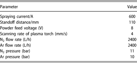
In this study, NiCoCrAlYHf (47.25Ni, 22.4Co, 17Cr, 12.5Al, 0.6Y, 0.25Hf, wt%) alloy specimens of 12 × 10 × 2 mm were made by vacuum casting and wire electrode cutting. Before the deposition process, the rectangular specimens were ground with sandpaper (1000# SiC) and then cleaned with an ultrasonic cleaner in ethanol or acetone. The surface of the specimens was sandblasted to remove the surface oxide scale and to obtain the same roughness. YSZ was sprayed on the sample surface according to the air plasma spraying parameters in Table III. The size and weight of the samples were measured.
Spraying parameters of NiCoCrAlYHf for atmospheric plasma spraying.

The experimental device shown in Fig. 1(a) made an experimental environment for air and air containing water vapor. The valves closed in air and opened in air containing water vapor. The part 2 of Fig. 1(a) was kept at 60 °C. Air and deionized water entered the furnace when the valves were opened, which caused a steam content of 25%.
The samples were exposed to the above two atmospheres by the device for oxidation until failure at 1050 °C. The oxidation cycle was set at 24 h, and the simples were removed from the furnace and weighed after cooling to room temperature (the time of cyclic oxidation did not include cooling time). When the YSZ separated from the NiCoCrAlYHf alloy surface, the samples failed.
The microstructure of the cross section was scanned stepwise using scanning electron microscopy (SEM) (Hitachi S-3500N, Hitachi, Tokyo, Japan), which was equipped with energy dispersive spectroscopy (EDS) (Oxford, Inca, England) equipment. The characteristics of the cross section were described by electron probe microanalysis (EPMA, JEOL JXA-8230, Akishima, Japan).
Acknowledgments
The authors acknowledge funding from the National Natural Science Foundation of China (Grant No. 51401097), Yunnan Province Science and Technology Major Project (Grant No. 2018ZE009), and Yunnan Province Key Research and Development Program (Grant No. 2018BA067).