I. INTRODUCTION
For polymer-based dielectric composites, both high permittivity and low dielectric loss are desired for practical applications.Reference Zhou, Zha, Hou, Wang, Zhao and Dang1 The conductor/polymer composites have attracted intensive interests in the last few years because of the potential applications in many electrical devices with advantages of high permittivity, lightweight, and easy processing.Reference Bowen, Newnham and Randall2–Reference Liu, Shen, Song, Nan, Lin and Yang9 However, the composites possess an insulator–conductor transition as the concentration of the conducting fillers approaches to the percolation threshold, which is called the percolation effect.Reference Dang, Yuan, Zha, Zhou, Li and Hu10–Reference Wang12 The conductive fillers in conductor/polymer composites not only increase the permittivity obviously but also inevitably induce plenty of free charge carriers and cause the dramatic increase in the leakage current and dielectric loss, which limits their applications in many fields.Reference Xie, Huang, Wu and Jiang13
To avoid dramatic increase of dielectric loss when adding more conductive fillers in conductor/polymer composites, insulator/semiconductor barrier layers coated around the conductor fillers are introduced, which prevent conducting fillers from connecting with each other and forming continuous conducting paths.Reference Shen, Lin, Li and Nan14–Reference Xu and Wong16 Composites with metal–insulator core–shell structure fillers show high permittivity and low dielectric loss. In which, the metal cores increase the permittivity owing to the interfacial polarizations, and the insulator shells are used to control the dielectric loss effectively, acting as barrier layers through blocking the electron transfer between the adjacent metal cores.Reference He, Lau, Chan and Fan17
So the composites filled with different core–shell structure fillers (Co@ZnO,Reference Wei, Jin, Zhong and Liu18 Ag@TiO2,Reference Zhou, Wang, Zhang, Bai, Niu and Wang19 Al@Al2O3,Reference Xu and Wong16 Ag@C,Reference Shen, Lin, Li and Nan14 and Ag@SiO2Reference Dang, You, Zha, Song and Li20) have been prepared by different methods, and their dielectric properties are significantly improved. Among the reported works on the composites with core–shell structure fillers, only a few studies are focused on exploring the intrinsic effect of the core–shell structure on the dielectric properties. Recently, Deng et al. compared the dielectric properties of Zn/PVDF, Zn@ZnO/PVDF, and ZnO/PVDF composites. It was found that the Zn@ZnO core–shell structure fillers affected the interfacial polarizations and free charge carriers, which contributed to the relatively high permittivity and low dielectric loss of the composites.Reference Zhang, Wang, Deng and Bai21 By phase-field modeling and computer simulation methods, scholars studied the dielectric composites with core–shell structure fillers and found that the permittivity of the shell close to that of the matrix could enhance the permittivity of the composite.Reference Wang, Tan and Krahn22
In this paper, we prepared Ag@SiO2 nanoparticles and Ag@SiO2/epoxy composites. In Ag@SiO2/epoxy composites, the Ag@SiO2 core–shell structure fillers can induce duplex interfacial polarizations, and the SiO2 shell layer possesses similar permittivity as that of epoxy matrix. By comparing with the composites filled with mixed Ag and SiO2 particles (Ag + SiO2), it is found that the filler Ag@SiO2 not only significantly enhance the permittivity but also effectively maintain the dielectric loss of the composite at 0.009 when the permittivity reaches to the maximum, and this dielectric loss value is far below those reported in the previous literature. On the other hand, the Ag@SiO2 particles have rough surfaces that are useful for the interfacial polarizations and the compatibility between the fillers and the matrix.
II. EXPERIMENTAL SECTION
A. Materials
AgNO3 was chosen as the starting material for the colloidal silver. Ethylene glycol was used as a solvent and reducing agent. Polyvinylpyrrolidone (PVP K30, M w 40,000) was used as a protecting agent. The polymer matrix epoxy resin was a glue solution including solvent, dispersing agent, curing agent, and so on, provided by Shengyi Tech Co., Ltd. (Dongguan, China).
B. Preparation of silver dispersions
PVP-protected colloidal silver dispersions were synthesized as follows.Reference Graf, Vossen, Imhof and Blaaderen23 Twenty grams of PVP was dissolved in 75 mL ethylene glycol at room temperature, then 2 g AgNO3 was added to this solution. The suspension was then stirred at room temperature until complete dissolution of silver nitrate. Then, the solution was heated up to 120 °C and stirred for 1 h at this temperature. After that, the colloidal dispersion was cooled to room temperature with water, and a large amount of acetone was added to the colloidal dispersion, then the silver colloid was separated easily from the ethylene glycol by centrifugation and well redispersed in alcohol. The silver colloid was used for the preparation of Ag@SiO2 nanoparticles and characterized by TEM.
C. Preparation of Ag@SiO2, Ag, and SiO2 nanoparticles
The silver colloid was uniformly dispersed in 200-mL absolute ethanol, followed by the addition of 4-mL TEOS and a little ammonia, and stirred for 8 h. The obtained Ag@SiO2 suspension was then dried overnight and sintered at 600 °C for 4 h. In the end, the Ag@SiO2 nanoparticles were gotten and proved by TEM images.
For getting mixed powder (Ag + SiO2), the Ag and SiO2 nanoparticles were prepared separately according to similar processes to those used for Ag@SiO2 core–shell fillers and then mixed together.
D. Synthesis of the epoxy-based composites
A certain amount of sintered powder was added to epoxy glue solution and ball milled at 800 rpm for 4 h. The suspensions were then cast coated on PET to form films. The films were then heat-treated in a furnace at 180 °C for 2 h.
E. Characterization
The phase of the Ag@SiO2 nanoparticles was identified by x-ray diffraction (XRD) with Cu Kα radiation (Rigaku D/MAX-2400 diffractometer, Tokyo, Japan). The core–shell structure was proved by transmission electron microscopy (TEM, JEOL JEM-2100, Tokyo, Japan) images. The microstructures of the composites were observed by a scanning electron microscope (SEM, JEOL, JSM-6460, Tokyo, Japan). All samples were prepared by fracturing the composites at room temperature and then sputter-coated with a gold layer on the fracture surfaces. Dielectric measurement was carried out by an impedance analyzer (Agilent 4294A, Palo Alto, CA) in the frequency range from 1 kHz to 10 MHz and in a temperature range from RT to 150 °C.
III. RESULTS AND DISCUSSION
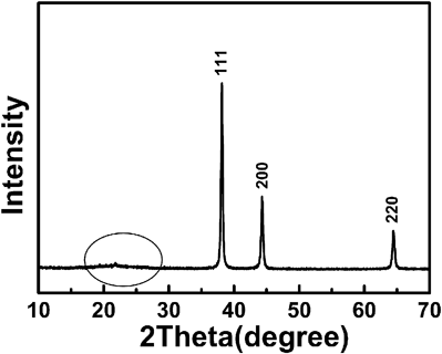
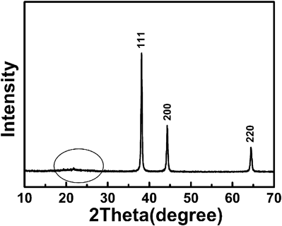
Figure 1 shows the scheme to form the Ag@SiO2 core–shell structure [Fig. 1(a)] and the comparison between the mixture powder (Ag + SiO2) and the core–shell structure particles Ag@SiO2 [Fig. 1(b)]. Figure 2 shows the XRD patterns of Ag@SiO2 nanoparticles, which reveal that the SiO2 shell is amorphous with a broaden diffraction peak appearing at about 21.5°. The diffraction peaks with 2θ values at 38.1, 44.3, and 64.4 correspond to the (111), (200), and (220) crystal planes of Ag, respectively. No Ag2O diffraction peak is observed even though the Ag@SiO2 nanoparticles were sintered at 600 °C.
(a) The forming mechanism of the Ag@SiO2 core–shell structure and (b) the schematic diagram of the mixed powders of (Ag + SiO2) and the core–shell structure particles of Ag@SiO2.

XRD patterns of Ag@SiO2 nanoparticles after being sintered at 600 °C.
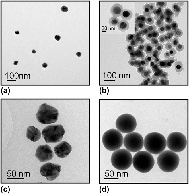
As shown in Fig. 3(a), the silver colloids have a regular and polyhedral particle shape and a narrow size distribution between 30–60 nm. Figure 3(b) exhibits the approximately spherical Ag@SiO2 core–shell particles with diameters of about 60–80 nm, without obvious aggregation and multiple silver cores. The inset image shows that the Ag cores are homogeneously coated with amorphous SiO2 layers, respectively, and the SiO2 shell layers make the surfaces of the core–shell structure particles roughly. Furthermore, the Ag cores become exactly spheres, different from the previously uncoated Ag particle shapes [Fig. 3(a)]. Figures 3(c) and 3(d) show the Ag and SiO2 particles that are used to form the mixed powders (Ag + SiO2). As seen in Fig. 3(d), the surface of the SiO2 spheres is smoother than that of the SiO2 shell layers in the Ag@SiO2 core–shell particles.
(a) TEM images of silver colloids and (b) Ag@SiO2 core–shell particles; (c) and (d) are Ag and SiO2 nanoparticles to form the mixture powder (Ag + SiO2).
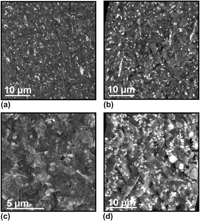
The SEM cross-section images [Figs. 4(a) and 4(b)] of the Ag@SiO2/epoxy composites with 50% and 60% mass fractions show homogeneous filler dispersion in the epoxy matrix. From the enlargement of the composite with 60% mass fraction [Fig. 4(c)], it is found that all the nanoparticles are embedded in the epoxy matrix, and there is no evident particle-matrix debonding, which indicates very strong interfacial bonding and excellent compatibility between the filler and the matrix. As seen in Fig. 4(d), the fracture surface of the composite is filled with 60% (Ag + SiO2) powders; this shows that the Ag and SiO2 particles tend to form agglomerates. In Ag@SiO2/epoxy composites, the Ag particles are coated by the insulating SiO2 shell layers and form homogeneous and rough surfaces to contact with the epoxy matrix. The surfaces of the fillers become rough, and the interfacial area between the filler and the matrix is increased, which is useful to improve the compatibility between the Ag@SiO2 nanoparticles and the epoxy as well as to enhance the interfacial polarizations and dielectric properties of the composites.
SEM images of fractured cross-surface of the epoxy-based composites with different mass fractions: (a) 50% Ag@SiO2, (b) 60% Ag@SiO2, (c) enlargement of 60% Ag@SiO2, and (d) 60% (Ag + SiO2).
Figure 5 shows the dielectric properties of (Ag + SiO2)/epoxy and Ag@SiO2/epoxy composites at 60% mass fraction. The permittivity of Ag@SiO2/epoxy composites is slightly higher than that of (Ag + SiO2)/epoxy composites, which can be ascribed to the duplex interfacial polarizations induced by Ag–SiO2 interface and SiO2–epoxy interface.Reference Graf, Vossen, Imhof and Blaaderen23 The dielectric loss value of the Ag@SiO2/epoxy composite is as low as 0.009 at 1 kHz and in a broad frequency range which is lower than that of the composite (Ag + SiO2)/epoxy. The result indicates that the Ag@SiO2 core–shell structure fillers can keep the dielectric loss of the composites at a low level value, which shows that the polarizations are relatively weakened step-by-step from the core to the matrix. In (Ag + SiO2)/epoxy composite, the interfacial polarization between the filler and the matrix is effective to enhance the permittivity of the composite. On the other hand, the increasing incompatible interfaces, such as SiO2–epoxy, Ag–epoxy, and so on, lead to more defects and air holes in the composite [Fig. 4(d)], which will decrease the permittivity of the composite. Under the influence of the two factors, the permittivity reaches to a balanced value; however, the dielectric loss is increased obviously due to the accumulating electric charges at the interfaces.Reference Shen, Lin and Nan24
Comparison of dielectric properties of Ag@SiO2/epoxy and (Ag + SiO2)/epoxy composites with the same mass fraction filling at 60%.
The frequency dependencies of dielectric properties of the composites with different contents of Ag@SiO2 particles are shown in Figs. 6(a) and 6(b). The permittivity of the composites is nearly independent of the frequency [Fig. 6(a)], and the dielectric loss apparently increases as the frequency increases from 1 to 100 kHz and then is almost unchanged [Fig. 6(b)]. Figure 6(c) shows the dielectric properties of (Ag + SiO2)/epoxy and (Ag@SiO2)/epoxy composites at 1 kHz with different contents. For these two kinds of composites, the permittivity increases moderately when the filler percentages are below 50% and increases significantly as the filler contents are more than 50%. The maximum values of the permittivity are reached when the filler content is 60%, and further addition of (Ag + SiO2) and Ag@SiO2 nanoparticles into epoxy leads to a decrease in the permittivity following a jump in the dielectric loss of the composites, which is mainly due to the formation of voids and interfacial defects, induced by aggregation between excess filler particles.Reference Chon, Ye, Cha, Lee, Koo, Jung and Kwon25 As shown in Fig. 5, the permittivity of (Ag@SiO2)/epoxy composites is higher than that of the (Ag + SiO2)/epoxy, which is due to the interfacial polarizations in core–shell structure fillers, just like many microcapacitors dispersing into the epoxy host. In Fig. 6(c), there is another interesting phenomenon that should be noted, the permittivity increases as the filler content of the Ag@SiO2/epoxy composites increases, before 60% mass fraction, and the dielectric loss decreases and even reaches the lowest value at the content of 60%. However, the dielectric loss of (Ag + SiO2)/epoxy composites gradually increases as the filler content increases. The different variation tendency in dielectric loss is ascribed to the SiO2 shell layer coated outside of the Ag nanoparticles in Ag@SiO2/epoxy. When the dielectric loss decreases from 0.019 [for (Ag + SiO2)/epoxy at 60% concentration] to 0.009 [for (Ag@SiO2)/epoxy at 60% concentration], the reduction is approximately 53%. At the same time, the permittivity is as high as 11.3 at 1 kHz, which is about 1.5 times higher than that of the pure epoxy. So the optimized Ag@SiO2/epoxy composite is a good candidate for the applications of embedded passive components and other related electronic devices.
The frequency dependencies of (a) permittivity and (b) dielectric loss of the Ag@SiO2/epoxy composites with various Ag@SiO2 mass fractions; (c) is the dielectric properties of (Ag@SiO2)/epoxy and (Ag+SiO2)/epoxy composites at 1 kHz versus different filler contents.
Figure 7 shows the temperature dependencies of the dielectric properties of Ag@SiO2/epoxy composites with 30% and 60% mass fractions, measured at the frequencies of 1 kHz and 1 MHz, in the temperature range from 45 to 150 °C. The permittivity gradually increases as the temperature increases, which is mainly because the segment mobility of the polymer molecules is increased as the temperature rises. Of course, the remarkable dipole polarizations in the Ag@SiO2 core–shell structure and epoxy also make significant contributions to the increase of the permittivity.Reference Dang, Zhou, Yao, Yuan, Zha, Song, Li, Chen, Yang and Bai26,Reference Psarras, Manolakaki and Tsangaris27 On the other hand, the permittivity and dielectric loss attain high values in 1 kHz and decrease as frequency increases to 1 MHz. This behavior indicates a relaxation process and is attributed to an interfacial polarization, known as the Maxwell–Wagner–Sillars (MWS) effect,Reference Lunkenheimer, Bobnar, Pronin, Ritus, Volkov and Loidl28,Reference Li, Seok, Chu, Dogan, Zhang and Wang29 which will appear when the charges accumulate at the interfaces in heterogeneous media.
The temperature dependencies of the dielectric properties of Ag@SiO2/epoxy composites with 30% and 60% mass fractions and measured at the frequencies of 1 kHz and 1 MHz and in the temperature range from 45 to 150 °C.
IV. CONCLUSIONS
In conclusion, the Ag@SiO2 metal–insulator core–shell structure fillers are effective to improve the dielectric properties of Ag@SiO2/epoxy composites, by introducing the duplex interfacial polarizations and a small amount of free charge carriers. Especially, the insulating shell layers of SiO2, which changes the interface interaction between Ag and epoxy matrix, not only avoid Ag particles to connect directly and aggregate together but also provide rough surfaces which are useful to enhance the compatibility between the Ag@SiO2 fillers and the epoxy matrix.
ACKNOWLEDGMENTS
This work was supported by National Science Foundation of China (61025002) and National 973-project of China (2009CB623302).